OR manual CORON - tantum AG
OR manual CORON - tantum AG
OR manual CORON - tantum AG

You also want an ePaper? Increase the reach of your titles
YUMPU automatically turns print PDFs into web optimized ePapers that Google loves.
<strong>OR</strong> <strong>manual</strong><br />
C<strong>OR</strong>ON
<strong>tantum</strong> · <strong>OR</strong> <strong>manual</strong> C<strong>OR</strong>ON<br />
2<br />
Duo-head Acetabular cup<br />
Head Large head<br />
Flexibility - thanks to<br />
the modular set up:<br />
the best treatment for<br />
each indiation can be<br />
achieved through<br />
various components.
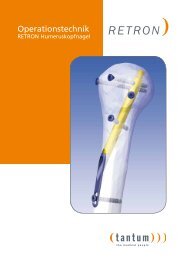
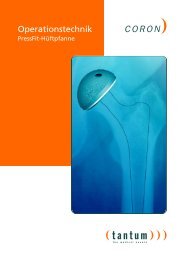
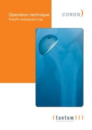
C<strong>OR</strong>ON – The cemented<br />
hip endoprosthesis by <strong>tantum</strong><br />
<strong>tantum</strong> · <strong>OR</strong> <strong>manual</strong> C<strong>OR</strong>ON<br />
The <strong>tantum</strong> Straight Stem-Hip-Endoprosthesis-System<br />
Years of experience and excellent clinical results with<br />
the implantation of cemented straight stem prosthesis<br />
led to the development of the <strong>tantum</strong> Straight Stem-<br />
Hip-Endoprosthesis-System. The system with its modular<br />
concept, allows individual adjustment with the<br />
treatment of medial femoral neck fractures in elderly<br />
patients.<br />
System components:<br />
– Straight Stem-Hip-Endoprosthesis, cemented, with<br />
matt surface, 12/14mm Conus<br />
– Head of steel, 28 mm diameter, three neck-lenghts<br />
– Acetabular cup: of PE, cemented<br />
– Duo-head: external shell of steel with inlay of PE,<br />
28mm diameter.<br />
– Large head: of steel, one neck length<br />
Our prothesis´ stems are manufactured from high<br />
nitrogen alloy implant steel following ISO 5832-9.<br />
Indication<br />
Medial femoral neck fractures, with or without coxarthrosis<br />
in elderly patients<br />
Recommendation of treatment<br />
– Patients with coxarthrosis: total replacement of the<br />
hip joint with cemented acetabular cup and stem<br />
– Patients without coxarthrosis: duo-head with cemented<br />
stem<br />
– Bedridden patients: large head with cemented stem<br />
3
<strong>tantum</strong> · <strong>OR</strong> <strong>manual</strong> C<strong>OR</strong>ON<br />
Implantation of the C<strong>OR</strong>ON-<br />
Hip-Endoprosthesis with<br />
Duo-Head or Large Head<br />
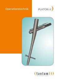
Fig. 1<br />
Fig. 2<br />
4<br />
10-15°<br />
1. Positioning and opening<br />
The patient must be positioned supine with the affected<br />
side slightly elevated. The approach is made by<br />
administering a curved skin incision with the greater<br />
trochanter at the center. This incision is then directed<br />
towards the anterior superior iliac spine. Exposure of<br />
the gluteus medius muscle and splitting in line with the<br />
muscle fibers (Fig. 1).<br />
Positioning of two Hohmann retractors ventrally and<br />
dorsally of the femoral neck. Opening of the capsule<br />
and resection of the ventral parts. Now the fracture<br />
can be exposed.<br />
2. Resection of the femoral neck<br />
Change of the Hohmann retractors position by placing<br />
them intraarticular. Depending on the type of fracture,<br />
the femoral head can now be fixated and dislocated.<br />
Measuring the head diameter with the gauge.<br />
Osteotomy of the femoral neck in a line 1cm ventrally<br />
of the lesser trochanter reaching in a 45° angle<br />
towards the greater trochanter. Next, the femoral<br />
head is removed (Fig. 2).
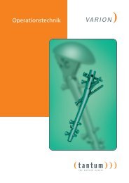
Fig. 3<br />
Fig. 4<br />
3. Preparation of the femoral shaft<br />
<strong>tantum</strong> · <strong>OR</strong> <strong>manual</strong> C<strong>OR</strong>ON<br />
Adduction and external rotation of the femur.<br />
Opening of the medullary cavity, with a sharp spoon,<br />
directly at the medial femoral cortex and removal of<br />
the bone marrow as far as the femoral canal. Manual<br />
reaming of the medullary cavitiy by using the reamers<br />
(Pos. 13) (Fig. 3), beginning with the smallest size until<br />
the cranial end of the reamer can be completely inserted<br />
into the intramedullary canal aligning the femoral<br />
neck resection.<br />
Inserting the prosthesis and eventually verification of<br />
the exact position with the image intensifier. Removal<br />
of the trial prosthesis.<br />
4. Implantation of the straight-stem-prosthesis<br />
Insert the medullary canal plug (PE) (cement stopper,<br />
Pos. 18) with the handle for the cement stopper (Pos.<br />
5) into the distal medullary canal. Instead of the PEplug,<br />
cancellous bone from the femoral head can be<br />
used as an alternative. Preparation of the bone cement<br />
in vacuum technique and placing an air escape tube in<br />
the medullary canal.<br />
Injection of the cement and insertion of the definite<br />
prosthesis to the appropriate marking (Fig. 4). While<br />
hardening, the cement must be pressurized with slight<br />
pressure of the impactor (Pos. 8) on the prosthesis.<br />
After irrigating the joint with large amounts of<br />
Ringer´s solution, the capsule resection borders must<br />
be finally checked for bleeding.<br />
5
<strong>tantum</strong> · <strong>OR</strong> <strong>manual</strong> C<strong>OR</strong>ON<br />
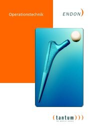
Fig. 5<br />
Fig. 6<br />
6<br />
40°<br />
5. Implantation of the Duo-Head or the Large Head<br />
Placing the trial head (Pos. 2 and 16) (Duo-Head: middle<br />
neck length of the trial head (Pos. 15)) in the previous<br />
chosen size into the hip-joint (Fig. 5). If the measured<br />
size lies between two sizes, the smaller one must<br />
be chosen.<br />
Trial reduction and verification of the leg length, the<br />
range of motion and an eventual tendency for luxation.<br />
With implantation of a Duo-Head, correction by<br />
changing to a head with a different neck length might<br />
be necessary, eventually, by using the wedge (Pos. 12)<br />
for femoral heads.<br />
Removal of the trial head and positioning of the definite<br />
implant (Fig. 6) (Duo-Head: after placing the desired<br />
femoral head into the Duo-Head with the Duo-<br />
Head-forceps, Pos. 1). Placement of two Redon-drains<br />
dorsally and laterally. Finally, closure of the wound one<br />
layer at a time.
Implantation of the C<strong>OR</strong>ON-<br />
Hip-Endoprosthesis with<br />
cemented acetabular cup<br />
Fig. 7<br />
Fig. 8<br />
10-15°<br />
1. Positioning and opening<br />
The patient must be positioned supine with the affected<br />
side slightly elevated. The approach is made by<br />
administering a curved skin incision with the greater<br />
trochanter at the center. This incision is then directed<br />
towards the anterior superior iliac spine. Exposure of<br />
the gluteus medius muscle and splitting in line with the<br />
muscle fibers (Fig. 7).<br />
Positioning of two Hohmann retractors ventrally and<br />
dorsally of the femoral neck. Opening of the capsule<br />
and resection of the ventral parts. Now the fracture<br />
can be exposed.<br />
2. Resection of the femoral neck<br />
<strong>tantum</strong> · <strong>OR</strong> <strong>manual</strong> C<strong>OR</strong>ON<br />
Change of the Hohmann retractors position by placing<br />
them intraarticular. Depending on the type of fracture,<br />
the femoral head can now be fixated and dislocated.<br />
Measuring the head diameter with the gauge.<br />
Osteotomy of the femoral neck in a line 1cm ventrally<br />
of the lesser trochanter reaching in a 45° angle<br />
towards the greater trochanter. Next, the femoral<br />
head is removed (Fig. 8).<br />
7
<strong>tantum</strong> · <strong>OR</strong> <strong>manual</strong> C<strong>OR</strong>ON<br />
Fig. 9<br />
Fig. 10<br />
Fig. 11<br />
8<br />
40°<br />
3. Preparation of the acetabulum<br />
Removal of the capsule in the cranial and caudal part.<br />
In order to minimize the danger of bleeding, it is<br />
recommended to leave the posterior part in place.<br />
Exposure of the acetabulum with a shaped Hohmannretractor,<br />
its tip placed behind the dorsal rim, and a<br />
second retractor positioned on the anterior rim. Then,<br />
resection of existing exophytes and cartilage of the<br />
acetabulum with the reamer (Pos. 4 und 14) in the previously<br />
selected size.<br />
4. Implantation of the acetabular cup<br />
Placement of the acetabular trial cup (Pos. 3 und 17) in<br />
the previously selected size and determination of the<br />
definite size (Fig. 9). For optimal fixation of the acetabular<br />
cup, drilling of two to three anchoring pivots for<br />
the bone cement cranially and medially. Irrigation of<br />
the joint with Ringer´s solution.<br />
Preparation of the bone cement and placement in the<br />
acetabulum. Implantation of the PE-acetabular cup,<br />
correctly angled, with the bent cup impactor (Pos. 6<br />
and 7) and hardening in the exact same postion (Fig.<br />
11). Excess cement must be cleaned off thoroughly<br />
before the final hardening.<br />
Finally, place armed, wet gauze into the cavity of the<br />
acetabular cup.
Fig. 12<br />
Fig. 13<br />
Fig. 14<br />
5. Preparation of the femoral shaft<br />
Adduction and external rotation of the femur.<br />
Opening of the medullary cavity, with a sharp spoon,<br />
directly at the medial femoral cortex and removal of<br />
the bone marrow as far as the femoral canal.<br />
Automatic and <strong>manual</strong> reaming of the medullary cavitiy<br />
by using the reamers (Pos. 13) (Fig. 12), beginning<br />
with the smallest size until the cranial end of the reamer<br />
can be completely inserted into the intramedullary<br />
canal aligning the femoral neck resection.<br />
Inserting the prosthesis and verification of the exact<br />
position with the image intensifier.<br />
6. Implantation of the straight-stem-prosthesis<br />
Insert the medullary canal plug (PE) (cement stopper,<br />
Pos. 18) with the handle for the cement stopper (Pos.<br />
5) into the distal medullary canal. Instead of the PEplug,<br />
cancellous bone from the femoral head can be<br />
used as an alternative. Preparation of the bone cement<br />
in vacuum technique and placing an air escape tube in<br />
the medullary canal. Injection of the cement and insertion<br />
of the definite prosthesis to the appropriate<br />
marking (Fig. 13). While hardening, the cement must<br />
be pressurized with slight pressure of the impactor<br />
(Pos. 8) on the prosthesis. After irrigating the joint with<br />
large amounts of Ringer´s solution, the capsule resections<br />
must be finally checked for bleeding.<br />
7. Implantation of the femoral head<br />
<strong>tantum</strong> · Operationstechnik C<strong>OR</strong>ON<br />
Placing the trial head of middle neck length (Pos. 15)<br />
onto the straight-stem-prosthesis. Reduction of the<br />
prosthesis into the PE acetabular cup and verification<br />
of exact leg length and eventual tendency for luxation.<br />
Eventual correction by changing to a head with a different<br />
neck length (Pos. 15).<br />
Removal of the trial head and positioning of the definite<br />
implant (Fig. 14) using the femoral head impactor<br />
(Pos. 9 und 10). After a last control of function, placement<br />
of two Redon-drains dorsally and laterally.<br />
Finally, closure of the wound one layer at a time..<br />
9
<strong>tantum</strong> · <strong>OR</strong> <strong>manual</strong> C<strong>OR</strong>ON<br />
01) 200-100 Duo-head forceps<br />
02) 200-120 Handle for trial heads<br />
03) 200-121 Handle for size tester<br />
04) 200-122 Handle for cup reamer<br />
05) 200-123 Handle for cement stopper<br />
06) 200-124 Cup inserter, bended<br />
07) 200-125 Head for cup inserter<br />
08) 200-126 T-handle<br />
09) 205-130 Hammer for straight stem<br />
10) 205-131 Impactor for head<br />
11) 205-132 Cap for head impactor<br />
10<br />
C<strong>OR</strong>ON Instruments<br />
12) 205-134 Wedge for head<br />
13) Straight stem mono reamer<br />
7.5 207-101 11.25 207-104<br />
8.75 207-102 12.5 207-105<br />
10.0 207-103 13.75 207-106<br />
2002<br />
December<br />
14) Cup reamer<br />
notice.<br />
Ø 44 mm 207-111 Ø 54 mm 207-116 prior<br />
Ø 46 mm 207-112 Ø 56 mm 207-117<br />
Ø 48 mm 207-113 Ø 58 mm 207-118<br />
Ø 50 mm 207-114 Ø 60 mm 207-119 without<br />
Ø 52 mm 207-115 Ø 62 mm 207-120<br />
occur may<br />
15) Trial head<br />
changes<br />
S, Ø 28 mm, 12/14 208-120<br />
M, Ø 28 mm, 12/14 208-121<br />
L, Ø 28 mm, 12/14 208-122<br />
16)<br />
measurements.Technical<br />
Trial head<br />
Ø 42 mm 208-152 Ø 50 mm 208-126<br />
Ø 44 mm 208-123 Ø 52 mm 208-127 original<br />
Ø 46 mm 208-124 Ø 54 mm 208-128<br />
the<br />
Ø 48 mm 208-125 Ø 56 mm 208-129to<br />
equivalent not<br />
17) Size tester<br />
and<br />
Ø 44 mm 208-133 Ø 54 mm 208-138<br />
Ø 46 mm 208-134 Ø 56 mm 208-139<br />
Ø 48 mm 208-135 Ø 58 mm 208-140schematic<br />
Ø 50 mm 208-136 Ø 60 mm 208-141<br />
Ø 52 mm 208-137 Ø 62 mm 208-142<br />
are shown figures<br />
18) 102-103 Cement stopper The
C<strong>OR</strong>ON Components<br />
Head, sterile<br />
Material: steel (ISO 5832-9)<br />
Diameter: 28 mm<br />
Cone: 12/14 mm<br />
Neck length Art. No.<br />
S 102-100<br />
M 102-101<br />
L 102-102<br />
Duo-head, sterile<br />
Material:<br />
External shell:<br />
steel (ISO 5832-1)<br />
Inlay: PE (ISO 5834-2)<br />
Inlay Ø: 28 mm<br />
Outer Ø Art. No.<br />
42 mm 102-205<br />
44 mm 102-206<br />
46 mm 102-207<br />
48 mm 102-208<br />
Large head, sterile<br />
Material: steel (ISO 5832-1)<br />
Cone: 12/14 mm<br />
Outer Ø Art. No.<br />
40 mm 102-110<br />
42 mm 102-111<br />
44 mm 102-112<br />
46 mm 102-113<br />
48 mm 102-114<br />
50 mm 102-115<br />
Outer Ø Art. No.<br />
50 mm 102-209<br />
52 mm 102-210<br />
54 mm 102-211<br />
56 mm 102-212<br />
Outer Ø Art. No.<br />
52 mm 102-116<br />
54 mm 102-117<br />
56 mm 102-118<br />
58 mm 102-119<br />
60 mm 102-120<br />
Straight stem, cemented, sterile<br />
Material: steel (ISO 5832-9)<br />
Cone: 12/14 mm<br />
Surface: matt<br />
Size Art. No.<br />
7.5 102-401<br />
8.75 102-402<br />
10.0 102-403<br />
11.25 102-404<br />
12.5 102-405<br />
13.75 102-406<br />
Acetabular cup, cemented, sterile<br />
Material: PE (ISO 5834-2)<br />
Inner Ø: 28 mm<br />
Outer Ø Art. No.<br />
44 mm 102-300<br />
46 mm 102-301<br />
48 mm 102-302<br />
50 mm 102-303<br />
52 mm 102-304<br />
Cement stopper, sterile<br />
Material: PE (ISO 5834-2)<br />
X-ray indicator: steel<br />
Art. No. 102-103<br />
Outer Ø Art. No.<br />
54 mm 102-305<br />
56 mm 102-306<br />
58 mm 102-307<br />
60 mm 102-308<br />
62 mm 102-309<br />
11
<strong>tantum</strong> <strong>AG</strong><br />
Mühlenhof 65<br />
D-24534 Neumünster<br />
Telephone +49 4321-2 00 59 0<br />
Fax +49 4321-2 00 59 19<br />
info@<strong>tantum</strong>-ag.de