CFD MODELLING OF AERODYNAMICS IN A SOLAR – ENHANCED ...
CFD MODELLING OF AERODYNAMICS IN A SOLAR – ENHANCED ...
CFD MODELLING OF AERODYNAMICS IN A SOLAR – ENHANCED ...

Create successful ePaper yourself
Turn your PDF publications into a flip-book with our unique Google optimized e-Paper software.
Ninth International Conference on <strong>CFD</strong> in the Minerals and Process Industries<br />
CSIRO, Melbourne, Australia<br />
10-12 December 2012<br />
<strong>CFD</strong> <strong>MODELL<strong>IN</strong>G</strong> <strong>OF</strong> <strong>AERODYNAMICS</strong> <strong>IN</strong> A <strong>SOLAR</strong> <strong>–</strong> <strong>ENHANCED</strong><br />
VORTEX GASIFIER (SVG): PART II. A PRELIM<strong>IN</strong>ARY STUDY <strong>OF</strong> THE<br />
LOCATIONS <strong>OF</strong> SEAL GAS <strong>IN</strong>LETS<br />
Jing YU, Yuchuan CAO, Zhaofeng TIAN*, Yunpeng XUE & Graham NATHAN<br />
School of Mechanical Engineering, The University of Adelaide, South Australia 5005, Australia<br />
ABSTRACT<br />
This paper reports a computational fluid dynamics<br />
(<strong>CFD</strong>) study of isothermal gas flows and particle<br />
trajectories in a Solar-enhanced Vortex Gasifier<br />
(SVG). The aim of this study is to develop a novel<br />
aerodynamic method to replace the critical quartz<br />
window in the current SVG design. A <strong>CFD</strong> model<br />
of the SVG has been developed based on the<br />
commercial <strong>CFD</strong> package ANSYS/CFX. Seal gas<br />
curtains injected from six different inlets, namely<br />
three different radial inlets, two different horizontal<br />
inlets and one tangential inlet at the aperture in the<br />
SVG, are simulated and compared using the <strong>CFD</strong><br />
model. From this preliminary analysis, it is found<br />
that the radial gas inlet located on the middle of the<br />
conical surface of the reactor has better performance<br />
in keeping particles inside the SVG than the other<br />
two radial inlets. However, it is insufficient to keep<br />
all particles in the SVG. The two horizontal inlets<br />
are not ideal for particle sealing purpose either. The<br />
case with six tangential inlets at the aperture is<br />
found to be the most promising configuration<br />
identified to date for retaining particles in the SVG.<br />
Concentra<br />
ted solar<br />
power<br />
Copyright © 2012 CSIRO Australia<br />
*Email Address: zhao.tian@adelaide.edu.au<br />
Aperture plane<br />
Quartz<br />
window<br />
Front cone<br />
Particle inlet<br />
1<br />
<strong>IN</strong>TRODUCTION<br />
Solar driven gasification is a new technology that<br />
uses solar energy to transform solid fuels into<br />
syngas, comprising H 2, CO and inerts (Piatkowski et<br />
al., 2011). Compared with conventional gasification<br />
systems, the products of solar enhanced gasification<br />
system are cleaner, with higher utilization ratio, and<br />
wider applications (Piatkowski et al., 2011).<br />
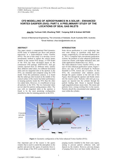
The Solar-enhanced Vortex Gasifier (SVG) is one<br />
type of solar enhanced gasification system. Figure 1<br />
shows one type of SVG developed by Professor<br />
Steinfeld at ETH, Zurich and co-workers. In this<br />
SVG, the concentrated solar radiation passes<br />
through the quartz window at the left end of the<br />
Figure, then through the aperture and finally enters<br />
into the reactor cavity. Particles with inert gas (e.g.<br />
argon) are injected into the cylinder through the<br />
particle feeding inlet. Steam is injected through<br />
eight tangential primary steam inlets. The steam and<br />
particles form a strong swirling flow in the reactor.<br />
Particles absorb the concentrated solar radiation and<br />
react within the cylinder.<br />
Figure 1: Geometric configuration of the Solar-enhanced Vortex Gasifier (SVG).<br />
One important part of the reactor is the quartz<br />
window that is used to control the atmosphere in the<br />
gasifier and prevent the egress of particles from it.<br />
Current design of the SVG system includes several<br />
Steam inlets<br />
Reactor cavity<br />
Outlet<br />
purging nozzles installed in the front cone region,<br />
aiming to prevent particle collisions with, and<br />
deposit on, the window. However, previous designs<br />
of purging flows have not been totally effective so
that particles still can deposit on the window. Due to<br />
the decreased transmissivity of the quartz window<br />
covered by the particles, reduction of the solar<br />
power absorption will lead to a drop of the reactor‘s<br />
efficiency. Furthermore, the deposited particles<br />
reach very high temperatures by absorbing the<br />
concentrated solar radiation, leading to a high<br />
probability of failure of the window. Therefore, an<br />
aerodynamic method is sought to replace the quartz<br />
window, i.e. using seal gas curtains to retain the<br />
particles within the reactor.<br />
A computational fluid dynamics (<strong>CFD</strong>) study of<br />
isothermal gas flow in the SVG is currently being<br />
undertaken in the School of Mechanical<br />
Engineering, University of Adelaide. The <strong>CFD</strong><br />
model is based on the SVG furnace of Z‘Graggen et<br />
al. (2006).<br />
There are no measurements of gas velocity fields in<br />
the SVG available in the literature for model<br />
development and validation. Therefore, a level of<br />
confidence of the modelling results has been<br />
established by validating the <strong>CFD</strong> model in an<br />
isothermal flow in another solar chemical reactor<br />
Copyright © 2012 CSIRO Australia<br />
2<br />
(Meier et al., 1996) developed by the same group.<br />
This solar chemical reactor has similar swirling flow<br />
patterns to those in the SVG and properties of<br />
isothermal flows in the reactor are available from<br />
the literature. In this validation case, it is found the<br />
Baseline Reynolds Stress (BSL) model, and<br />
Speziale, Sarkar and Gatski (SSG) Reynolds Stress<br />
model perform better than the Shear-Stress-<br />
Transport (SST) model. The SSG Reynolds Stress<br />
model is chosen, however, since it has better<br />
convergence. The validation results were reported in<br />
part I of this work (Cao et al., 2012), presented at<br />
the same conference.<br />
The aim of the present investigation is to use this<br />
validated <strong>CFD</strong> model to investigate effectiveness of<br />
various configurations of seal-gas inlet at preventing<br />
particle egress through an open aperture, with a<br />
view to eventually replacing the quartz window with<br />
seal-gas curtains. The current paper reports some<br />
preliminary results of influence of six<br />
configurations of seal-gas curtains on particle<br />
trajectories through the aperture of the SVG.<br />
Case number 1 2 3 4 5 6<br />
Curtain inlet<br />
configuration<br />
Seal gas<br />
velocities<br />
Particle inlet<br />
mass flow-rate<br />
Total No. of<br />
mesh nodes<br />
No. of<br />
Elements<br />
Radial inlet 1<br />
See Figure 2<br />
Radial inlet 2<br />
See Figure 2<br />
Radial inlet 3<br />
See Figure 2<br />
Axial inlet 1<br />
See Figure 3a<br />
1 m/s 1 m/s 1 m/s 2.5 m/s<br />
Axial inlet 2<br />
See Figure 3b<br />
2.5 m/s<br />
Tangential<br />
inlet<br />
See Figure 4<br />
2.5 m/s<br />
6e-4kg/s 6e-4kg/s 6e-4kg/s 6e-4kg/s 6e-4kg/s 6e-4kg/s<br />
497,333 491,088 492,586 492,948 494,773 492,556<br />
2,029,869 1,968,855 1,985,654 1,839,737 2,002,172 1,859,746<br />
Table 1: Details of the different cases investigated.<br />
Radial inlet 1<br />
Radial inlet 2<br />
Radial inlet 3<br />
Figure 2: Radial gas inlets of Case 1 (Radial inlet<br />
1), Case 2 (Radial inlet 2) and Case 3 (Radial inlet<br />
3).<br />
Figure 3: Axial inlets at the same location as for<br />
part (a), termed Case 4, (b) Case 5.
Figure 4: Six tangential inlets at the throat: Case 6.<br />
MODEL DESCRIPTION<br />
Figure 1 shows the geometry of the SVG device that<br />
was modelled with the commercial package<br />
ANSYS/Designmodeler 14.0. The dimensions are<br />
based on available data from the literature<br />
(Z‘Graggen, 2008). The length of the cavity of the<br />
reactor from the aperture plane to the outlet is 0.210<br />
m. The diameter of the reactor cavity is 0.12 m.<br />
The diameter of aperture is 0.05 m. Particles and<br />
Argon are injected through the particle inlet at 0.03<br />
m downstream from the aperture plane. Steam is<br />
injected into the reactor from eight tangential inlets.<br />
To find the best location(s) for the seal gas inlets,<br />
the <strong>CFD</strong> model is used to simulate the internal flows<br />
and particle trajectories for six cases, namely, three<br />
different radial gas curtain inlets (shown in Figure<br />
2), two six-axial-inlet cases (Figure 3) and one six-<br />
RESULTS AND DISCUSSIONS<br />
Figure 6 shows the particle trajectories when gas<br />
curtain inlet 1 is employed, i.e. the seal-gas is<br />
injected through the radial inlet at the aperture wall.<br />
It is apparent that some particles pass through the<br />
gas curtains and leave the SVG through the aperture.<br />
Copyright © 2012 CSIRO Australia<br />
Figure 5: The unstructured mesh of Case 2.<br />
3<br />
tangential-inlet case (Figure 4). In all reported cases,<br />
there is no quartz window and it is opening at the<br />
left hand end of the SVG. For the radial inlet cases,<br />
gas curtain inlets are all 2 mm in width. Radial gas<br />
curtain inlet 1 is located on the aperture plane<br />
(Figure 2). Radial gas curtain inlet 2 is located at the<br />
middle of the conical surface of the reactor and<br />
perpendicular to the surface. Radial gas curtain inlet<br />
3 is located at the cylinder surface next to the<br />
particle inlet. More details of these cases are given<br />
in Table 1.<br />
ANSYS/Meshing 14.0 was used to generate<br />
unstructured meshes. Mesh quality was checked in<br />
terms of skewness, aspect ratio, orthogonality, and<br />
expansion factor. The mesh numbers of all cases<br />
reported in the paper are given in Table 1. Figure 5<br />
shows the unstructured mesh of Case 2.<br />
The commercial <strong>CFD</strong> software ANSYS/CFX 14.0<br />
was employed to simulate the steady state flows in<br />
the reactor. Focusing on the aerodynamics<br />
characteristics of the flows in the SVG, isothermal<br />
gas flows and inert particle flows in the reactor are<br />
simulated in the preliminary analysis. The<br />
Lagrangian model is used to calculate the particle<br />
trajectories. Three thousand mono-sized carbon<br />
particles with the density of 2000 kg/m 3 are injected<br />
though the particle inlet. The mass flow rate of the<br />
particles is 6e-4 kg/s. The convergence criterion for<br />
the gas phase properties was 10 -4 RMS.<br />
The Stochastic model was used to take into<br />
consideration of turbulence of particles in this study.<br />
It is found that the effect of turbulence dispersion on<br />
the particle trajectories and final results is small.<br />
Perhaps surprisingly, when the seal gas is injected<br />
from radial inlet 2 (Figure 7), less particles are<br />
calculated to leave the SVG through the opening,<br />
which indicates the higher seal effectiveness of the<br />
gas curtain inlet 2 than that of radial gas inlet 1.<br />
When the seal-gas inlet is moved to the inlet 3 (Case<br />
3), it is found from Figure 8 that more particles<br />
emerge through the front cone. One possible reason
for this is that the mass flow rate of the gas curtain<br />
inlet 3 is higher than the other two cases, since the<br />
inlet velocity is 1 m/s for all cases, while the<br />
perimeter of inlet 3 is much larger than that of inlet<br />
1 and inlet 2, leading to a larger inlet area and a<br />
higher inlet mass flow rate. A fraction of seal gas<br />
from the inlet 3 flows through the aperture and out<br />
of the SVG from the opening. Meanwhile, the seal<br />
gas curtain is close to the particle inlet.<br />
Copyright © 2012 CSIRO Australia<br />
4<br />
Cases 1-3 provide confidence that seal-gas curtains<br />
offer the potential to limit particle egress from the<br />
chamber to an acceptably low limit, although further<br />
work is required to achieve this. The gas curtain<br />
injected at the middle of the conical surface of the<br />
reactor has better performance than the other two<br />
cases.<br />
Figure 6: Trajectories of the injected particles in gas curtain inlet 1.<br />
Figure 7: Trajectories of the injected particles in gas curtain inlet 2.<br />
Figure 8: Trajectories of the injected particles for gas curtain inlet 3.
Figure 9 shows the particle trajectories for Case 4,<br />
with the seal-gas injected through six axial inlets<br />
through the middle part of the conical surface. The<br />
results show that some particles exit through the<br />
aperture for this case. Moving the position of the<br />
axial inlets closer to the aperture (Case 5) slightly<br />
improves the performance of the seal curtain, so that<br />
fewer particles emerge through the aperture, as<br />
shown in Figure 10. Hence, this configuration is less<br />
Copyright © 2012 CSIRO Australia<br />
Figure 9: Trajectories of the injected particles in Case 4.<br />
Figure 10: Trajectories of the injected particles in Case 5.<br />
Figure 11: Trajectories of the injected particles in Case 6.<br />
5<br />
effective at preventing particle egress through the<br />
aperture.<br />
The most promising configuration is found to be<br />
Case 6, with six tangential inlets at the aperture. As<br />
shown in Figure 11, all particles are predicted to be<br />
retained within the SVG. However, the sensitivity<br />
of this configuration to changes in operating<br />
conditions or time-varying flow patterns, such as a<br />
precessing vortex core, is yet to be investigated.
CONCLUSION AND FUTHER WORK<br />
A <strong>CFD</strong> model of the vortex flow solar reactor was<br />
developed to analysis the flow pattern inside the<br />
reactor with different gas curtain configurations.<br />
The preliminary results reported here show that gas<br />
curtain injected at a proper location can reduce the<br />
particle loss to the ambient air through the opening<br />
at the left end of the SVG. From this preliminary<br />
analysis, it is found that the seal gas inject from six<br />
tangential inlets at the aperture is the most<br />
promising location to provide the highest seal<br />
efficiency.<br />
Future work will firstly assess the amount of air<br />
ingress into the chamber. A systematic investigation<br />
will then be undertaken to seek to further improve<br />
the design, both by qualitative insight into the flow<br />
patterns and by quantitative assessment of sealing<br />
efficiency. Parameters to assess will include the seal<br />
gas inlet configuration and different operating<br />
conditions such as the seal-gas inlet velocity,<br />
particle size, and outlet conditions.<br />
REFERENCES<br />
CAO, Y., TIAN, Z.F., Nathan, G., (2012), ‗<strong>CFD</strong><br />
Modelling of the Aerodynamices in a Solar-<br />
Enhanced Vortex Gasifier (SVG)—Part I.<br />
Validation Case‘, accepted by the Ninth<br />
International Conference on <strong>CFD</strong> in the Minerals<br />
and Process Industries, CSIRO, Melbourne<br />
Australia. December 10-12.<br />
MEIER, A., GANZ, J., and STE<strong>IN</strong>FELD, A.,<br />
(1996), ―Modelling of a novel high-temperature<br />
solar chemical reactor‖, Chem. Eng. Sci., 51, 3181-<br />
3186.<br />
PIATKOWSKI, N., WIECKERT, C., WEIMER,<br />
A.W., and STE<strong>IN</strong>FELD, A., (2011), ‗Solar-driven<br />
gasification of carbonaceous feedstock-a review.‘<br />
Environ. Sci. Technol., 4, 73-82.<br />
Z‘GRAGGEN, A., (2008), ‗Solar Gasification of<br />
Carbonaceous Materials—Reactor Design,<br />
Modeling and experimentation‘, Dissertation<br />
ETHNo.17741, ETHZURIC.<br />
Z‘GRAGGEN, A., HAUETER, P., TOMMER, D.,<br />
ROMERO, M., de JESUS, J, STE<strong>IN</strong>FELD, A.,<br />
(2006) ‗Hydrogen production by steam-gasification<br />
of petroleum coke using concentrated solar power<strong>–</strong><br />
II. Reactor design, testing, and modeling‘, Int. J.<br />
Hydrogen Energy, 31, 797-811.<br />
Copyright © 2012 CSIRO Australia<br />
6