formation of uniformly-sized droplets from capillary jet - CFD
formation of uniformly-sized droplets from capillary jet - CFD
formation of uniformly-sized droplets from capillary jet - CFD

You also want an ePaper? Increase the reach of your titles
YUMPU automatically turns print PDFs into web optimized ePapers that Google loves.
Seventh International Conference on <strong>CFD</strong> in the Minerals and Process Industries<br />
CSIRO, Melbourne, Australia<br />
9-11 December 2009<br />
ABSTRACT<br />
FORMATION OF UNIFORMLY-SIZED DROPLETS FROM CAPILLARY JET<br />
BY ELECTROMAGNETIC FORCE<br />
Copyright © 2009 CSIRO Australia 1<br />
Shin-ichi SHIMASAKI 1* and Shoji TANIGUCHI 1<br />
1 Graduate School <strong>of</strong> Environmental Studies, Tohoku University<br />
Aoba-yama 6-6-02, Aoba-ku, Sendai 980-8579, JAPAN<br />
*Corresponding author, E-mail address: shimasaki@mail.kankyo.tohoku.ac.jp<br />
A new method to fabricate <strong>uniformly</strong> <strong>sized</strong> metal <strong>droplets</strong><br />
is proposed. In the method, intermittent electromagnetic<br />
pinch force is applied to a <strong>capillary</strong> <strong>jet</strong> <strong>of</strong> liquid metal in<br />
order to generate fluctuations <strong>of</strong> equal interval on the<br />
surface <strong>of</strong> the <strong>jet</strong>. As the fluctuations grow, the liquid<br />
metal <strong>jet</strong> is broken up into small <strong>droplets</strong> according to a<br />
frequency <strong>of</strong> the intermittent electromagnetic pinch force.<br />
Numerical simulation <strong>of</strong> the breakup <strong>of</strong> the <strong>capillary</strong> <strong>jet</strong> is<br />
carried out by a multiphase fluid flow analysis with<br />
surface tracking (volume <strong>of</strong> fluid method) and<br />
electromagnetic force analysis. The simulation results are<br />
compared with model experiments and the agreement<br />
between the two is good. It is found that the <strong>jet</strong> is broken<br />
up into <strong>uniformly</strong> <strong>sized</strong> <strong>droplets</strong> in the case <strong>of</strong> the<br />
frequency <strong>of</strong> the intermittent force imposition is equal to<br />
an optimal frequency, which corresponds to a natural<br />
disturbance wavelength <strong>of</strong> the <strong>capillary</strong> <strong>jet</strong>.<br />
NOMENCLATURE<br />
initial amplitude <strong>of</strong> perturbation<br />
magnetic flux density<br />
nozzle diameter<br />
frequency<br />
Lorentz force<br />
current density<br />
turbulent energy<br />
Ohnesorge number<br />
pressure<br />
radius<br />
Reynolds number<br />
time<br />
velocity<br />
mean axial velocity at nozzle exit<br />
Weber number<br />
distance <strong>from</strong> nozzle exit<br />
Greek letter<br />
volume fraction <strong>of</strong> fluid<br />
surface tension<br />
turbulent dissipation rate<br />
mean surface curvature<br />
wavelength<br />
viscosity<br />
density<br />
electrical conductivity<br />
subscript<br />
mixture<br />
gas<br />
liquid<br />
INTRODUCTION<br />
Problems <strong>of</strong> breakup <strong>of</strong> <strong>capillary</strong> <strong>jet</strong> and <strong>formation</strong> <strong>of</strong><br />
<strong>droplets</strong> are very fundamental topics in the field <strong>of</strong> fluid<br />
dynamics. For more than a century, a great number <strong>of</strong><br />
studies have been devoted to understand the mechanism<br />
(reviewed by Eggers, 1997). According to the linear<br />
instability theory (Rayleigh, 1879; Weber, 1931), the<br />
breakup <strong>of</strong> <strong>capillary</strong> <strong>jet</strong> is mainly governed by surface<br />
tension. Small perturbations <strong>of</strong> an optimal wavelength<br />
grow fastest and the typical size <strong>of</strong> <strong>droplets</strong> is determined<br />
by the wavelength. Recently, many numerical simulations<br />
<strong>of</strong> breakup <strong>of</strong> <strong>capillary</strong> <strong>jet</strong> have been carried out with<br />
marked improvement in computational power and<br />
numerical techniques (for example, Pan and Suga, 2006;<br />
Yang et al., 2006).<br />
Droplet <strong>formation</strong> <strong>from</strong> a <strong>capillary</strong> <strong>jet</strong> has a broad range <strong>of</strong><br />
industrial applications such as ink <strong>jet</strong> printers, solder<br />
spheres, fuel injection and so on. In the field <strong>of</strong> metal<br />
materials, many techniques have been developed to<br />
produce <strong>uniformly</strong> <strong>sized</strong> metal particles or small balls (for<br />
example, Acquaviva et al., 1997; Minemoto et al., 2005;<br />
Takagi et al., 2006).<br />
Minemoto et al. (2005) has proposed the <strong>jet</strong>-splitting<br />
method to fabricate <strong>uniformly</strong> <strong>sized</strong> spherical silicon<br />
particles <strong>of</strong> 1mm in diameter for spherical silicon solar<br />
cells. The method consists a dropping furnace and a freefall<br />
tower. In the dropping furnace, molten silicon is<br />
issued <strong>from</strong> an orifice at the bottom <strong>of</strong> a crucible, and the<br />
<strong>jet</strong> is broken up into <strong>droplets</strong> due to natural disturbance <strong>of</strong><br />
the surface <strong>of</strong> the <strong>jet</strong>. The silicon <strong>droplets</strong> are solidified in<br />
the free-fall tower and silicon particles are collected at the<br />
bottom <strong>of</strong> the tower. However, it is difficult to fabricate<br />
<strong>uniformly</strong> <strong>sized</strong> silicon particles consistently by means <strong>of</strong><br />
this method.<br />
Our group has proposed a new method to improve the<br />
production rate and yield <strong>of</strong> silicon particles for the<br />
spherical silicon solar cells (Bojarevics et al., 2006;<br />
Imanishi et al., 2008). In this method intermittent<br />
electromagnetic pinch force is applied to a molten metal<br />
<strong>jet</strong>. The electromagnetic force can be applied precisely to<br />
the <strong>jet</strong> without a direct contact.<br />
In the present study, model experiments on the breakup <strong>of</strong><br />
a <strong>capillary</strong> <strong>jet</strong> and the <strong>formation</strong> <strong>of</strong> <strong>droplets</strong> <strong>from</strong> the <strong>jet</strong> by<br />
use <strong>of</strong> the electromagnetic force are carried out. Gallium is<br />
used as a liquid metal because it is very easy to handle due<br />
to the low melting point. Then, the breakup <strong>of</strong> the<br />
<strong>capillary</strong> <strong>jet</strong> is calculated by a numerical simulation, which<br />
consists an electromagnetic force analysis and a<br />
multiphase flow analysis with surface tracking.
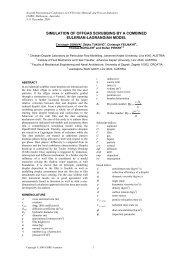
Figure 1: Experimental apparatus for the single pulse<br />
electromagnetic force experiment.<br />
Figure 2: Change in the observed coil currents with time.<br />
EXPERIMENTS<br />
Our experiments consisted <strong>of</strong> two parts. The first one was<br />
single pulse electromagnetic force experiment to confirm<br />
that a liquid metal <strong>jet</strong> can be broken up by applying the<br />
electromagnetic force. The second one was intermittent<br />
electromagnetic force experiment to fabricate <strong>uniformly</strong><br />
<strong>sized</strong> <strong>droplets</strong> <strong>from</strong> a <strong>capillary</strong> <strong>jet</strong>.<br />
Copyright © 2009 CSIRO Australia 2<br />
Single Pulse Electromagnetic Force<br />
Experimental Setup<br />
Fig.1 shows a schematic <strong>of</strong> an experimental setup. Molten<br />
gallium was heated and issued <strong>from</strong> the nozzle with mean<br />
axial <strong>jet</strong> velocity <strong>of</strong> 1.4m/s. The circuit including the<br />
capacitor, which was fully charged in advance, was<br />
shorted in order to apply a high current instantaneously to<br />
the single turn coil around the <strong>jet</strong>. Capacitance <strong>of</strong> the<br />
circuit could be selected <strong>from</strong> 4.7, 10.0, and 14.7mF,<br />
leading to a change <strong>of</strong> the coil current. To prevent<br />
oxidation <strong>of</strong> the metal surface, the experiment was run in<br />
argon atmosphere. Artem’ev and Kochetov (1991) pointed<br />
out that the breakup phenomena <strong>of</strong> a gallium <strong>jet</strong> was not<br />
affected by a surrounding gas <strong>of</strong> less than 0.2-0.3% in<br />
oxygen concentration. Shapes <strong>of</strong> the <strong>jet</strong> surface were<br />
captured by the high speed camera and the coil current<br />
was measured by a current probe. Fig.2 shows the change<br />
in the coil current with time. In the case <strong>of</strong> 14.7mF, the<br />
peak current <strong>of</strong> more than 7kA was applied to the coil.<br />
The mechanism <strong>of</strong> the breakup by the electromagnetic<br />
force is as follows: Magnetic field around the coil and<br />
eddy current in the liquid metal <strong>jet</strong> are induced by the coil<br />
current. As a result <strong>of</strong> interaction <strong>of</strong> the magnetic field and<br />
the eddy current ( ), Lorentz force is generated<br />
within the liquid metal. Fluid flow <strong>of</strong> the <strong>jet</strong> is disturbed<br />
and fluctuated by the force, and as the fluctuation grows,<br />
the liquid <strong>jet</strong> is going to be broken up.<br />
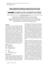
Experimental Results<br />
The serial photographs <strong>of</strong> the gallium <strong>jet</strong> are shown in<br />
Fig.3. The single pulse electromagnetic force was applied<br />
at 0ms. Firstly, surface fluctuation generated by the force<br />
was very small. After 10ms or more, small de<strong>formation</strong> <strong>of</strong><br />
the surface can be observed on the photographs. As the<br />
fluctuation grew, the <strong>jet</strong> was broken up at the downstream<br />
position. The shape <strong>of</strong> the free surface seemed to be<br />
axisymmetric. The breakup length and time required to<br />
breakup <strong>of</strong> the <strong>capillary</strong> <strong>jet</strong> became shorter with the<br />
increase in capacitance. In this experiment, it was<br />
confirmed that the single pulse electromagnetic force<br />
could disturb and break up the molten metal <strong>jet</strong> effectively.<br />
Intermittent electromagnetic force experiment<br />
Experimental Setup<br />
In order to fabricate <strong>uniformly</strong> <strong>sized</strong> <strong>droplets</strong>, an<br />
intermittent electromagnetic force was applied to a molten<br />
Figure 3: Serial photographs <strong>of</strong> the breakup <strong>of</strong> the gallium <strong>jet</strong> (left: 4.7mF, center: 10.0mF, right: 14.7mF).
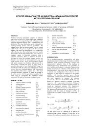
Figure 4: Schematic diagram <strong>of</strong> the droplet generator.<br />
Figure 5: Schematic diagram <strong>of</strong> the modulated current.<br />
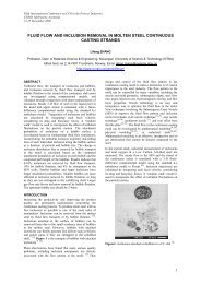
Figure 6: Photographs <strong>of</strong> the <strong>formation</strong> <strong>of</strong> the gallium<br />
<strong>droplets</strong> by the intermittent electromagnetic force.<br />
metal <strong>jet</strong>. Fig. 4 shows schematic diagrams <strong>of</strong> the<br />
experimental setup. Same as before, molten gallium was<br />
used as a liquid metal and images <strong>of</strong> the <strong>jet</strong> were taken by<br />
the high speed camera. The droplet generator consisted <strong>of</strong><br />
the induction coil and the concentrator. The concentrator,<br />
which was made <strong>of</strong> copper, had a tubular structure with an<br />
inward projection part on the inner surface. In addition,<br />
the concentrator was split longitudinally into two halves,<br />
which was insulated <strong>from</strong> each other. The concentrator<br />
was used to concentrate the electromagnetic force to a<br />
small region <strong>of</strong> the <strong>jet</strong> adjacent to the projection part. AC<br />
current <strong>of</strong> 51.3A rms and 3.06MHz in base frequency, f base,<br />
was applied to the coil. The current was modulated as<br />
square pulses intermittently and the modulating frequency,<br />
f mod, could be changed <strong>from</strong> 200 to 1000Hz (see Fig. 5).<br />
Copyright © 2009 CSIRO Australia 3<br />
Experimental Results<br />
Figure 6 shows photographs <strong>of</strong> experimental results. In the<br />
case ‘without EMF’, the <strong>jet</strong> didn’t break up at equal<br />
interval. In the case that the modulating frequency was<br />
200Hz, the <strong>jet</strong> broke up into <strong>droplets</strong> at equal interval;<br />
however, there were some small satellite <strong>droplets</strong> between<br />
the main <strong>droplets</strong>. The satellite <strong>droplets</strong> were formed at a<br />
neck part <strong>of</strong> the <strong>jet</strong> between the main <strong>droplets</strong>. It becomes<br />
a problem because the satellite <strong>droplets</strong> reduce the<br />
production yield <strong>of</strong> the <strong>uniformly</strong> <strong>sized</strong> particles. In the<br />
case <strong>of</strong> 320Hz, the <strong>jet</strong> broke up into <strong>uniformly</strong> <strong>sized</strong><br />
<strong>droplets</strong> at equal interval, which corresponded directly to<br />
an optimal wavelength due to a natural instability <strong>of</strong> a<br />
liquid <strong>jet</strong> (Weber, 1931). The optimal wavelength λ is<br />
expressed as:<br />
In this experiment, the optimal wavelength was 4.45mm,<br />
which corresponded to the modulating frequency <strong>of</strong><br />
309Hz. Thus, the <strong>jet</strong> could be broken up into <strong>uniformly</strong><br />
<strong>sized</strong> <strong>droplets</strong> effectively, by adjusting the intermittent<br />
electromagnetic force interval close to optimal wavelength.<br />
In the case <strong>of</strong> 500 Hz, the <strong>jet</strong> didn't appear to break up at<br />
equal intervals because the frequency <strong>of</strong> droplet <strong>formation</strong><br />
was too high, leading to coalescence.<br />
NUMERICAL SIMULATION<br />
Electromagnetic Force Analysis<br />
In order to estimate the electromagnetic force generated by<br />
the single pulse experiments, the electromagnetic field<br />
analysis was conducted by use <strong>of</strong> a commercial code<br />
JMAG (JSOL Corp.). Fig.7 shows the calculation domain.<br />
Assumptions used in the calculation are as follows:<br />
1. The system is axisymmetric.<br />
2. Flow <strong>of</strong> the liquid metal does not affect the magnetic<br />
field.<br />
3. The surface <strong>of</strong> the gallium <strong>jet</strong> near the coil is fixed,<br />
namely, the diameter <strong>of</strong> the <strong>jet</strong> is constant and equal to<br />
the nozzle diameter.<br />
The second assumption is reasonable because the<br />
magnetic Reynolds number, Re m, <strong>of</strong> the system is less than<br />
10 -2 . The first and third assumptions are not trivial at this<br />
stage, so they shall be reviewed later in the present paper.<br />
Figure 7: Schematic diagram <strong>of</strong> the calculation domain.<br />
phase liquid gas<br />
material gallium argon<br />
density (kg m -3 ) 6.09 ×10 3 1.62<br />
viscosity (Pa s) 2.04×10 -3 2.13×10 -5<br />
surface tension (N m -1 ) 0.718 -<br />
electrical conductivity (S m -1 ) 3.85×10 6 -<br />
Table 1: Properties <strong>of</strong> materials.<br />
(1)
Properties used in the numerical simulations are shown in<br />
Table 1. The observed coil currents (Fig.2) were used as<br />
current conditions in the calculation.<br />
Fluid Flow Analysis<br />
Numerical simulations on the breakup <strong>of</strong> the <strong>capillary</strong> <strong>jet</strong><br />
is carried out by use <strong>of</strong> a commercial <strong>CFD</strong> code FLUENT<br />
(ANSYS, Inc.). In the calculations, the Volume Of Fluid<br />
(VOF) method proposed by Hirt and Nichols (1981) was<br />
used to track the free surface <strong>of</strong> the <strong>jet</strong>. The VOF is<br />
designed for two (or more) immiscible fluids where the<br />
position <strong>of</strong> the interface between the fluids is <strong>of</strong> interest.<br />
In this model, a single set <strong>of</strong> momentum equation is shared<br />
by the fluids. The properties <strong>of</strong> the mixed fluid are<br />
determined by the presence <strong>of</strong> the component phases in<br />
each control volume.<br />
The scalar value <strong>of</strong> α 2 is defined as the ratio <strong>of</strong> the volume<br />
<strong>of</strong> the liquid over the total fluid volume. The transport<br />
equation <strong>of</strong> the volume <strong>of</strong> fraction α 2 is as follows:<br />
where α 2 has the value 1 for liquid phase and 0 for gas<br />
phase. The scalar value α 2 is used to determine the<br />
properties <strong>of</strong> the mixed fluid in the following manner:<br />
A single momentum equation, which is dependent on the<br />
properties <strong>of</strong> the mixed fluid, is solved throughout the<br />
domain.<br />
The surface tension model implemented in FLUENT is the<br />
continuum surface force (CSF) model proposed by<br />
Brackbill et al. (1992). With this model, an additional<br />
force due to surface tension is considered as a source term<br />
in the momentum equation. The pressure drop across the<br />
interface between the two fluids is<br />
The curvature κ is defined in terms <strong>of</strong> the gradient in the<br />
volume fraction α 2 as follows:<br />
The Reynolds number <strong>of</strong> the <strong>jet</strong> was<br />
Therefore, the flow was turbulent and a realizable k-ε<br />
model was used in the simulation.<br />
The time derivatives were discretized by an Euler implicit<br />
scheme and the convection terms are discretized by the<br />
quadratic upwind interpolation (QUICK) scheme. An<br />
Euler explicit with the geometric reconstruction scheme<br />
was used for the VOF calculation (Fluent Inc., 2006). The<br />
PISO algorithm was adopted for pressure–velocity<br />
coupling.<br />
The electromagnetic force obtained by the electromagnetic<br />
field analysis was assigned as a source term <strong>of</strong> the Navier-<br />
Stokes equation in the fluid flow calculation.<br />
RESULTS AND DISCUSSION<br />
Breakup <strong>of</strong> Capillary Jet by Natural Disturbance<br />
Firstly, a numerical simulation <strong>of</strong> breakup <strong>of</strong> <strong>capillary</strong> <strong>jet</strong><br />
without the electromagnetic force was carried out in order<br />
to estimate an accuracy <strong>of</strong> the fluid flow analysis. Fig.8<br />
shows the experimental result and the calculation results.<br />
The breakup length <strong>of</strong> the <strong>jet</strong> obtained by the simulation<br />
Copyright © 2009 CSIRO Australia 4<br />
(2)<br />
(3)<br />
(4)<br />
(5)<br />
(6)<br />
Figure 8: Breakup <strong>of</strong> the <strong>capillary</strong> <strong>jet</strong> by a growth <strong>of</strong><br />
natural disturbance (without an electromagnetic force).<br />
Figure 9: The Ohnesorge chart.<br />
was shorter than the experiment (see Table 2), however<br />
the behaviour <strong>of</strong> the breakup was quite similar. As<br />
mentioned before, the optimal wavelength <strong>of</strong> perturbation<br />
on the <strong>capillary</strong> <strong>jet</strong>, which has the fastest growth rate, is<br />
4.45mm in the present condition. The scale <strong>of</strong> the optimal<br />
wavelength is indicated in Fig.8(b). It can be seen <strong>from</strong> the<br />
figure that the wavelength <strong>of</strong> the <strong>capillary</strong> <strong>jet</strong> obtained by<br />
the numerical simulation coincides with the theoretical<br />
one. Pressure in the thinner part <strong>of</strong> the <strong>jet</strong> (‘neck’) was<br />
higher than the other part due to the Laplace equation<br />
(Eq.4).<br />
Ohnesorge (1936) firstly pointed out that the breakup<br />
phenomena could be classified into several different<br />
regions on a graph <strong>of</strong> the Ohnesorge number versus the<br />
Reynolds number. The Ohnesorge number <strong>of</strong> the gallium<br />
<strong>jet</strong> were estimated as<br />
According to the Ohnesorge chart (Fig.9; Lefebvre, 1989),<br />
the condition <strong>of</strong> the present study laid on the sinuous wave<br />
region. However, the shape <strong>of</strong> the free surface seemed to<br />
be axisymmetric <strong>from</strong> observation <strong>of</strong> the serial<br />
photographs taken by the high speed camera (Fig.3). Pan<br />
and Suga (2006) indicated that the dilational waves were<br />
still very dominant in the 1st wind-induced region<br />
although the small sinuous waves existed. This means that<br />
the <strong>jet</strong> was not axisymmetric in a precise sense. The<br />
discrepancy <strong>of</strong> the breakup length between the experiment<br />
and the simulation may arise <strong>from</strong> the assumption <strong>of</strong><br />
axisymmetric used in the simulation.<br />
(7)
Figure 10: Electromagnetic force field (14.7mF).<br />
Figure 11: Change in the electromagnetic force with time.<br />
Electromagnetic Force<br />
Figure 10 shows the calculation results <strong>of</strong> electromagnetic<br />
force fields for the single pulse electromagnetic force<br />
experiment <strong>of</strong> 14.7mF in capacitance. At 27.5µs, the<br />
electromagnetic force pointed in a radially-inward<br />
direction, and at 290µs, the direction was changed into the<br />
opposite direction.<br />
Figure 11 shows the temporal change in a radial component<br />
<strong>of</strong> the electromagnetic force on the free surface at the<br />
same z position <strong>of</strong> the coil. The maximum value <strong>of</strong> the<br />
force exceeded 40MN/m -3 in the case <strong>of</strong> 14.7mF in<br />
capacitance, which is much higher than the value <strong>of</strong><br />
gravitational force, 60kN/m -3 .<br />
Breakup <strong>of</strong> Capillary Jet by Electromagnetic Force<br />
The calculation results <strong>of</strong> the breakup by the single pulse<br />
electromagnetic force were shown in Fig.12. By<br />
comparison with the experimental results (Fig.3), it can be<br />
said that the agreement between the two is good. The<br />
Copyright © 2009 CSIRO Australia 5<br />
Exp. Cal.<br />
0mF (without EM force) 55-70mm 50-60mm<br />
4.7mF 48.7mm 38.5mm<br />
10.0mF 40.3mm 32.2mm<br />
14.7mF 37.3mm 28.6mm<br />
Table 2: Breakup length <strong>of</strong> the <strong>jet</strong>.<br />
Figure 13: Region affected by the electromagnetic force<br />
(14.7mF).<br />
Figure 14: Pressure distribution (left) and the free surface<br />
<strong>of</strong> the <strong>jet</strong> (right) near the coil (14.7mF).<br />
breakup lengths <strong>of</strong> the <strong>jet</strong> are summarized in Table 2. The<br />
simulations gave shorter breakup length than the<br />
experiments, however the dependency <strong>of</strong> the length on the<br />
electromagnetic force was similar.<br />
Figure 13 shows a distribution <strong>of</strong> a passive scalar, which<br />
represents the region affected by the electromagnetic force.<br />
The <strong>jet</strong> was broken up just at the region. This indicated<br />
that the surface fluctuation was fixed on the surface, and<br />
transferred with the flow. Arai and Amagai (1999) also<br />
reported the same results <strong>of</strong> a fixed wave on the <strong>jet</strong> surface<br />
observed by their experiment.<br />
Pressure distribution and the free surface <strong>of</strong> the <strong>jet</strong> near the<br />
coil are shown in Fig.14. The pressure in the <strong>jet</strong> was<br />
Figure 12: Numerical simulation <strong>of</strong> the breakup <strong>of</strong> the gallium <strong>jet</strong> (left: 4.7mF, center: 10.0mF, right: 14.7mF).
Figure 15: Axial velocity deviation <strong>from</strong> the initial<br />
velocity along the center axis.<br />
increased by the electromagnetic pinch force, and then the<br />
pressure became negative as the force direction was<br />
changed into the opposite direction. In spite <strong>of</strong> the drastic<br />
change <strong>of</strong> the pressure, the shape <strong>of</strong> the free surface<br />
showed little change. The initial amplitude <strong>of</strong> the<br />
perturbation can be estimated by the following equation<br />
(Weber, 1931):<br />
where z is the breakup position. By substitution <strong>of</strong><br />
parameters into Eq.(8), the initial amplitude was estimated<br />
as A 0 = 0.8µm and it was very small compared to the <strong>jet</strong><br />
diameter. So, the <strong>jet</strong> can be considered as ‘a solid thin<br />
column’ with the fixed surface in the electromagnetic<br />
analysis.<br />
Figure 15 shows the axial velocity deviation <strong>from</strong> the<br />
velocity before applying the electromagnetic force. The<br />
negative value means that the axial velocity is slower than<br />
the velocity without electromagnetic force. At 30µs, the<br />
axial velocity in the upstream region above the coil (z <<br />
3mm) became slower and it became faster in the<br />
downstream region (z > 3mm). The velocity deviation did<br />
not disappear after applying the electromagnetic force at<br />
550µs and it was transferred with the flow to the<br />
downstream. This velocity deviation in the up and<br />
downstream results in the drainage <strong>of</strong> fluid <strong>from</strong> the center<br />
position and the diameter <strong>of</strong> the position becomes thinner<br />
slightly. The <strong>jet</strong> pressure at the position will be increased<br />
with decreasing in the diameter because <strong>of</strong> the Laplace<br />
pressure (Eq. 4); it will promote the fluid drainage more.<br />
This is the process <strong>of</strong> the <strong>jet</strong> breakup by the single pulse<br />
electromagnetic force.<br />
CONCLUSION<br />
In the single pulse electromagnetic force experiment, it<br />
was confirmed that the single pulse electromagnetic force<br />
could fluctuate the free surface <strong>of</strong> the <strong>jet</strong> and break up the<br />
<strong>jet</strong>. In the intermittent electromagnetic force experiment, it<br />
was found that the <strong>jet</strong> was broken up into mono-<strong>sized</strong><br />
<strong>droplets</strong> when the modulation frequency <strong>of</strong> intermittent<br />
electromagnetic forces was adjusted to the optimal<br />
wavelength. The numerical simulation was carried out to<br />
simulate the breakup phenomenon <strong>of</strong> the <strong>jet</strong> by applying<br />
the single pulse electromagnetic force. The simulation<br />
results were compared with the experiments and the<br />
agreement between the two was good.<br />
Copyright © 2009 CSIRO Australia 6<br />
(8)<br />
ACKNOWLEDGMENT<br />
This work was supported by Japan Society for the<br />
Promotion <strong>of</strong> Science (JSPS), Grant-in-Aid for Scientific<br />
Research (A) (No. 18206078)<br />
REFERENCES<br />
ACQUAVIVA, P., CHEN, C., CHUN, J., and ANDO,<br />
T., (1997), “Thermal modelling <strong>of</strong> deposit solidification in<br />
uniform droplet spray forming”, J. Manufacturing Scis.<br />
Eng., 119, 332-340.<br />
ARAI, M. and AMAGAI, K., (1999), “Surface wave<br />
transition before breakup on a laminar liquid <strong>jet</strong>”, Int. J.<br />
Heat & Fluid Flow, 20, 507-512.<br />
ARTEM’EV, B. V. and KOCHETOV, S. G., (1991),<br />
“Capillary breakup <strong>of</strong> a liquid-metal <strong>jet</strong> in an oxidizing<br />
medium”, J. Eng. Phys. Thermophys., 60, 425-429.<br />
BOJAREVICS, V., TANIGUCHI, S., and<br />
PERICLEOUS, K., (2006), “Droplet generation with<br />
modulated AC electromagnetic field at nozzle exit”, Proc.<br />
5 th Int. Symp. on Electromagnetic Processing <strong>of</strong> Materials<br />
(EPM2006), Sendai, Japan, October 23-27, 259-264.<br />
BRACKBILL, J. U., KOTHE, D. B., and ZEMACH, C,<br />
(1992), “A continuum method for modelling surface<br />
tension”, J. Comput. Phys., 100, 335–354.<br />
EGGERS, J., (1997), “Nonlinear dynamics and breakup<br />
<strong>of</strong> free-surface flows”, Reviews Modern Phys., 69, 865-<br />
929.<br />
FLUENT Inc., (2006), “Fluent 6.3 User's Guide”,<br />
Chapter 23.<br />
HIRT, C. W. and NICHOLS, B. D., (1981), “Volume <strong>of</strong><br />
fluid (VOF) method for the dynamics <strong>of</strong> free boundaries”,<br />
J. Comput. Phys., 39, 201-225.<br />
IMANISHI, K., SHIMASAKI, S., TANIGUCHI, S., and<br />
BOJAREVICS, V., (2008), “Manufacturing <strong>of</strong> spherical<br />
silicon for solar cell by electromagnetic pinch force”, Proc.<br />
3 rd Asian Workshop & Summer School on Electromagnetic<br />
Processing <strong>of</strong> Materials (Asian-EPM2008), Shanghai,<br />
China, October 13-15, 211-214.<br />
LEFEBVRE, A. H., (1989), “Atomization and Sprays”,<br />
Hemisphere, New York.<br />
MINEMOTO, T., OKAMOTO, C., OMAE, S.,<br />
MUROZONO, M., TAKAKURA, H., and HAMAKAWA,<br />
Y., (2005), “Fabrication <strong>of</strong> spherical silicon solar cells<br />
with semi-light-concentration system”, Jpn. J. Appl. Phys.,<br />
44, 4820-2834.<br />
OHNESORGE, W., (1936), “Formation <strong>of</strong> drops by<br />
nozzles and breakup <strong>of</strong> liquid <strong>jet</strong>s”, Z. angew. Math.<br />
Mech., 16, 355-358.<br />
PAN, Y. and SUGA, K., (2006), “A numerical study on<br />
the breakup process <strong>of</strong> laminar liquid <strong>jet</strong> into a gas”, Phys.<br />
Fluids, 18, 052101.<br />
RAYLEIGH, L., (1879), “On the instability <strong>of</strong> <strong>jet</strong>s”,<br />
Proc. London Math. Soc., 10, 4-13.<br />
TAKAGI, K., MASUDA, S., SUZUKI, H., and<br />
KAWASAKI, A., (2006), “Preparation <strong>of</strong> mono<strong>sized</strong><br />
copper micro particles by pulsated orifice ejection<br />
method”, Mater. Trans., 47, 1380-1385.<br />
WEBER, C., (1931), “Zum Zerfall eines<br />
Flüssigkeitsstrahles”, Z. angew. Math. Mech., 11, 136-154.<br />
YANG, X., FENG, J., LIU C., and SHEN, J., (2006),<br />
“Numerical simulation <strong>of</strong> <strong>jet</strong> pinching-<strong>of</strong>f and drop<br />
<strong>formation</strong> using an energetic variational phase-field<br />
method”, J. Comput. Phys., 218, 417-428.