INTEGRA II Insert - Rika
INTEGRA II Insert - Rika
INTEGRA II Insert - Rika

You also want an ePaper? Increase the reach of your titles
YUMPU automatically turns print PDFs into web optimized ePapers that Google loves.
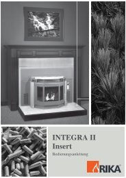
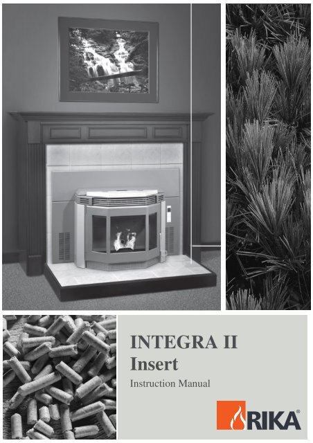
<strong>INTEGRA</strong> <strong>II</strong><br />
<strong>Insert</strong><br />
Instruction Manual<br />
- 1 -
- 2 -
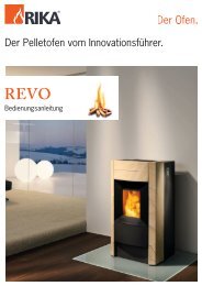
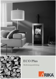
DIMENSIONS<br />
- 3 -
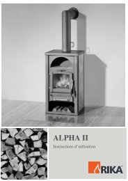
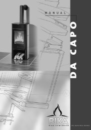
CONTROL MOTHERBOARD – DIAGRAM<br />
a<br />
PE yellow/green<br />
N blue<br />
L brown<br />
b<br />
1 HAL-Sensor-Flue gas fan<br />
2 Control panel<br />
3 Pellet/Tele-Control<br />
4 Airsensor<br />
5 Low limit switch<br />
6 High limit switch<br />
7 FKY 1<br />
8 FKY 2<br />
9 Alarm<br />
- 4 -<br />
I Power grid 230 VAC 50 Hz<br />
<strong>II</strong> Flue gas fan<br />
<strong>II</strong>I Convection fan<br />
IV Ignition<br />
V Auger motor<br />
VI Circulating<br />
V<strong>II</strong> Reserve<br />
PE yellow/green<br />
Control motherboard<br />
a Microfuse<br />
b Condenser<br />
A Bus 1<br />
B Bus 2<br />
C Bus 3
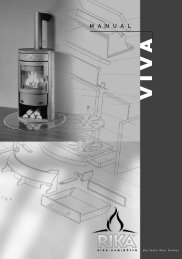
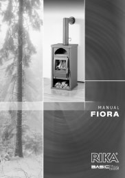
SPARE PART OVERVIEW<br />
- 5 -
SPARE PART OVERVIEW<br />
Pos Designation Article number<br />
31 Control panel B15092<br />
32 Adapter for flue gas fan Z19331<br />
33 HP bracket B15651<br />
34 Motor plate Z14592<br />
36 Door handle Z32944<br />
37 Container cover B11332<br />
38 Front casing (depending on model)<br />
39 Side casing (depending on model)<br />
40 Side casing control panel (depending on model)<br />
41 Cover Z32969<br />
42 Ceramic cover (depending on ceramic<br />
colour)<br />
43 Hose clamp 70-90mm 106155<br />
44 Temperature limiter top 104696<br />
45 Sintered bearing 102688<br />
46 Temperature limiter bottom 111636<br />
47 Screw motor 111635<br />
48 Cross-flow fan cpl. B15107<br />
49 Flue gas fan cpl. B16156<br />
50 Air sensor B15069<br />
51 Fuse 110696<br />
Mains cable Z32219<br />
Cable for ignition Z32217<br />
Cable for screw motor Z32218<br />
Cable for air sensor Z32215<br />
Cable for induced draught fan B15982<br />
Cable for temperature limiter bottom Z32214<br />
Pos Designation Article number<br />
1 Clamping ring Z11915<br />
2 Seal for temperature limiter bottom Z12388<br />
3 Screw conveyor B11326<br />
4 Trough cover Z14593<br />
5 Ash tray Z14907<br />
6 Flue plate top Z14912<br />
7 Flue plate bottom Z14913<br />
8 Flue gas fan motor 111581<br />
9 Closing plate B11417<br />
10 Combustion cavity Z32908<br />
11 Hinge bolt bottom B14917<br />
12 Hinge bolt top B14673<br />
13 Cleaning opening B11717<br />
14 Insulating plate Z14954<br />
15 Supply air flange Z18278<br />
16 Combustion chamber door Z30968<br />
Combustion chamber door cpl. B14672<br />
17 Glazing bead left Z19750<br />
18 Glazing bead right Z19751<br />
19 Glazing bead Z19752<br />
20 Door glass front Z14846<br />
21 Door glass side Z14847<br />
22 Hinge band Z14939<br />
23 Casing left (depending on model)<br />
24 Casing right (depending on model)<br />
25 Trim B14915<br />
26 Sealing strip D12 100485<br />
27 Flat gasket 103693<br />
28 Flat gasket 103693<br />
29 Ignition Z32147<br />
30 Motherboard B15152<br />
- 6 -
CONTENTS<br />
Dimensions ......................................................................................3<br />
Control Motherboard - Diagram .......................................................4<br />
Spare part overview......................................................................5-6<br />
Explanation of symbols ....................................................................8<br />
Technical data..................................................................................9<br />
Packaging .......................................................................................9<br />
1. IMPORTANT INFORMATION<br />
General warning and safety information ........................................10<br />
2. WHAT ARE PELLETS? ................................................................10<br />
Specification for high-quality pellets...............................................10<br />
Pellet storage.................................................................................10<br />
3. AUTOMATIC SAFETY FUNCTIONS<br />
Power failure..................................................................................11<br />
Overheating ...................................................................................11<br />
Low temperature switch off ............................................................11<br />
4. INSTALLING THE STOVE<br />
General information .......................................................................12<br />
Example installation.......................................................................12<br />
Floor protection..............................................................................12<br />
Safety distances.............................................................................12<br />
Electrical connection......................................................................13<br />
Combustion air...............................................................................13<br />
Feed of external combustion air ..............................................13<br />
5. FITTING THE PANELLING, OPTIONS<br />
General .....................................................................................14<br />
Side panel .....................................................................................14<br />
Rib elements..................................................................................14<br />
Wall panel ................................................................................14-15<br />
6. OPERATION<br />
Basic information ...........................................................................16<br />
Control and internal control unit – function.....................................16<br />
Internal control unit..................................................................16<br />
7. UNIT COMMISSION ING/CONTROL<br />
PROGRAMMING/CONTROL OPTIONS<br />
General .....................................................................................17<br />
First commissioning/program settings.......................................17-19<br />
MAIN MENU OPERATING AREAS<br />
- Standby-mode.......................................................................20<br />
- Manual operation...................................................................20<br />
- Automatic operation ..............................................................20<br />
Start manual operation (ON-Modus)..............................................20<br />
Start automatic operation (TM-Modus) ..........................................21<br />
SHUT DOWN UNIT ......................................................................21<br />
Shut down from “Manual operation (ON)”..................................21<br />
Shut down unit from automatic operation ..................................22<br />
Automatic stop controlled by heating time .........................22<br />
Automatic stop, manual .....................................................22<br />
Shut down by operating mode in Standby..................................22<br />
Pellet control (optional) room temperature sensor......................22<br />
- 7 -<br />
E N G L I S H
E N G L I S H<br />
8. ELECTRICAL IGNITION<br />
Pre-heating without electrical ignition.........................................23<br />
Some field values .......................................................................23<br />
Fuel feed ....................................................................................23<br />
9. CLEANING AND MAINTENANCE<br />
Basic Information........................................................................24<br />
Cold Hand .................................................................................24<br />
Cleaning the burn pot .................................................................24<br />
Cleaning the grate door glass.....................................................24<br />
Heat exchanger..........................................................................24<br />
Ashtray .......................................................................................25<br />
Wood ash as a fertliser...............................................................25<br />
Glass cleaning............................................................................25<br />
Flue gas outlets..........................................................................25<br />
Flue gas box...............................................................................25<br />
Flue gas fan housing ..................................................................26<br />
Fuel container.............................................................................26<br />
Door seal....................................................................................26<br />
Flue connection..........................................................................26<br />
Air sensor ...................................................................................26<br />
10. FAULTS – CAUSES – SOLUTIONS<br />
Faults – Causes - Solutions...................................................27-28<br />
Error messages control ..............................................................28<br />
11. Attachment<br />
Navigation to programme the internal control system ................29<br />
List of headings and abbreviations .............................................30<br />
12. WARRANTY<br />
Installation certificate for <strong>Rika</strong> pellet air heating device ..............31<br />
We guarantee ............................................................................32<br />
Commissioning report ...........................................................35-36<br />
Subject to technical and visual changes; setting and printing errors excepted.<br />
EXPLANATION OF SYMBOLS<br />
Important information<br />
Practical advice<br />
Use the plan<br />
- 8 -
TECHNICAL DATA<br />
TECHNICAL DATA<br />
Height [mm] 600<br />
Width [mm] 718<br />
Depth of the corpus [mm] 653<br />
Weight [kg] 120<br />
Flue pipe outlet diameter [mm] 100<br />
Heat output range [kW] 2,4 – 9,0<br />
Room heating capacity (m3)<br />
depending on house insulation<br />
[m3] 50 - 230<br />
Fuel consumption<br />
[kg/h]<br />
ca.<br />
0,6 – 2,2<br />
Pellet container capacity [kg] ca. 40<br />
Mains connection [V]; [Hz] 230; 50<br />
Average electrical power<br />
consumption<br />
[W] ca.100<br />
Protection [A] 1.6 T<br />
Efficiency [%] 88,6<br />
CO2 content [%] 9,3<br />
CO emission rel. 13% O [mg/Nm 3 ] 109<br />
Dust emissions [mg/Nm 3 ] 17<br />
Exhaust mass flow [g/s] 7,0<br />
Exhaust temperature [°C] 168,9<br />
Draught requirement [Pa] 0<br />
The owner of the small heating system or the<br />
authorised person for the small heating system must<br />
keep the technical documentation in a safe place<br />
and present it to the local authority or the chimney<br />
sweep if required.<br />
Please observe the national and European<br />
standards, as well as the local regulations that are<br />
applicable for the installation and operation of this<br />
heating appliance.<br />
PACKAGING<br />
Your first impression is important to us!<br />
- The packaging for your new stove provides<br />
excellent protection against damage. However<br />
damage to the stove and accessories can occur<br />
during transport.<br />
Therefore please check that your stove is undamaged<br />
and that all parts are there on receipt!<br />
- The packaging for your new stove generally has no<br />
effect on the environment.<br />
The box and the film (PE) can be safely taken to the<br />
local council waste disposal depot for recycling.<br />
- 9 -<br />
E N G L I S H
E N G L I S H<br />
1. IMPORTANT INFORMATION<br />
GENERAL WARNING AND SAFETY<br />
INSTRUCTIONS<br />
The general introductory warning information must<br />
be followed.<br />
● Read the whole of the manual thoroughly before<br />
commissioning the stove.<br />
● Only approved transport aids with adequate load<br />
bearing capacity must be used for transporting your<br />
stove.<br />
● Your stove is not suitable for use as a ladder or<br />
scaffold.<br />
● Thermal energy is produced by burning fuel; this<br />
leads to the surface of the stove, the doors, the door<br />
and operating handles, the door glasses, the flue<br />
pipes and possibly the front wall of the stove<br />
becoming very hot. Avoid touching these parts<br />
without wearing the relevant protective clothing or<br />
using the relevant means (cold hand).<br />
2. WHAT ARE PELLETS?<br />
Pellets are made from wooden waste, from sawmills<br />
and planing workshops, as well as from residue from<br />
forestry operations. These “starting products” are<br />
crushed, dried, and pressed into Pellet “Fuel”<br />
without any bonding agent.<br />
SPECIFICATIONS FOR HIGH<br />
QUALITY PELLETS<br />
Calorific Value: 5.3 kWh/kg<br />
Density: 700 kg/m3<br />
Water Content: Max. 8% of the weight<br />
Ash proportion: Max. 1% of the weight<br />
Diameter: 5 - 6.5mm<br />
Length: Max. 30mm<br />
Contents: 100% wood untreated and without<br />
any bonding agents added (bark<br />
proportion max. 5%)<br />
Packaging: In bags, made of environmentally<br />
neutral or biologically degradable<br />
plastic, or from paper (2-3 layers /<br />
similar to cement packaging)<br />
- 10 -<br />
● Make children aware of the danger and keep them<br />
away from the stove when in use.<br />
● Placing non heat resistant objects on the stove or<br />
nearby is prohibited.<br />
● Do not lay washing on the stove to dry.<br />
● Stands for drying items of clothing or suchlike<br />
must be set up at an adequate distance from the<br />
stove – fire hazard!<br />
● Working with easily combustible and explosive<br />
materials in the same or adjoining room to the stove<br />
is prohibited when the stove is on.<br />
● ATTENTION!!<br />
In cause of safety reason please do not open the<br />
combustion chamber door during operation!<br />
● CAUTION when filling the pellet hopper. The<br />
opening of the pellet hopper is sufficient to ensure<br />
problem-free filling. Ensure that no pellets fall on the<br />
convection ribs and the hot stove body. This can<br />
otherwise lead to heavy smoke formation.<br />
Please ask your pellet stove dealer for tested fuel and<br />
a list of monitored fuel manufacturers. Using poor<br />
quality or prohibited pellet fuel will have a negative<br />
effect on the function of your pellet stove and can also<br />
lead to the warranty becoming null and void, as well as<br />
the product liability connected with this. Observe<br />
waste incineration legislation.<br />
Burn only pellets that have been tested.<br />
PELLET STORAGE<br />
In order to guarantee problem free burning of the<br />
wooden pellets, it is necessary to store the fuel as<br />
dry as possible and free from impurities.
3. AUTOMATIC SAFETY FUNCTION<br />
POWER FAILURE<br />
After a short power failure the operating functions<br />
that were set before the power failure are continued.<br />
ON mode (manual operation). The control switches<br />
to the ST (Start Phase) and the unit then re-runs in<br />
ON operation.<br />
TM mode (automatic operation). The control<br />
switches to the ST (Start Phase) and the unit then<br />
re-runs in TM operation.<br />
SB mode (operational readiness, standby<br />
operation). After two seconds the control re-runs in<br />
the SB operation.<br />
On power failure a small amount of smoke may be<br />
emitted. This does not last for more than three to<br />
five minutes and does not represent a safety risks.<br />
OVERHEATING<br />
A temperature safety switch (STL) switches the<br />
stove off automatically if it overheats.<br />
A taking-out-of-service program (cleaning, follow-up<br />
phase) is performed. The stove must be restarted<br />
depending on the pre-set mode.<br />
CAUTION: If overheating has occurred then<br />
maintenance or cleaning work must be carried out.<br />
LOW TEMPERATURE SWITCH OFF<br />
If the stove cools down below a minimum<br />
temperature, then the stove will switch off. This<br />
switch off can also occur if pre-heating is too slow.<br />
- 11 -<br />
E N G L I S H
E N G L I S H<br />
4. INSTALLING THE STOVE<br />
GENERAL INFORMATION<br />
The stove must be connected to a chimney that is<br />
approved for solid fuels. The chimney must have a<br />
diameter of at least 120 mm.<br />
The flue system is based on negative pressure in<br />
the combustion chamber and a slight overpressure<br />
on the flue gas outlet. It is therefore important that<br />
the flue gas connection is fitted correctly and is<br />
airtight.<br />
Only use heat resistant sealing materials, as well as<br />
the relevant sealing bands, heat resistant silicon and<br />
mineral wool.<br />
Only authorised technical personnel must carry out<br />
assembly work.<br />
In addition you must ensure that the flue tube does<br />
not project into the free cross section of the<br />
chimney.<br />
NOTE: Please follow the regionally valid building<br />
regulations. Contact your master chimney sweep for<br />
information on this.<br />
EXAMPLE INSTALLATION<br />
When installing the Integra fireplace insert observe<br />
the appropriate regulations for the construction of<br />
fireplaces.<br />
The fireplace insert should only be installed in<br />
approved prefabricated or masonry fireplaces.<br />
- In any case, a direct and tight connection<br />
between the flue gas outlet and the chimney is<br />
required.<br />
- Furthermore, the appliance must be able to be<br />
removed for maintenance purposes.<br />
For the reasons mentioned above we recommend<br />
installing the appliance with a flexible stainless steel<br />
pipe.<br />
Procedure:<br />
1. Assemble the connecting plate to the chimney<br />
inlet - seal by using a self-adhesive sealant or<br />
silicone (up to 300 C).<br />
2. Determining the hose length:<br />
stretched length + 40 cm (approx.)<br />
3. Attach the flexible hose and seal with a heatresistant<br />
silicone<br />
4. Fit the base plate, partially insert the appliance<br />
into the fireplace opening and connect the hose<br />
MAKE SURE THE APPLIANCE IS SEATED<br />
CORRECTLY AND PROPERLY SEALED<br />
- prepare the electrical connection<br />
- assemble and insert the appliance<br />
- 12 -<br />
Only use approved<br />
flex steel pipes<br />
(contact you RIKA<br />
dealer).<br />
Wall panel<br />
Base plate<br />
Connecting plate<br />
FLOOR PROTECTION<br />
For flammable floor surfaces (wood, carpet, etc.) a<br />
glass, steel plate or ceramic underlay is required.<br />
SAFTEY DISTANCES<br />
(Measured from the outside of the stove)<br />
to flammable<br />
items<br />
non combustible<br />
floor protection<br />
to noncombustible<br />
items<br />
a 200 mm 100 mm<br />
b 800 mm 400 mm<br />
d 500 mm 500 mm<br />
measure in mm<br />
At installation all<br />
connections have<br />
to be airtight.
ELECTRICAL CONNECTION<br />
The stove is supplied with an approx. 2.5 m long<br />
connecting cable with a plug. The cable must be<br />
connected to a 230 V, 50 Hz electrical supply. The<br />
average electric power consumption is approx 100<br />
watts during heating. During the automatic ignition<br />
process (duration 10 minutes) approx. 350 watts.<br />
The connection cable must be laid so that any<br />
contact with hot or sharp edges external surfaces on<br />
the stove is avoided.<br />
When establishing the electrical connection to the left<br />
of the appliance, secure the cable in place and make<br />
sure that it does not come into contact with the flue<br />
pipe.<br />
COMBUSTION AIR<br />
Each combustion procedure requires oxygen or air.<br />
As a rule this combustion air is removed from the<br />
living area for individual stoves The air taken from<br />
the living area must be reintroduced. In modern<br />
houses, very tight fitting windows and doors mean<br />
that too little air flows back. This situation becomes<br />
problematic due to additional ventilation in the<br />
house (e.g. in the kitchen or WC).<br />
The suctioning in of combustion air is performed via<br />
the flue gas fan. The resulting combustion air and<br />
suctioning noises are normal operational noises that<br />
may occur at varying volumes depending on the<br />
chimney draught, output level or a dirty combustion<br />
trough – NOT A CAUSE FOR COMPLAINT!<br />
Minimum diameter<br />
5 cm / 2 inch<br />
- 13 -<br />
Feed of external combustion air<br />
● Steel, HT or flexible aluminium pipes must be<br />
used.<br />
● Minimum diameter 5 cm/2 inches.<br />
● For longer connection runs the diameter must be<br />
increased to approx. 10 cm after approx. 1 m.<br />
● The pipe should not be longer than approx. 4m<br />
in total to guarantee adequate air feed and not<br />
have too many bends.<br />
● Should the line lead into the open air, it must<br />
end with a vertical 90° downward elbow or with a<br />
wind guard.<br />
Should one or more of these conditions NOT be<br />
applicable then usually poor combustion will occur<br />
in the stove, as well as air underpressure in the<br />
apartment.<br />
Further it is possible to extract the combustion air<br />
directly from outside or from another room that is<br />
well ventilated (e.g. the cellar).<br />
Please observe:<br />
Your pellet stove works independent of the room air.<br />
Negative pressures in the set-up room are not<br />
permissible. Therefore the use of a safety device<br />
(e.g. differential pressure controller) in combination<br />
with room air facilities (e.g. ventilation system,<br />
exhaust extraction etc.) is stipulated.<br />
Wall<br />
E N G L I S H
E N G L I S H<br />
5. ASSEMBLY OF PANELS, OPTIONS<br />
GENERAL<br />
CAUTION! Only work on the unit when the mains plug<br />
has been disconnected.<br />
Your stove must be switched off and cooled before<br />
any work is performed.<br />
Do not allow objects (screws etc.) to fall into the fuel<br />
hopper – they can block the screw conveyor and<br />
damage the stove.<br />
SIDE PANEL<br />
1. <strong>Insert</strong> the side sections in the receiving seat<br />
provided on the bottom section.<br />
2. Push the side section against the stove until it is<br />
vertical.<br />
3. Then fasten with two screws in the pellet<br />
container<br />
Repeat on the other side of the stove.<br />
RIB ELEMENTS<br />
Proceed as follows when exchanging the upper<br />
and lower rib elements:<br />
1. Remove the warming plate<br />
2. Undo the mounting screws and remove the<br />
rib element (the new element is assembled<br />
using the same mounting screws).<br />
The lower rib element can only be exchanged<br />
BEFORE INSTALLING the fireplace box.<br />
The lower element is replaced in the same way<br />
(however the screws are removed from the<br />
underside).<br />
- 14 -<br />
WALL PANEL<br />
The wall panel is used for lining the fireplace<br />
opening around the fireplace insert. Two sizes<br />
are available (see image).
Assembly:<br />
First attach the left and right part of the panel to<br />
the appliance (2 bolts for each)<br />
Attach the upper part of the wall panel and<br />
secure it in place on the container wall using 2<br />
bolts for the side and 2 bolts for the centre.<br />
Attach the control board<br />
- 15 -<br />
Carefully insert the appliance into the fireplace<br />
opening until it is covered by the wall panel.<br />
E N G L I S H
E N G L I S H<br />
6. OPERATION<br />
BASIC INFORMATION<br />
The stove must only be started when fully fitted.<br />
Your pellet stove is exclusively for burning pellets<br />
made from wood of a controlled quality. Non-pelletised<br />
solid fuels (straw, maize, chopped matter etc.) are not<br />
permitted. Failure to adhere to these guidelines will<br />
make all guarantee and warranty claims null and void<br />
and could have a negative effect on the safety of your<br />
stove.<br />
When operated correctly your pellet stove cannot<br />
overheat. Improper operation can however shorten the<br />
life expectancy of the electric stove components (fan,<br />
motors and electric control) and is not permitted.<br />
CONTROL AND INTERNAL<br />
CONTROL UNIT - FUNCTION<br />
(Fig. 4, Part 20)<br />
Your pellet stove is fitted with a modern<br />
programmable microprocessor control.<br />
The individual functions of the appliance can be<br />
preset by the user via the internal control unit<br />
(keypad with operating display).<br />
The control (main board) and the control board may<br />
only be altered by trained specialist dealers or the<br />
service department. Improper handling of these<br />
parts leads to the guarantee and warranty becoming<br />
null and void.<br />
- 16 -<br />
INTERNAL CONTROL UNIT<br />
All settings and functions can be regulated via this<br />
unit.<br />
Fig 1. Internal operating unit, key layout<br />
DISPLAY PANEL:<br />
Display of operating state in illuminated text<br />
MENU:<br />
Navigation in and to the various sub-menu levels<br />
ENTER:<br />
Navigation in the main modes (SB, ON, TM) and<br />
confirmation of use inputs<br />
MINUS/PLUS:<br />
Decrease and increase of user values<br />
ON/OFF:<br />
Switching unit on and off<br />
For a graphical representation of the menu<br />
navigation of the program levels see Appendix.<br />
Possible operating ranges<br />
Your pellet stove can get predefined in 3 different<br />
operating states:<br />
- Manual operation (ON)<br />
- Automatic operation (TM)<br />
- Standby mode (SB)<br />
You can switch between the various operating types<br />
by pressing “ENTER”.
7. DEVICE COMMISSIONING / CONTROL PROGR AMMING / CONTROLOTIONS<br />
GENERAL<br />
● Check that the pellet hopper is full and the<br />
combustion chamber is clean and contamination<br />
free.<br />
CAUTION: During the ignition process the grate door<br />
must be closed. The electronic ignition does not work<br />
if the grate door is open.<br />
When the pellet hopper of the stove is filled for the<br />
first time, no pellets are conveyed to the burn pot for<br />
about 10 minutes. You can put a handful of pellets in<br />
the burn pot to avoid a new start process.<br />
FIRST COMMISSIONING/<br />
PROGRAMME SETTINGS<br />
After filling the pellet hopper and connecting the<br />
stove to the mains electrical supply, press the<br />
ON/OFF key on the internal operating unit and SB<br />
(Standby) is displayed.<br />
“SB” = standby operation<br />
Now program your control for your individual<br />
requirements as follows: (See page 29 for menu<br />
navigation). Two heating intervals can be<br />
programmed for each weekday. No heating times<br />
are programmed in the factory. Press “MENU” on<br />
the operating unit and the display shows the<br />
following:<br />
“MO” = Monday<br />
- 17 -<br />
Now press “ENTER” and the display shows:<br />
“S1” = start first heating time, 6 the<br />
number is the time in hours (0 to 23<br />
hours) e.g. see window 6 Hour.<br />
By pressing the “+” or “-” keys the heating time can<br />
be changed in hourly steps as required. The desired<br />
value is confirmed with “ENTER” and is then saved.<br />
The display shows<br />
“E1” = end of first heating time,<br />
By pressing the “+” or “-” keys the heating time can<br />
be changed in hourly steps as required. The desired<br />
value is confirmed with “ENTER” and is then saved.<br />
The display shows<br />
“S2” = start of second heating<br />
time,<br />
After entering the second heating time and<br />
confirming with “ENTER” the display shows<br />
“E2” = end of second heating time,<br />
After entering the switch off point of the second<br />
heating time and confirming with “ENTER” the new<br />
valued is saved and the display now shows:<br />
E N G L I S H
E N G L I S H<br />
On selecting the “MENU” key the display shows the<br />
following weekday:<br />
“TU” = Tuesday,<br />
Press the “ENTER” key to return to the starting point<br />
of the first heating time for Tuesday.<br />
Proceed to enter the rest of the heating times for the<br />
weekdays (Wednesday “WE”, Thursday “TH”, Friday<br />
“FR”, Saturday “SA”, Sunday “SU” as described<br />
above.<br />
After acknowledgement with “ENTER” of the E2<br />
value of Sunday (SU) and selection of “MENU” the<br />
display shows:<br />
“PS” (Power Start) = heating<br />
output during the programmed<br />
heating times (S1-E2, S2-E2).<br />
The number corresponds to the heating output in<br />
percent (0% equals minimum heating output, 100%<br />
equals maximum heating output).<br />
By pressing the “+” or “-” keys you can change the<br />
value of the heating output in 5% steps as required.<br />
The value is confirmed with “ENTER” and the<br />
display shows<br />
“PE” (Power End) = heating<br />
output between the programmed<br />
heating times (E1-S2).<br />
“OFF” indicates that the stove is switched off<br />
between the programmed heating times.<br />
The value “OFF” is achieved by pressing the “-” key<br />
until “OFF” is displayed.<br />
- 18 -<br />
If you want to maintain a specific heating output (low<br />
operation) between the programmed heating times<br />
you can set the required value by pressing the “+” or<br />
“-” keys.<br />
Press the “ENTER” key to save the PE value, the<br />
display shows:<br />
To improve combustion quality, automatic<br />
cleaning of the burn pot is programmed into the<br />
control process<br />
By pressing the “+” or “-” keys you can determine<br />
the desired time interval in 5 minute steps (The<br />
cleaning interval can be extended to 300 minutes,<br />
however we recommend a cleaning cycle of 60<br />
minutes). Confirm with “ENTER” and the display<br />
shows:<br />
VA<br />
1.28<br />
The number equals the heating<br />
output in percent (e.g. see window<br />
5%).<br />
“CL” = Clean<br />
the number indicates the time<br />
interval in minutes (e.g. see<br />
window 60 Minutes).<br />
This is the current software version<br />
of the control and is used for<br />
customer service reasons (display<br />
only).<br />
Now use “MENU” to access the internal clock and<br />
the following display appears:<br />
“H” = Hour the number indicates<br />
the hour (value range 0 to 23).
By pressing the “+” or “-” keys the current hour of<br />
the internal clock can be set. The desired value is<br />
confirmed with “ENTER” and is then saved. The<br />
display shows<br />
“M” = Minutes, the number<br />
indicates the minutes (value range<br />
0 to 59).<br />
Set the minutes of the system clock to the correct<br />
value by pressing the “+” or “-” keys and confirm<br />
with “ENTER”. The value is then saved and the<br />
display shows:<br />
“D” = Day, the number indicates<br />
the weekday, e.g. see window 3 =<br />
Wednesday.<br />
Set the current weekday (1 = Monday, 2 = Tuesday,<br />
3 = Wednesday, 4 = Thursday, 5 = Friday, 6 =<br />
Saturday, 7 = Sunday) by pressing the “+” or “-”<br />
keys and confirm the new value by pressing<br />
“ENTER”. The value is then saved and on pressing<br />
“MENU” the display shows:<br />
Press the “+” or “-” keys to select the required value<br />
and confirm with “ENTER”. Then select “MENU” and<br />
you return to the main menu and the display shows:<br />
“SB” = Standby<br />
Now the stove has been programmed according to<br />
your individual requirements you can set it to<br />
manual mode (ON mode) by a single press on the<br />
“ENTER” key or to automatic mode (TM mode) by<br />
double pressing the “ENTER” key<br />
- 19 -<br />
E N G L I S H
E N G L I S H<br />
Ensure that when the stove is in ON mode the heating<br />
operation starts after 10 seconds. In automatic mode<br />
(TM) the heating process starts in accordance with the<br />
programmed heating times.<br />
MAIN MENU – OPERATING<br />
RANGES<br />
According to your requirements you can choose one<br />
of the following three operating types:<br />
● Standby mode<br />
● Manual operation<br />
● Automatic operation<br />
“SB” = Standby Stove is switched<br />
off but remains active for control by<br />
Tele-Control (Telephone).<br />
“ON” = Manual operation The<br />
number equals the heating output<br />
in percent (0% is minimum output<br />
and 100% is maximum heating<br />
output).<br />
“TM” = Automatic operation(Time<br />
mode) The number equals the<br />
heating output in percent (0% is<br />
minimum output and 100% is<br />
maximum heating output.<br />
You can switch between the various operating types<br />
by pressing “ENTER”<br />
- 20 -<br />
Start manual operation.<br />
The following flashing indicators appear alternately<br />
on the display<br />
“ST” indicates start<br />
The number below indicates the remaining time for<br />
the start process in minutes.<br />
On completion of the start phase the following<br />
appears continuously on the display<br />
“ON” = Manual operation<br />
If you want to change the current heating output<br />
then you can set the required heating output in 5%<br />
steps (from 0 to 100) by pressing the “+” or “-” keys.
Start automatic operation (TM mode)<br />
When TM is selected on the display and the<br />
programmed heating time begins the control starts<br />
the heating operation.<br />
The following flashing indications appear alternately<br />
on the display:<br />
“TM” indicates automatic operation.<br />
On completion of the start phase the following<br />
appears continuously on the display:<br />
Generally the pre-programmed heating output (PS,<br />
PE) is adopted. If however you want to change the<br />
current value, then this can be done by pressing the<br />
“+” or “-” keys in 5% steps. The changed value<br />
appears on the display. The program adopts the<br />
new value for the control until the completion of the<br />
current heating window. On starting the following<br />
heating time the programmed value is re-used. A<br />
permanent change of heating output can only be<br />
achieved by programming PS and PE.<br />
Note:<br />
The pre-heating program runs automatically and can<br />
be stopped by changing (“ENTER” key) the operating<br />
state to “SB”. In this case the out of operation mode<br />
(alternating indication “Ex”, see below) runs through<br />
to the end. If the stove is disconnected from the mains<br />
supply (i.e. power cut) during the start phase and then<br />
re-connected to the mains supply, the start phases<br />
starts from the beginning again.<br />
- 21 -<br />
PLACE STOVE OUT OF OPERATION<br />
SWITCHING OFF FROM “MANUAL<br />
OPERATION” (ON)<br />
If the “ON/OFF” key is pressed during operation<br />
then the switch off program is activated. The<br />
following alternating flashing indictors appear on the<br />
display:<br />
“Ex” Exit phase 1<br />
The number below is the remaining time in seconds<br />
for this phase.<br />
On completion of Exit phase 1 the display shows<br />
(flashing):<br />
“CL” Cleaning phase<br />
The number below is the remaining time in seconds<br />
for this phase.<br />
On completion of Exit phase 1 the display shows<br />
(flashing):<br />
“Ex” Exit phase 2<br />
The number below is the remaining time in seconds<br />
for this phase.<br />
Note:<br />
The full switching off process lasts for about 8<br />
minutes and cannot be interrupted by the user. On<br />
confirmation of “ON/OFF” the switch off program is<br />
initialised.<br />
E N G L I S H
E N G L I S H<br />
On completion of the switch off program the display<br />
goes off. When the “ON/OFF key is pressed a restart<br />
follows.<br />
SWITCHING OFF STOVE<br />
AUTOMATIC OPERATION<br />
Heating time controlled automatic stop<br />
If during automatic operation the “PE” output is<br />
switched to OFF, then the stove will be switched off<br />
at the end of a heating time as per the abovedescribed<br />
functions. The difference to manual<br />
switch off is that TM is displayed instead of ON.<br />
On completion of the switch off process the<br />
following is displayed:<br />
A pre-programmed heating time re-sets the stove<br />
automatically in operation and the user can<br />
manually change to the ON mode (e.g. if currently a<br />
heating requirement outside the programmed<br />
heating times is required).<br />
Manual automatic stop<br />
“TM” = Automatic operation (Time<br />
mode) OFF switches off heating<br />
operation.<br />
If during automatic operation the “ON/OFF” key is<br />
pressed the stove goes immediately into switch off<br />
operation. The same indication as described<br />
previously is displayed. On completion of the exit<br />
program the display switches off and the stove can<br />
be re-switched to automatic mode by pressing the<br />
“ON/OFF” key.<br />
- 22 -<br />
SWITCHING OFF BY CHANGING<br />
OPERATINGMODE IN STANDBY<br />
If you change to the Standby mode by pressing the<br />
“ENTER” key in “Manual operation” and in automatic<br />
operation, then switching off as described in the<br />
process above will be carried out. On completion of<br />
the switching off program the following display<br />
appears:<br />
“SB” = Standby<br />
To re-start the stove a corresponding mode must be<br />
selected.<br />
PELLET CONTROL (OPTIONAL)<br />
ROOM TEMPERATURE SENSOR<br />
Using the external operating unit your pellet stove<br />
functionality can be extended by the room<br />
temperature control. This means that the room<br />
temperature is measured by a sensor in the external<br />
operating unit. The function is not part of the<br />
standard delivery and can be retro-fitted if desired.<br />
The corresponding extended functions of the stove<br />
and the programming of the system values are<br />
contained in the retro-fitting instructions.
8. ELECTRIC IGNITION<br />
The pellet furnace is fitted with an electric ignition.<br />
This starts to function together with the stove start<br />
program.<br />
Ignition duty cycle: Approx. 12 min.<br />
PRE-HEATING WITHOUT<br />
ELECTRIC IGNITION<br />
● CAUTION: APPLIES ONLY TO STOVES WITHOUT<br />
ELECTRICAL IGNITION<br />
● If your stove is fitted with electric ignition and this<br />
is faulty - please request a service or repair visit!<br />
If your pellet stove is not fitted with electric ignition<br />
proceed as follows:<br />
1. Check that the pellet hopper is full and the<br />
combustion chamber is clean and free from<br />
impurities. Place approved firelighters in the<br />
burn pot and lay a small handful of pellets on<br />
top.<br />
CAUTION: Do not use flammable liquids to<br />
preheat the stove!<br />
2. Light the firelighters in the burn pot using a<br />
match and close the stove doors. Press the<br />
“ON/OFF” button. This setting starts the start<br />
procedure.<br />
SOME FIELD VALUES<br />
Pellet consumption depends on the size of the<br />
pellets. The larger the pellets the slower the feed<br />
and backwards.<br />
The pellet stove can be used in continuous operation<br />
in a safe and risk-free manner, however it is<br />
recommended to reduce the heat output at night and if<br />
the room is going to be vacated for a prolonged<br />
period.<br />
- 23 -<br />
30 kg of pellets should be sufficient for 15 hours of<br />
operation at a setting of “100%”, and about 50 hours<br />
at a setting of “0%” (there may be variations caused<br />
by differences in pellet fuel).<br />
If you have any questions please contact your<br />
authorised pellet stove dealer<br />
FUEL FEED<br />
CAUTION when filling the stove with pellets! Do not<br />
touch the hot stove with the pellet bag. Remove any<br />
pellets that have not been put in the pellet hopper<br />
immediately (Smoke formation)!<br />
To prevent the fire from going out due to lack of fuel,<br />
we recommend that an adequate pellet level is kept<br />
in the pellet hopper. A 15 kg bag of pellets can be<br />
loaded into your pellet stove as soon as the pellet<br />
hopper is less than half full. Check the filling level<br />
often. The container lid should however always be<br />
kept closed unless the hopper is being filled.<br />
Pellet hopper capacity (see technical specification).<br />
E N G L I S H
E N G L I S H<br />
9. CLEANING AND MAINTENANCE<br />
BASIC INFORMATION<br />
Your stove must be switched off and have cooled<br />
down before carrying out any maintenance activities.<br />
CAUTION: Only carry out maintenance when the mains<br />
plug of the stove has been removed from the socket.<br />
The frequency with which your stove must be<br />
cleaned as well as the maintenance intervals<br />
depends on the fuel you use.<br />
High moisture contents, ash, dust and chips can<br />
more than double the necessary maintenance<br />
intervals. We would like to point out once again that<br />
you should only use tested and recommended<br />
wooden pellets as a fuel.<br />
COLD HAND<br />
An operating handle is provided with your new pellet<br />
stove. Please use this operating handle for:<br />
● Cleaning the burn pot<br />
● Loosening the pellets in the pellet hopper<br />
should they stick to the side walls;<br />
CLEANING THE BURN POT<br />
CAUTION: Clean fire pan daily.<br />
Make absolutely certain that ash or clinker does not<br />
block the air feed openings. The burn pot can easily<br />
be cleaned inside the stove. After removing the pot<br />
the area underneath can be vacuumed clean.<br />
If the stove is heated in continuous operation,<br />
then it must be switched off twice within 24<br />
hours in order to clean the burn pot. (danger of<br />
flash back)<br />
Caution: only in a cold state, when the embers are<br />
extinguished! Check the burn pot for correct seating.<br />
- 24 -<br />
CLEANING FRONT DOOR GLASS<br />
The glass can be cleaned best with a moist cloth.<br />
Stubborn dirt can be removed with a special cleaner<br />
available from your stove dealer.<br />
HEAT EXCHANGER<br />
NOTE: Clean the heat exchanger on a daily<br />
basis.<br />
There are two slide rods directly underneath the<br />
cover that are used to clean the heat exchanger<br />
(remove cover). These rods are pulled up and then<br />
allowed to fall several times to permit efficient heat<br />
emission. Please use the operating handle when the<br />
stove is hot since these rods are also very hot. Thus<br />
the fly ash is removed from the heat exchanger<br />
pipes.
ASHTRAY<br />
Empty the ashtray as required. It must only be<br />
removed from the fire, when the fire is switched off<br />
and cooled down.<br />
WOOD ASH AS A FERTLISER<br />
Wood mineral percentages (approx. 1 - 2%) remain<br />
as combustion remains as ash in the combustion<br />
chamber. This ash is natural product and is an<br />
excellent fertiliser for all plants in the garden.<br />
However the ash should be aged first and<br />
“quenched” with water.<br />
Please TAKE CARE: Embers can be hidden in the ash -<br />
only fill into metal containers.<br />
Vacuuming using the RIKA ashbox is recommended<br />
to remove the ash.<br />
GLASS CLEANING<br />
The best way to clean the combustion chamber<br />
doors is using a damp cloth. Stubborn dirt can be<br />
removed using the RIKA glass cleaner (obtainable<br />
from your specialist fire dealer).<br />
FLUE GAS OUTLETS<br />
(all 2-4 month if used frequently) Remove the upper<br />
and lower flue plate for the rear wall and vacuum<br />
the flue ash that has collected there out of the flue<br />
gas outlets that are now laid bare.<br />
FLUE GAS BOX<br />
Also clean the flue gas chamber which is<br />
located behind the heat exchanger pipes. The<br />
cleaning opening is to be unscrewed for this<br />
purpose. If the outlet openings are blocked,<br />
they must be cleared using the end of the ash<br />
scraper which is bent into a hook.<br />
The residues that have fallen into the flue gas<br />
chamber are now scraped towards the opening<br />
by using the other end of the ash scraper and<br />
then extracted with a vacuum cleaner.<br />
- 25 -<br />
1.<br />
3.<br />
2.<br />
E N G L I S H
E N G L I S H<br />
FLUE GAS FAN HOUSING<br />
The flue gas fan housing should be maintained and<br />
cleaned by an authorised service technician.<br />
This maintenance procedure should be carried out<br />
dependent on the fire usage and the fuel used, as<br />
frequently as required. In order to inspect the flue<br />
gas fan and to clean it, remove four screws (see<br />
drawing) and pull the motor out of the housing<br />
carefully. Remove the flue dust from the fan and flue<br />
gas outlets using a vacuum cleaner. When closing<br />
care must be taken that there are no leaks.<br />
Only carry out maintenance when the mains plug of<br />
the fire has been removed from the socket.<br />
Note: All motors have sealed ball bearings.<br />
Lubrication is not required!<br />
PELLET HOPPER<br />
Do not fill the hopper up again immediately<br />
but remove residues (dust, chips etc.)<br />
from the empty hopper using a vacuum<br />
cleaner and the RIKA Ashbox.<br />
Observe tightness of seals:<br />
If components are sealed incorrectly (e.g. after<br />
cleaning) your appliance can intake leak air, which<br />
can result in incomplete combustion in the<br />
combustion cavity and cause the pellets to pile up<br />
before the drop shaft. (Risk of burn-back)<br />
DOOR SEAL<br />
The state of the seals on the doors and glass should<br />
be checked from time to time. Repair or replace the<br />
seals dependent on the state.<br />
every six months!<br />
FLUE CONNECTION<br />
Inspect and clean the connection. The collected flue<br />
dust can have a negative effect on the fire<br />
performance and represent a safety risk.<br />
AIR SENSOR<br />
The sensor should be maintained and cleaned by<br />
an authorised service technician.<br />
➧ Cleaning should be carried out using a soft<br />
brush.<br />
➧ Ensure the fitting is correct (the print plate must<br />
be at the front).<br />
- 26 -
1<br />
10. FAULTS - CAUSES - SOLUTIONS<br />
PROBLEM<br />
The fire is burning with a weak, orange coloured<br />
flame. Pellets are building up in the burn pot,<br />
window is covered in soot.<br />
CAUSE:<br />
● Inadequate combustion air<br />
POSSIBLE SOLUTIONS:<br />
● Ensure that the burn pot sits in the burn pot<br />
holder correctly - the burn pot must fit tightly on<br />
the burn pot holder.<br />
● Remove any ash or clinker that is blocking the<br />
air inlet openings, from the burn pot. If possible<br />
change to a better quality pellet.<br />
● Check if the flue gas outlet is blocked with ash<br />
(see “Maintenance” page)<br />
● Check if the air inlet channel or flue tube is<br />
blocked<br />
● Check the door seal for leaks<br />
● Clean the impeller.<br />
● Have the stove serviced by an authorised<br />
specialist company (control adjustment, flue<br />
gas fan).<br />
PROBLEM<br />
Fire goes out or the stove switches off<br />
automatically<br />
CAUSE(S):<br />
● Pellet hopper is empty.<br />
● Pellets were not fed in.<br />
● Thermostatic switch (upper temperature limit)<br />
triggered.<br />
● Door leaking or not closed tightly.<br />
● Poor pellet quality<br />
● Pellet feed rate too low<br />
● Thermostatic switch (low limit switch) triggered.<br />
POSSIBLE SOLUTIONS:<br />
● Fill up pellet hopper<br />
● See the following section “Pellets not fed in”<br />
● Let the stove cool down for an hour and<br />
then re-start<br />
- 27 -<br />
● See “Routine maintenance”<br />
● Only use pellets that have been certified with<br />
regard to their quality<br />
● Have your specialist dealer set the fuel<br />
regulating device<br />
PROBLEM<br />
Pellets were not fed in.<br />
CAUSE(S):<br />
● Pellet hopper is empty.<br />
● Conveyor drive or control PCB are faulty.<br />
● Auger is blocked (objects, wood etc.)<br />
POSSIBLE SOLUTIONS:<br />
● Check the hopper content. Add more pellets<br />
if necessary.<br />
● Have your specialist check the faults and<br />
change parts if necessary.<br />
● Clean the pellet hopper and the conveyor<br />
auger.<br />
PROBLEM<br />
Stove runs for 21 minutes and then switches off.<br />
CAUSE(S):<br />
● The flue gas has not reached the required<br />
temperature.<br />
● Low limit switch may need to be replaced.<br />
● The line to the low limit or high limit<br />
temperature switch is faulty.<br />
● Control is faulty.<br />
POSSIBLE SOLUTIONS:<br />
● Carry out a re-start if necessary.<br />
● Have a service technician replace the low<br />
limit switch and check the control.<br />
● Check the wiring, see block diagram (Fig. 8)<br />
Check that there is a good connection between the<br />
lines and the ends (clamps).<br />
Caution: Remove mains plug!<br />
E N G L I S H
E N G L I S H<br />
PROBLEM<br />
Fan not running,<br />
CAUSE(S):<br />
● Stove has no power supply.<br />
POSSIBLE SOLUTIONS:<br />
● Check that the stove plug is connected to the<br />
power supply. Ensure that the correct mains<br />
voltage is available at the wall plug.<br />
Caution: Remove mains plug!<br />
PROBLEM<br />
Soot or flue dust outside of the stove<br />
CAUSE(S):<br />
● Combustion chamber door open when stove is<br />
lit.<br />
● Leaks in the flue system or flue lines.<br />
POSSIBLE SOLUTIONS:<br />
● Always keep the combustion chamber door<br />
closed and if possible only open when the stove<br />
is not operating.<br />
● Rectify leaks in the extraction system (e.g. use<br />
heat resistant aluminium adhesive strip, heat<br />
resistant adhesive strip or heat resistant<br />
silicon).<br />
- 28 -<br />
CAUTION: checks must only be carried out on the<br />
control and wiring when no power is applied to the<br />
stove. Only trained personnel may carry out repairs.<br />
CONTROL OF ERROR MESSAGES<br />
If the stove does not stop according to the program<br />
(e.g. pellet hopper empty, over temperature<br />
triggered, lower temperature protection error<br />
message, air sensor fault, combustion fault (e.g.<br />
clogged combustion module, unsealed combustion<br />
chamber door, broken glass in grate door, etc) the<br />
error message “Err” (Error) appears on the display.<br />
When an error message occurs the corresponding<br />
cause must be rectified, the stove can then be restarted<br />
by pressing “ON/OFF”.
MENU<br />
SB<br />
11. APPENDIX<br />
MENU NAVIGATION FOR PROGRAMMING OF THE INTERNAL CONTROL<br />
ON<br />
ENTER ENTER<br />
75<br />
MENU<br />
MO<br />
MENU<br />
TU<br />
MENU<br />
...<br />
MENU<br />
SU<br />
MENU<br />
PS<br />
75<br />
MENU<br />
H<br />
13<br />
MENU<br />
RI<br />
7<br />
ENTER<br />
TM<br />
OFF<br />
ENTER<br />
ON/OFF<br />
S1<br />
E1<br />
S2<br />
ENTER ENTER ENTER ENTER<br />
6<br />
8<br />
16<br />
ENTER ...<br />
ENTER<br />
ENTER<br />
ENTER<br />
ENTER<br />
ENTER<br />
PE<br />
OFF<br />
ENTER<br />
M<br />
47<br />
PN<br />
1 0<br />
ENTER<br />
ENTER<br />
ENTER<br />
ENTER<br />
CL<br />
60<br />
D<br />
3<br />
ENTER<br />
ENTER<br />
VA<br />
1.28<br />
PN<br />
PN<br />
ENTER ENTER<br />
ENTER<br />
2 8<br />
3 1<br />
- 29 -<br />
E2<br />
20<br />
PN<br />
4 5<br />
Working range:<br />
Selection of operating mode<br />
Heating time programming:<br />
For each day of the week two<br />
heating times can be preprogrammed.<br />
A heating time<br />
is defined by a start time (S1,<br />
S2) and end time (E1, E2)<br />
Heating output:<br />
Pre-setting of the heating output<br />
during the heating times (PS) and<br />
outside the heating times (PE),<br />
Setting of the cleaning cycle,<br />
Version display<br />
System time:<br />
Setting of hours (H), minutes (M)<br />
and day of the week (D), day of the<br />
week 1 is MONDAY<br />
Remote fixed<br />
network:<br />
(not available)<br />
E N G L I S H
E N G L I S H<br />
KEY WORD – LIST OF ABBREVIATIONS<br />
KEY WORD – LIST OF ABBREVIATIONS<br />
Keyword/ Abbreviation Name Description<br />
SB Standby-Mode<br />
- 30 -<br />
Operating readiness mode (device<br />
switched off, but active for<br />
operation by Tele-Control)<br />
ON On-Mode Manual operation<br />
TM Time-Mode Automatic operation<br />
MO, TU, WE, TH, FR, SA, SU Weekdays Monday to Sunday<br />
S1, S2, E1, E2<br />
Start 1, Start 2,<br />
End 1, End 2<br />
PS Power-Start<br />
PE Power-End<br />
Heating start times, heating end<br />
times for automatic operation (TM)<br />
Output value from heating time<br />
start in TM mode<br />
Output value from heating time end<br />
in TM mode<br />
CL Clean Cleaning operation<br />
VA Version Software version of controller<br />
H, M, D Hour, Minute, Day<br />
RI RING<br />
Hour, Minute, Day memory for<br />
internal clock<br />
Ring tone number memory (not<br />
active)<br />
PN PIN User code memory (not active)<br />
ST Start Pre-heating program function<br />
EX Exit Exit program function<br />
MENU Menu-key<br />
ENTER Enter-key<br />
Navigation in and to the various<br />
sub-menu levels<br />
Navigation in the main modes (SB,<br />
ON, TM) and confirmation of user<br />
inputs.<br />
+/- Plus/ Minus-key Increase or decrease user values<br />
ON/OFF On/ Off-key On/Off
Warranty:<br />
For possible questions about warranty or –requirements, please refer to your warranty- partner.<br />
This is your dealer or your installer.<br />
Without correct commissioning, as well as correct instigation according to service manual and the<br />
addition for this leaflet, the guarantee claims could not be accepted.<br />
Installation certificate for <strong>Rika</strong> pellet air heating device Date:__________________<br />
Installation address<br />
Dealer:<br />
Name: ____________________________________<br />
Street: ____________________________________<br />
Town:_____________________________________<br />
Tel: ______________________________________<br />
Device specification<br />
Device type: Panelling undamaged<br />
Serial number Operating instructions<br />
Software version Guarantee documents<br />
Cleaning brush, door hook<br />
Electrical periphery<br />
Connection plug earthed GSM modem available<br />
Room thermostat available Function checked<br />
Exhaust pipe/chimney<br />
Diameter Connections sealed<br />
Turns Chimney draught<br />
- 31 -<br />
Name: ___________________________________<br />
Street: ___________________________________<br />
Town:____________________________________<br />
Tel: _____________________________________<br />
Device functions<br />
Pellet holder filled Ignition element glows<br />
Pellet quality checked to Önorm/DIN plus Auger motor runs<br />
Electrical connection made Pellets fall into the combustion chamber<br />
Switch on key pressed once Ignition follows after about 3-4 mins<br />
Combustion fan runs<br />
User instructions<br />
Device function Guarantee conditions<br />
Control Cleaning instructions<br />
Operating instructions Cleaning period<br />
Work carried out correctly in accordance with contract<br />
Commissioning technician: _______________________ _____________________ _______________________<br />
Company: ___________________________________ Signature of customer Signature of technician<br />
E N G L I S H
E N G L I S H<br />
14. GUARANTEE<br />
These warranty conditions apply to Austria,<br />
Germany and Switzerland.<br />
For the purpose of timely damage limitation, the<br />
warranty claim on the part of the claimant is to be<br />
enforced at the RIKA dealer in writing using the<br />
invoice and stating the purchase date, model name,<br />
serial number and reason for complaint.<br />
WARRANTY<br />
5 years on the welded stove body. The warranty<br />
only covers defects in materials and workmanship<br />
as well as delivery of spare parts free of charge.<br />
Labour and travel times are not included in the<br />
manufacturer’s warranty.<br />
Only use spare parts recommended or supplied by<br />
the manufacturer. Loss of warranty on nonobservance!<br />
The precondition for the warranty is that the stove<br />
has been installed and commissioned properly<br />
according to the Instructions for Use valid at the<br />
time of purchase. Connection must be performed by<br />
a specialist for such stoves.<br />
- 32 -<br />
The warranty excludes WEARING PARTS such as<br />
glass, coating, surface coatings (e.g. handles,<br />
panels), seals, fire trough, grates, draught plates,<br />
deflector plates, combustion chamber liners (e.g.<br />
fireclay), ceramics, natural stone, ignition elements,<br />
sensors, combustion chamber sensors and<br />
temperature controller.<br />
Damage arising from non-observance of the<br />
manufacturer’s instructions for operation of the unit<br />
is also excluded (e.g. overheating, use of nonapproved<br />
fuels, incorrect intervention in the stove,<br />
electrical excess voltage, a chimney draught set<br />
incorrectly for the stove, non-performance or<br />
deficient maintenance and cleaning, incorrect<br />
operation by the user or third parties, etc.) or<br />
caused by such.<br />
Any costs incurred by the manufacturer due to<br />
unjustified warranty claims are to be charged to the<br />
claimant.<br />
THE WARRANTY DOES NOT AFFECT THE<br />
STATUTORY WARRANTY PROVISIONS.
- 33 -
- 34 -
- 35 -
Customer/Client:<br />
Customer/Client:<br />
To/A:<br />
To/A:<br />
G GAU RA AR NA TN ITE E E / G A R A N T I E<br />
- 36 -<br />
Stamp<br />
Stamp<br />
Marque<br />
Marque<br />
Z33560 - 2010/11/22