

Tune that dial - Index of
Tune that dial - Index of
Tune that dial - Index of

Create successful ePaper yourself
Turn your PDF publications into a flip-book with our unique Google optimized e-Paper software.
info & market mailbox<br />
Poor man’s VGA Tester<br />
Hi Elektor people — I attach a circuit diagram <strong>of</strong> a simple<br />
VGA Tester. The circuit is suitable for direct connection<br />
to a VGA display with a resolution <strong>of</strong> 480×640 pixels<br />
and generates a chessboard pattern. I designed the tester<br />
around a PIC12F508. It contains very few components<br />
and I believe the circuit speaks for itself. Jumper JP1 permits<br />
the colour selection between red, green and blue. By<br />
replacing it with three diodes (1N4148), the test picture<br />
goes black and white. The video output level is adjustable<br />
with preset P1.<br />
The s<strong>of</strong>tware I wrote for the tester is also simplicity itself.<br />
In principle, a loop is executed in which the image is built<br />
up bit by bit. The listing contains information regarding<br />
the pulse timing, which should enable users to adapt the<br />
program to suit other resolutions.<br />
I designed the circuit with the help <strong>of</strong> MPLAB IDE v7.20<br />
and Eagle 4.16.<br />
Hans Kooij (Netherlands)<br />
Thanks Hans, we agree <strong>that</strong> your circuit is hard to beat in<br />
terms <strong>of</strong> component count. The signal is composed entirely by<br />
the PIC and with some dexterity the tester could be built into a<br />
VGA plug. The source codce is available for free downloading<br />
from our website — the file number is 060215-11.zip.<br />
Phono Splitter —<br />
some points to note<br />
Dear Editor — I write to<br />
mention a few small errors<br />
<strong>that</strong> apparently have kept in<br />
my project ‘Phono Splitter’<br />
published in the July/August<br />
2006 issue.<br />
• Compensation capacitor<br />
C4 should have a value <strong>of</strong><br />
47 pF, not 470 pF.<br />
• T1 should be a BC560C<br />
like T2 and T3.<br />
• In my prototype, diodes<br />
D2 and D3 were types<br />
1N4448, mainly because<br />
oif their tighter specifications<br />
in respect <strong>of</strong> forward<br />
bias voltage. I would<br />
expect 1N4148s to work<br />
equally well, though.<br />
Thanks for publishing my design<br />
and hope a few readers<br />
benefit from it.<br />
Marcel van de Gevel<br />
(Netherlands)<br />
Thanks Marcel, and our apologies<br />
for the errors in reproducing<br />
your design. With over 100 article<br />
files being produced in<br />
four languages within a period<br />
<strong>of</strong> about four weeks, the production<br />
<strong>of</strong> our Summer Circuits<br />
edition is a tour de force where<br />
errors can not be ruled out entirely,<br />
particularly when making<br />
the drawings.<br />
Apple-01 Replica<br />
computer<br />
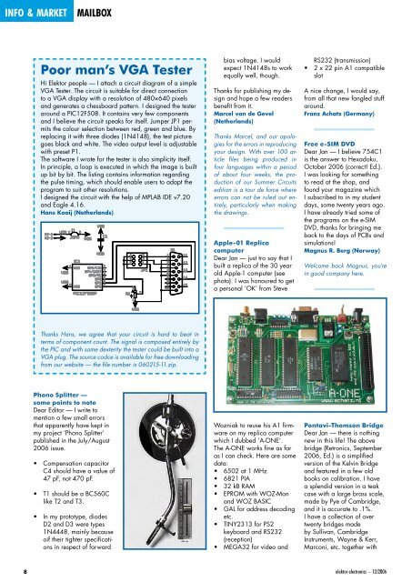
Dear Jan — just tro say <strong>that</strong> I<br />
built a replica <strong>of</strong> the 30 year<br />
old Apple-1 computer (see<br />
photo). I was honoured to get<br />
a personal ‘OK’ from Steve<br />
Wozniak to reuse his A1 firmware<br />
on my replica computer<br />
which I dubbed ‘A-ONE’.<br />
The A-ONE works fine as far<br />
as I can check. Here are some<br />
data:<br />
• 6502 at 1 MHz<br />
• 6821 PIA<br />
• 32 kB RAM<br />
• EPROM with WOZ-Mon<br />
and WOZ BASIC<br />
• GAL for address decoding<br />
etc.<br />
• TINY2313 for PS2<br />
keyboard and RS232<br />
(reception)<br />
• MEGA32 for video and<br />
RS232 (transmission)<br />
• 2 x 22 pin A1 compatible<br />
slot<br />
A nice change, I would say,<br />
from all <strong>that</strong> new fangled stuff<br />
around.<br />
Franz Achatz (Germany)<br />
Free e-SIM DVD<br />
Dear Jan — I believe 754C1<br />
is the answer to Hexadoku,<br />
October 2006 (correct! Ed.).<br />
I was looking for something<br />
to read at the shop, and<br />
found your magazine which<br />
I subscribed to in my student<br />
days, some twenty years ago.<br />
I have already tried some <strong>of</strong><br />
the programs on the e-SIM<br />
DVD, thanks for bringing me<br />
back to the days <strong>of</strong> PCBs and<br />
simulations!<br />
Magnus R. Berg (Norway)<br />
Welcome back Magnus, you’re<br />
in good company here.<br />
Pontavi-Thomson Bridge<br />
Dear Jan — there is nothing<br />
new in this life! The above<br />
bridge (Retronics, September<br />
2006, Ed.) is a simplified<br />
version <strong>of</strong> the Kelvin Bridge<br />
and featured in a few old<br />
books on calibration. I have<br />
a splendid version in a teak<br />
case with a large brass scale,<br />
made by Pye <strong>of</strong> Cambridge,<br />
and it is accurate to .1%.<br />
I have a collection <strong>of</strong> over<br />
twenty bridges made<br />
by Sullivan, Cambridge<br />
Instruments, Wayne & Kerr,<br />
Marconi, etc. together with<br />
elektor electronics - 12/2006


