Six-Level Single-Leg Flying Capacitor Converter Voltage Balancing ...
Six-Level Single-Leg Flying Capacitor Converter Voltage Balancing ...
Six-Level Single-Leg Flying Capacitor Converter Voltage Balancing ...

You also want an ePaper? Increase the reach of your titles
YUMPU automatically turns print PDFs into web optimized ePapers that Google loves.
where<br />
t = ∆t<br />
;<br />
t<br />
1<br />
2<br />
.......... .......... .......... .......... .......... ......<br />
t<br />
t<br />
10<br />
11<br />
= T<br />
1<br />
= ∆t<br />
+ ∆t<br />
;<br />
1<br />
1<br />
6<br />
= ∆t<br />
+ ∆t<br />
+ ∆t<br />
+ ∆t<br />
+ ∆t<br />
+ 5∆t<br />
= T<br />
PWM<br />
2<br />
+ ∆t<br />
;<br />
1<br />
3<br />
.......... .......... .......... .......... .......... ........<br />
4<br />
5<br />
6<br />
PWM<br />
Example 1. Consider single-leg six-level FC converter:<br />
= 50V<br />
; R = 1Ohm<br />
; L = 0.<br />
5mH<br />
; C C = C = C =<br />
V DC<br />
T PWM<br />
= C = 400uF<br />
; = 560us<br />
( 1 . 8kHz<br />
).<br />
1 = 2 3 4<br />
;<br />
(10)<br />
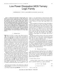
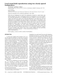
<strong>Converter</strong> dynamics switched simulation results obtained by<br />
programming formulas (9), (10) are presented in Fig.8.<br />
The average load current and capacitor voltages converge to<br />
i(<br />
∞)<br />
= V D /( 2R);<br />
v ( ∞)<br />
= V<br />
1<br />
v ( ∞)<br />
= 3V<br />
3<br />
DC<br />
DC<br />
/ 5;<br />
DC<br />
/ 5;<br />
v ( ∞)<br />
= 2V<br />
2<br />
v ( ∞)<br />
= 4V<br />
for any set of initial conditions.<br />
Current and <strong>Voltage</strong>s<br />
Current and <strong>Voltage</strong>s<br />
60<br />
50<br />
40<br />
30<br />
20<br />
10<br />
3<br />
DC<br />
DC<br />
/ 5;<br />
/ 5<br />
6-<strong>Level</strong> FC <strong>Converter</strong> Load Current and <strong>Capacitor</strong> <strong>Voltage</strong>s (D=0.1)<br />
(11)<br />
0<br />
0 0.05 0.1 0.15 0.2 0.25 0.3 0.35 0.4<br />
-10<br />
-20<br />
60<br />
50<br />
40<br />
30<br />
20<br />
10<br />
-10<br />
-20<br />
Load Current V1 <strong>Capacitor</strong> <strong>Voltage</strong> V2 <strong>Capacitor</strong> <strong>Voltage</strong> V3 <strong>Capacitor</strong> <strong>Voltage</strong> V4 <strong>Capacitor</strong> <strong>Voltage</strong><br />
Time, s<br />
a<br />
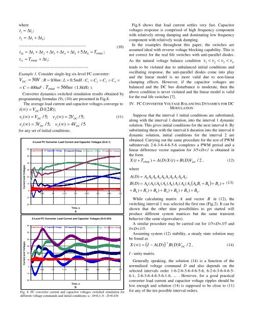
6-<strong>Level</strong> FC <strong>Converter</strong> Load Current and <strong>Capacitor</strong> <strong>Voltage</strong>s (D=0.434)<br />
Load Current V1 <strong>Capacitor</strong> <strong>Voltage</strong> V2 <strong>Capacitor</strong> <strong>Voltage</strong> V3 <strong>Capacitor</strong> <strong>Voltage</strong> V4 <strong>Capacitor</strong> <strong>Voltage</strong><br />
0<br />
0 0.05 0.1 0.15 0.2 0.25 0.3 0.35 0.4<br />
Time, s<br />
b<br />
Fig. 8. FC converter current and capacitor voltages switched simulation for<br />
different voltage commands and initial conditions: a - D=0.1; b - D=0.434<br />
Fig.8 shows that load current settles very fast. <strong>Capacitor</strong><br />
voltages response is comprised of high frequency component<br />
with relatively strong damping and dominating low frequency<br />
component with relatively weak damping.<br />
In the examples throughout this paper, the switches are<br />
assumed ideal with reverse voltage blocking capability. This is<br />
not correct for the real life switches with anti-parallel diodes.<br />
As the natural voltage balance condition v 1 < v2<br />
< v3<br />
< v4<br />
tends to be violated due to unbalanced initial conditions and<br />
oscillating response, the anti-parallel diodes come into play<br />
and the linear model is no more valid due to non-linear<br />
clamping effects. However, if the capacitor voltages are<br />
balanced and the DC bus disturbance is moderate, then the<br />
above condition is never violated and the linear model is valid<br />
for the real life switches [7].<br />
IV. FC CONVERTER VOLTAGE BALANCING DYNAMICS FOR DC<br />
MODULATION<br />
Suppose that the interval 1 initial conditions are substituted,<br />
along with the interval 1 duration, into the interval 1 dynamic<br />
solution. This gives initial conditions for the next interval 6. By<br />
substituting them with the interval 6 duration into the interval 6<br />
dynamic solution, initial conditions for the interval 2 are<br />
obtained. Carrying out the same procedure for the rest of PWM<br />
subintervals 2-6-3-6-4-6-5-6 completes a PWM period and a<br />
linear difference vector equation for 3/5