Six-Level Single-Leg Flying Capacitor Converter Voltage Balancing ...
Six-Level Single-Leg Flying Capacitor Converter Voltage Balancing ...
Six-Level Single-Leg Flying Capacitor Converter Voltage Balancing ...

Create successful ePaper yourself
Turn your PDF publications into a flip-book with our unique Google optimized e-Paper software.
for damping time constants (23), (25), (27) and non-zero DC<br />
bus voltage.<br />
To incorporate a non-zero DC bus voltage (forced solution)<br />
into (32), one has to add the balanced capacitor voltage values<br />
(1) and to replace the initial conditions according to<br />
v ( 0)<br />
→ v ( 0)<br />
−V<br />
/ 5;<br />
v ( 0)<br />
→ v ( 0)<br />
− 2V<br />
/ 5;<br />
v<br />
1<br />
3<br />
( 0)<br />
1<br />
→ v<br />
3<br />
DC<br />
( 0)<br />
− 3V<br />
DC<br />
/ 5;<br />
2<br />
v<br />
4<br />
( 0)<br />
2<br />
→ v<br />
4<br />
DC<br />
( 0)<br />
− 4V<br />
DC<br />
/ 5.<br />
(34)<br />
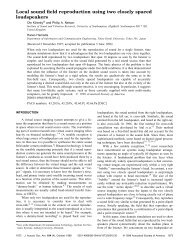
The final expressions are a little bit bulky and, therefore, are<br />
not presented here. Their comparison with accurate switched<br />
simulation results (Fig.10) shows good practical accuracy of<br />
approximate averaged voltage balancing dynamics solutions.<br />
Due to the carrier signals order C1; C2; C3; C4; C5 phaseshifted<br />
PWM strategy (Fig.2, 4, 6) may be referred to as "lead"<br />
one. Alternatively, PWM with reverse order C5; C4; C3; C2;<br />
C1 may be considered as "lag" strategy.<br />
As may be easily observed, the lag PWM strategy generates<br />
inverse switching states order with respect to the lead one. Lag<br />
PWM voltage balancing dynamics solution may be formally<br />
obtained from that for lead modulation by changing to the<br />
opposite the signs of sinusoidal terms in (33) [10, 11].<br />
VI. FC CONVERTER VOLTAGE BALANCING DYNAMICS<br />
ANALYSIS FOR AC MODULATION<br />
For AC PWM, the FC dynamics models become linear timevariable.<br />
For three-, four-, and five-level single-leg converters<br />
voltage balancing dynamics solutions for AC PWM were<br />
obtained from those for DC PWM by averaging oscillation<br />
frequencies and inverse time constants on AC fundamental<br />
period [9-11]. An explanation may be that this is possible due<br />
to "scalar" type dependence of non-damped equations on D<br />
similar to (28), (29). In six-level FC converter case, the<br />
situation is more complicated because for 0