Six-Level Single-Leg Flying Capacitor Converter Voltage Balancing ...
Six-Level Single-Leg Flying Capacitor Converter Voltage Balancing ...
Six-Level Single-Leg Flying Capacitor Converter Voltage Balancing ...

You also want an ePaper? Increase the reach of your titles
YUMPU automatically turns print PDFs into web optimized ePapers that Google loves.
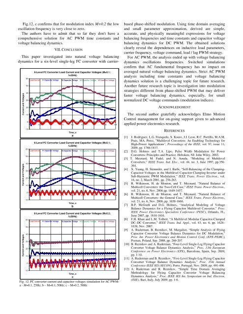
Fig.12, c confirms that for modulation index M=0.2 the low<br />
oscillation frequency is very close to zero.<br />
The authors have to admit that so far they don't have a<br />
comprehensive solution for AC PWM time constants and<br />
voltage balancing dynamics.<br />
VII. CONCLUSION<br />
This paper investigated into natural voltage balancing<br />
dynamics for a six-level single-leg FC converter with carrier-<br />
Current and <strong>Voltage</strong>s<br />
Current and <strong>Voltage</strong>s<br />
Current and <strong>Voltage</strong>s<br />
60<br />
50<br />
40<br />
30<br />
20<br />
10<br />
-10<br />
6-<strong>Level</strong> FC <strong>Converter</strong> Load Current and <strong>Capacitor</strong> <strong>Voltage</strong>s (M=0.1;<br />
f=25Hz)<br />
0<br />
0 0.05 0.1 0.15 0.2 0.25 0.3 0.35 0.4<br />
60<br />
50<br />
40<br />
30<br />
20<br />
10<br />
-10<br />
Load Current V1 <strong>Capacitor</strong> <strong>Voltage</strong> V2 <strong>Capacitor</strong> <strong>Voltage</strong> V3 <strong>Capacitor</strong> <strong>Voltage</strong> V4 <strong>Capacitor</strong> <strong>Voltage</strong><br />
Time, s<br />
a<br />
6-<strong>Level</strong> FC <strong>Converter</strong> Load Current and <strong>Capacitor</strong> <strong>Voltage</strong>s (M=0.1;<br />
f=50Hz)<br />
0<br />
0 0.05 0.1 0.15 0.2 0.25 0.3 0.35 0.4<br />
60<br />
50<br />
40<br />
30<br />
20<br />
10<br />
-10<br />
Load Current V1 <strong>Capacitor</strong> <strong>Voltage</strong> V2 <strong>Capacitor</strong> <strong>Voltage</strong> V3 <strong>Capacitor</strong> <strong>Voltage</strong> V4 <strong>Capacitor</strong> <strong>Voltage</strong><br />
Time, s<br />
b<br />
6-<strong>Level</strong> FC <strong>Converter</strong> Load Current and <strong>Capacitor</strong> <strong>Voltage</strong>s (M=0.2;<br />
f=50Hz)<br />
Load Current V1 <strong>Capacitor</strong> <strong>Voltage</strong> V2 <strong>Capacitor</strong> <strong>Voltage</strong> V3 <strong>Capacitor</strong> <strong>Voltage</strong> V4 <strong>Capacitor</strong> <strong>Voltage</strong><br />
0<br />
0 0.05 0.1 0.15 0.2 0.25 0.3 0.35 0.4<br />
Time, s<br />
c<br />
Fig. 12. FC converter current and capacitor voltages simulation for AC PWM:<br />
a - M=0.1, 25Hz; b – M=0.1, 50Hz; c – M=0.2, 50Hz<br />
based phase-shifted modulation. Using time domain averaging<br />
and small parameter approximation, derived are simple,<br />
accurate, and physically meaningful expressions for voltage<br />
balancing frequencies and time constants and capacitor voltage<br />
balancing dynamics for DC PWM. The obtained solutions<br />
clearly reveal the dependences on inductive load parameters,<br />
carrier frequency, voltage command, lead / lag PWM strategy.<br />
For AC PWM, the analysis ended up with voltage balancing<br />
dynamics oscillations frequencies. Switched simulations<br />
confirm that AC fundamental frequency has no impact on<br />
averaged natural voltage balancing dynamics. Strict AC PWM<br />
analysis including time constants and voltage balancing<br />
dynamics solution is a challenging topic for future research.<br />
Another future research topic is investigation into modulation<br />
strategies different from phase-shifted PWM that may deliver<br />
faster voltage balancing dynamics, especially, for small<br />
normalized DC voltage commands (modulation indices).<br />
ACKNOWLEDGMENT<br />
The second author gratefully acknowledges Elmo Motion<br />
Control management for on-going support given to advanced<br />
applied power electronics research.<br />
REFERENCES<br />
[1] J. Rodriguez, L.G. Franquelo, S. Kouro, J.I. Leon, R.C. Portillo, M.A.M.<br />
Prats, MA. Perez, "Multilevel <strong>Converter</strong>s: An Enabling Technology for<br />
High-Power Applications", Proceedings of the IEEE, vol. 97, issue 11,<br />
2009, pp. 1786-1817.<br />
[2] D.G. Holmes and T.A. Lipo, Pulse Width Modulation for Power<br />
<strong>Converter</strong>s: Principles and Practice. Hoboken, NJ: John Wiley, 2003.<br />
[3] T. Meynard, M. Fadel, and N. Aouda, “Modeling of Multilevel<br />
<strong>Converter</strong>s,” IEEE Trans. Ind. Elec., vol. 44, no. 3, June 1997, pp.356-<br />
364.<br />
[4] X. Yuang, H. Stemmler, and I. Barbi, “Self-<strong>Balancing</strong> of the Clamping-<br />
<strong>Capacitor</strong>-<strong>Voltage</strong>s in the Multilevel <strong>Capacitor</strong>-Clamping-Inverter under<br />
Sub-Harmonic PWM Modulation,” IEEE Trans. Power Electron., vol.<br />
16, no. 2, March 2001, pp. 256-263.<br />
[5] R. Wilkinson, H. de Mouton, and T. Meynard, “Natural Balance of<br />
Multicell <strong>Converter</strong>s: the Two-Cell Case,” IEEE Trans. Power Electron.,<br />
vol. 21, no. 6, Nov. 2006 pp. 1649-1657.<br />
[6] R. Wilkinson, H. de Mouton, and T. Meynard, “Natural Balance of<br />
Multicell <strong>Converter</strong>s: the General Case,” IEEE Trans. Power Electron.,<br />
vol. 21, no. 6, Nov. 2006, pp. 1658-1666.<br />
[7] B.P. McGrath and D.G. Holmes, “Analytical Modeling of <strong>Voltage</strong><br />
Balance Dynamics for a <strong>Flying</strong> <strong>Capacitor</strong> Multilevel <strong>Converter</strong>,” Proc.<br />
IEEE Power Electronics Specialists Conference (PESC), Orlando, FL,<br />
June 2007, pp. 1810-1816.<br />
[8] F.H. Khan and L.M. Tolbert, “A Multilevel Modular <strong>Capacitor</strong>-Clamped<br />
DC–DC <strong>Converter</strong>,” IEEE Trans. Ind. Appl., vol. 43, no. 6, pp. 1628–<br />
1638, Nov. 2007.<br />
[9] A. Ruderman, B. Reznikov, M. Margaliot, “Simple Analysis of <strong>Flying</strong><br />
<strong>Capacitor</strong> <strong>Converter</strong> <strong>Voltage</strong> Balance Dynamics for DC Modulation,”<br />
Proc. Int. Power Electronics and Motion Control Conf. (EPE-PEMC),<br />
Poznan, Poland, Sep. 2008, pp. 260-207.<br />
[10] B. Reznikov and A. Ruderman, “Four-<strong>Level</strong> <strong>Single</strong>-<strong>Leg</strong> <strong>Flying</strong> <strong>Capacitor</strong><br />
<strong>Converter</strong> <strong>Voltage</strong> Balance Dynamics Analysis,” Proc. 13th European<br />
Conference on Power Electronics (EPE), Barcelona, Spain, Sep. 2009,<br />
pp. 1-10.<br />
[11] A. Ruderman and B. Reznikov, “Five-<strong>Level</strong> <strong>Single</strong>-<strong>Leg</strong> <strong>Flying</strong> <strong>Capacitor</strong><br />
<strong>Converter</strong> <strong>Voltage</strong> Balance Dynamics Analysis,” Proc. 35th Annual<br />
Conference IEEE IES (IECON), Porto, Portugal, Nov. 2009, pp. 491-496.<br />
[12] A. Ruderman and B. Reznikov, “Simple Time Domain Averaging<br />
Methodology for <strong>Flying</strong> <strong>Capacitor</strong> <strong>Converter</strong> <strong>Voltage</strong> <strong>Balancing</strong><br />
Dynamics Analysis,” Proc. IEEE IES Int. Symposium on Ind. Electron.<br />
(ISIE), Bari, Italy, July 2009, pp. 1-6.