TBOP - Vanguard Networks
TBOP - Vanguard Networks
TBOP - Vanguard Networks

You also want an ePaper? Increase the reach of your titles
YUMPU automatically turns print PDFs into web optimized ePapers that Google loves.
<strong>Vanguard</strong> Managed Solutions<br />
<strong>Vanguard</strong> Applications Ware<br />
Serial Feature Protocols<br />
Transparent Bit Oriented Protocol (<strong>TBOP</strong>)
Notice<br />
©2003 <strong>Vanguard</strong> Managed Solutions, LLC.<br />
575 West Street<br />
Mansfield, Massachusetts 02048<br />
(508) 261-4000<br />
All rights reserved<br />
Printed in U.S.A.<br />
Restricted Rights Notification for U.S. Government Users<br />
The software (including firmware) addressed in this manual is provided to the U.S.<br />
Government under agreement which grants the government the minimum “restricted rights”<br />
in the software, as defined in the Federal Acquisition Regulation (FAR) or the Defense<br />
Federal Acquisition Regulation Supplement (DFARS), whichever is applicable.<br />
If the software is procured for use by the Department of Defense, the following legend<br />
applies:<br />
Restricted Rights Legend<br />
Use, duplication, or disclosure by the Government<br />
is subject to restrictions as set forth in<br />
subparagraph (c)(1)(ii) of the<br />
Rights in Technical Data and Computer Software<br />
clause at DFARS 252.227-7013.<br />
If the software is procured for use by any U.S. Government entity other than the Department<br />
of Defense, the following notice applies:<br />
Notice<br />
Notwithstanding any other lease or license agreement that may pertain to,<br />
or accompany the delivery of, this computer software, the rights of the<br />
Government regarding its use, reproduction, and disclosure are as set forth<br />
in FAR 52.227-19(C).<br />
Unpublished - rights reserved under the copyright laws of the United States.
Proprietary Material<br />
Notice (continued)<br />
Information and software in this document are proprietary to <strong>Vanguard</strong> Managed Solutions,<br />
LLC (or its Suppliers) and without the express prior permission of an officer, may not be<br />
copied, reproduced, disclosed to others, published, or used, in whole or in part, for any<br />
purpose other than that for which it is being made available. Use of software described in this<br />
document is subject to the terms and conditions of the Software License Agreement.<br />
This document is for information purposes only and is subject to change without notice.<br />
Part No. T0102-04, Rev G<br />
Publication Code DS<br />
First Printing: November 1998<br />
Manual is current for Release 6.2 of <strong>Vanguard</strong> Applications Ware<br />
To comment on this manual, please send e-mail to LGEN031@vanguardms.com
Overview<br />
Transparent Bit Oriented Protocol<br />
Introduction This manual describes how to configure the <strong>TBOP</strong> option on <strong>Vanguard</strong> platforms. It<br />
contains basic instructions on configuring <strong>TBOP</strong> for your nodes, including<br />
information about features, limitations, configuration, and statistics.<br />
Alarms and<br />
Reports<br />
For details about the alarms and reports for the <strong>TBOP</strong> protocol, refer to the <strong>Vanguard</strong><br />
Applications Ware Alarms and Reports Manual (Part Number T0005).<br />
In This Manual Topic See Page<br />
About the Transparent Bit Oriented Protocol ............................................... 2<br />
Typical Applications ..................................................................................... 3<br />
<strong>TBOP</strong> Over X.25 ...................................................................................... 4<br />
<strong>TBOP</strong> Over Frame Relay ......................................................................... 5<br />
Constant Bit Rate Application ................................................................. 6<br />
Configuration ................................................................................................ 8<br />
Statistics ........................................................................................................ 15<br />
Transparent Bit Oriented Protocol 1
About the Transparent Bit Oriented Protocol<br />
About the Transparent Bit Oriented Protocol<br />
What Is <strong>TBOP</strong>? The Transparent Bit Oriented Protocol (<strong>TBOP</strong>) is a transmission protocol that<br />
complements the suite of access protocols such as SDLC and XDLC. These<br />
protocols offer flexibility for connectivity and efficient use of WAN bandwidth. In<br />
contrast to spoofed access protocols, <strong>TBOP</strong> has the flexibility to pass most BOP<br />
protocols. You can deploy <strong>TBOP</strong> on access ports and use it in most applications<br />
operating with BOP-based protocols.<br />
Features <strong>TBOP</strong> has these key features:<br />
• Port speeds up to 2048 Kbps, depending on port hardware<br />
• Access to Frame Relay networks via the SPFM module<br />
• Access to X.25 networks<br />
• Support of constant bit rate applications such as video<br />
• Maximum frame size of 16384 bytes<br />
• Pipelining of frames in receive direction<br />
Receive Pipelining eliminates the need to wait for a complete frame to be received<br />
by the <strong>TBOP</strong> port before it is forwarded to the remote <strong>TBOP</strong> port. With receive<br />
pipelining, the frame being received is broken up into pieces (packets) and<br />
forwarded to the remote <strong>TBOP</strong> port. The sizes of the <strong>TBOP</strong> packets are determined<br />
by the lesser of the user configurable “Receive Byte Count” and the packet size on<br />
the networking link that the call is routed through.<br />
Note<br />
Transmit Pipelining is not implemented on the <strong>TBOP</strong>. The remote <strong>TBOP</strong> buffers<br />
all the packets of a remote frame and does not start to send them out to the<br />
attached device until the complete frame is received.<br />
Limitations <strong>TBOP</strong> has these limitations:<br />
• BOP frames must be delimited with at least 1 flag or mark idle, and the frame<br />
must have a CRC-16 trailer.<br />
• Support of maximum frame size of 16384 bytes and receive pipelining is<br />
limited to the serial ports on <strong>Vanguard</strong> products and the 6500PLUS CPU card.<br />
• Constant Bit Rate support does not provide synchronized clocking end to<br />
end.<strong>TBOP</strong>’s receive queue size is configurable which allows the user to<br />
choose the worst case accumulated delay. Data loss occurs periodically, the<br />
application must be able to recover from this.<br />
• Statistical multiplexers that continuously transmit small frames may make<br />
<strong>TBOP</strong> difficult to implement. Statistical multiplexers transmit a high rate of<br />
frames per second, so the load on the CPU is objectionably high. (Some<br />
statistical multiplexers can be configured to reduce the transmission rate of<br />
these small frames, which are typically sent during idle periods.)<br />
2 Transparent Bit Oriented Protocol
Typical Applications<br />
Typical Applications<br />
Introduction This section contains descriptions and configuration examples for typical<br />
applications of <strong>TBOP</strong>:<br />
• <strong>TBOP</strong> Over X.25<br />
• <strong>TBOP</strong> Over Frame Relay<br />
• Constant Bit Rate Application<br />
Transparent Bit Oriented Protocol 3<br />
T0102-04, Revision G Release 6.2
Typical Applications<br />
<strong>TBOP</strong> Over X.25<br />
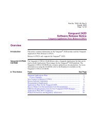
Description The configuration example shows how to use <strong>TBOP</strong> ports to connect over an X.25<br />
network. <strong>TBOP</strong> at node 100 originates the call to <strong>TBOP</strong> on node 200.<br />
Implementation<br />
Notes<br />
When you are connecting with <strong>TBOP</strong> over a switched network, such as X.25, the call<br />
may be initiated either automatically or when the DTE equipment connected to<br />
<strong>TBOP</strong> raises the EIA signal DTR.<br />
DTR maintains a network connection while this EIA signal is high. DTR-based<br />
calling is enabled when the Connection Type is set to either DTR, DTRD, or DTRP.<br />
You should use Autocalling to establish and maintain calls through the network. The<br />
autocalling parameters offer the flexibility to persist indefinitely to establish the<br />
connection or for a finite number of attempts. Autocalling is enabled when the<br />
Connection Type is set to SIMP. When the <strong>TBOP</strong> port exceeds the configurable<br />
number of autocall attempts, a port boot is required for the <strong>TBOP</strong> port to restart<br />
autocalling.<br />
Example Figure 1 shows how to configure the node to run <strong>TBOP</strong> over an X.25 connection:<br />
<strong>TBOP</strong> Port # 2<br />
HDLC<br />
Equipment<br />
<strong>TBOP</strong><br />
Node<br />
100<br />
Node Record<br />
Node Name <strong>TBOP</strong><br />
Node Address 100<br />
Node Number 100<br />
Port Record<br />
Port Number 2<br />
Port Type <strong>TBOP</strong><br />
Connection Type SIMP<br />
Clock Source INT<br />
Clock Speed 56000<br />
Autocall Mnemonic <strong>TBOP</strong><br />
Autocall Timeout (sec) 10<br />
Max # Autocall Attempts 0<br />
Port Number 1<br />
Port Type X25<br />
Connection Type SIMP<br />
Clock Source EXT<br />
Clock Speed 64000<br />
Link Address DTE<br />
Route Selection Table<br />
Address 200<br />
#1 Destination X25-1<br />
#1 Priority 1<br />
Mnemonic SelectionTable<br />
Mnemonic Name <strong>TBOP</strong><br />
Call Parameters 20002<br />
Figure 1. <strong>TBOP</strong> over X.25<br />
Port #1<br />
Node Record<br />
Node Name <strong>TBOP</strong><br />
Node Address 200<br />
Node Number 200<br />
Port Record<br />
Port Number 2<br />
Port Type <strong>TBOP</strong><br />
Connection Type SIMP<br />
Clock Source INT<br />
Clock Speed 56000<br />
Port Number 1<br />
Port Type X25<br />
Connection Type SIMP<br />
Clock Source EXT<br />
Clock Speed 64000<br />
Link Address DTE<br />
4 Transparent Bit Oriented Protocol<br />
X.25<br />
<strong>TBOP</strong><br />
Node<br />
200<br />
<strong>TBOP</strong> Port # 2<br />
HDLC<br />
Equipment
<strong>TBOP</strong> Over Frame Relay<br />
Typical Applications<br />
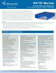
Description This configuration example illustrates how to use <strong>TBOP</strong> to connect over a Frame<br />
Relay connection.<br />
Implementation<br />
Notes<br />
When you connect <strong>TBOP</strong> over a Frame Relay network, the following points are<br />
relevant:<br />
• The autocall parameters are not meaningful (because Autocalling can only be<br />
deployed on a switched connection).<br />
• The Connection Type parameter should always be set to SIMP.<br />
• The Serial Protocol Forwarder Module (SPFM) is used to establish a static<br />
circuit from <strong>TBOP</strong> to a Frame Relay BYPASS station.<br />
Example Figure 2 shows how to configure the node to run <strong>TBOP</strong> over a Frame Relay<br />
connection:<br />
<strong>TBOP</strong> Port # 2<br />
HDLC<br />
Equipment<br />
<strong>TBOP</strong><br />
Node<br />
100<br />
Node Record<br />
Node Name <strong>TBOP</strong><br />
Node Address 100<br />
Node Number 100<br />
Port Record<br />
Port Number 1<br />
Port Type FRI<br />
Clock Source EXT<br />
Clock Speed 64000<br />
Control Protocol Support<br />
May Vary with Service Provider<br />
Port Number 2<br />
Port Type <strong>TBOP</strong><br />
Clock Source INT<br />
Clock Speed 56000<br />
FRI StationTable<br />
Station Type BYPASS<br />
DLCI 16<br />
SPFM Connection Table<br />
Serial Source Descr <strong>TBOP</strong>-2<br />
FRI Port Number 1<br />
FRI Station Number 1<br />
Figure 2. <strong>TBOP</strong> over Frame Relay<br />
Port #1<br />
Frame Relay<br />
Node Record<br />
Node Name <strong>TBOP</strong><br />
Node Address 200<br />
Node Number 200<br />
Port Record<br />
Port Number 1<br />
Port Type FRI<br />
Clock Source EXT<br />
Clock Speed 64000<br />
Control Protocol Support<br />
May Vary with Service Provider<br />
Port Number 2<br />
Port Type <strong>TBOP</strong><br />
Clock Source INT<br />
Clock Speed 56000<br />
Transparent Bit Oriented Protocol 5<br />
T0102-04, Revision G Release 6.2<br />
<strong>TBOP</strong><br />
Node<br />
200<br />
FRI StationTable<br />
Station Type BYPASS<br />
DLCI 16<br />
<strong>TBOP</strong> Port # 2<br />
HDLC<br />
Equipment<br />
SPFM Connection Table<br />
Serial Source Descr <strong>TBOP</strong>-2<br />
FRI Port Number 1<br />
FRI Station Number 1
Typical Applications<br />
Constant Bit Rate Application<br />
Description This section describes how to use <strong>TBOP</strong> in a Constant Bit Rate Application, such as<br />
Video. <strong>TBOP</strong>’s video support has been successfully tested with VTEL equipment,<br />
and it may be supported by other video equipment manufacturers that operate within<br />
the limitations stated earlier in this document.<br />
Constant Bit Rate The Constant Bit Rate (CBR) option allows HDLC frames to be transmitted and<br />
received with as few as one HDLC flag to delimit the frames. This table shows how<br />
<strong>TBOP</strong> controls the Transmission (Tx) Queue:<br />
Tx Queue Size You must select the Tx Queue Size based on the worst case delay that can be<br />
tolerated. Initially, the video session has a negligible delay. The <strong>TBOP</strong> port operating<br />
at the slower speed has an increasing delay during a video session until the<br />
transmission queue is filled to capacity, at which time it is purged. The video<br />
equipment re-synchronizes and the session proceeds with a negligible delay and<br />
continues this cycle indefinitely.<br />
Examples of TX<br />
Queue Size and<br />
Delay<br />
Without CBRWith CBR<br />
When <strong>TBOP</strong> detects its Transmission<br />
Queue is congested, <strong>TBOP</strong> notifies the<br />
network that it is congested before this<br />
queue overflows. In a Frame Relay<br />
network, <strong>TBOP</strong>’s congestion results in a<br />
Backward Explicit Congestion<br />
Notification (BECN) signalled towards<br />
the network.<br />
In the event that the transmission queue<br />
is filled to capacity, additional <strong>TBOP</strong><br />
frames received from the network would<br />
be discarded as they arrive.<br />
<strong>TBOP</strong> does not signal that it is<br />
congested because the source of the<br />
traffic always transmits at a constant<br />
rate. <strong>TBOP</strong> never notifies the network<br />
that it is congested (that is, a BECN is<br />
never sent).<br />
Once the transmission queue is filled to<br />
capacity, it is completely purged. The<br />
Transmission Queue becomes congested<br />
on the <strong>TBOP</strong> port with a slower clock.<br />
This table provides some values for Tx Queue Size based on VTEL’s HDLC frame.<br />
The VTEL HDLC frame (259 bytes) consists of the following components: 256<br />
bytes video + 2 byte CRC + 1 HDLC flag.<br />
Tx Queue Size<br />
Values<br />
1/4 sec<br />
delay<br />
1/2 sec<br />
delay<br />
3/4 sec<br />
delay<br />
256 Kbps 31 62 93 124<br />
384 Kbps 46 93 139 185<br />
512 Kbps 62 124 185 247<br />
1 sec<br />
delay<br />
6 Transparent Bit Oriented Protocol
Typical Applications<br />
Figure 3 shows a formula that you can use to calculate Tx Queue Size for any<br />
constant bit rate application:<br />
TxQueueSize WorstCaseDelay <strong>TBOP</strong>LinkSpeed<br />
1<br />
=<br />
× ------------------------------------------- × -------------------------------------------------------<br />
8bits video + CRC16 + flag<br />
Figure 3. Formula For Calculating Tx Queue Size<br />
Figure 4 shows a formula that you can use to calculate the resulting interval<br />
(in seconds) between purges of the transmission queue:<br />
TxQueueSize × ( video CRC16 flag)<br />
PurgeInterval = ---------------------------------------------------------------------------------------------------------------<br />
⎛Faster<strong>TBOP</strong>speed Ð Slower<strong>TBOP</strong>speed<br />
---------------------------------------------------------------------------------------------------------- ⎞<br />
⎝ 8bits<br />
⎠<br />
Figure 4. Formula For Calculating Interval Between Queue Purges<br />
Note<br />
The slow rate of purging the transmission queue coupled with VTEL’s expedient<br />
re-synchronization has a negligible effect on the video session.<br />
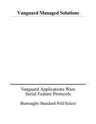
Example Figure 5 shows how to configure the node to run <strong>TBOP</strong> using the CBR option:<br />
<strong>TBOP</strong> Port # 2<br />
VTEL<br />
Equipment<br />
<strong>TBOP</strong><br />
Node<br />
100<br />
Node Record<br />
Node Name <strong>TBOP</strong><br />
Node Address 100<br />
Node Number 100<br />
Port Record<br />
Port Number 1<br />
Port Type FRI<br />
Clock Source EXT<br />
Clock Speed 1536000<br />
Control Protocol Support<br />
May Vary with Service Provider<br />
Port Number 2<br />
Port Type <strong>TBOP</strong><br />
Clock Source INT<br />
Clock Speed 384000<br />
Tx Queue Size 32<br />
Port Options CBR<br />
FRI StationTable<br />
Station Type BYPASS<br />
DLCI 16<br />
Congestion Control Disabled<br />
Max Inbound Queue 0<br />
SPFM Connection Table<br />
Serial Source Descr <strong>TBOP</strong>-2<br />
FRI Port Number 1<br />
FRI Station Number 1<br />
Figure 5. <strong>TBOP</strong> With CBR Option<br />
+ +<br />
Port #1<br />
Frame Relay<br />
Node Record<br />
Node Name <strong>TBOP</strong><br />
Node Address 200<br />
Node Number 200<br />
Port Record<br />
Port Number 1<br />
Port Type FRI<br />
Clock Source EXT<br />
Clock Speed 1536000<br />
Control Protocol Support<br />
May Vary with Service Provider<br />
Port Number 2<br />
Port Type <strong>TBOP</strong><br />
Clock Source INT<br />
Clock Speed 384000<br />
Tx Queue Size 32<br />
Port Options CBR<br />
FRI StationTable<br />
Station Type BYPASS<br />
DLCI 16<br />
Congestion Control Disabled<br />
Max Inbound Queue 0<br />
SPFM Connection Table<br />
Serial Source Descr <strong>TBOP</strong>-2<br />
FRI Port Number 1<br />
FRI Station Number 1<br />
Transparent Bit Oriented Protocol 7<br />
T0102-04, Revision G Release 6.2<br />
<strong>TBOP</strong><br />
Node<br />
200<br />
<strong>TBOP</strong> Port # 2<br />
VTEL<br />
Equipment
Configuration<br />
Configuration<br />
Introduction This section explains how to configure parameters for a <strong>TBOP</strong> port.<br />
Configuring a<br />
<strong>TBOP</strong> Port<br />
Figure 6 illustrates the <strong>TBOP</strong> port configuration parameters.<br />
Note<br />
For this configuration to take effect, you must boot the node. For information<br />
about booting the node, refer to the <strong>Vanguard</strong> Basic Configuration Manual<br />
(Part Number T0113).<br />
If you have enabled Ease of Configuration, you need to boot only the port to<br />
make changes to the parameters marked with an asterisk. For more information,<br />
refer to the Ease of Configuration section in the introductory portion of the<br />
binder (Serial Feature Protocols Manual, Part Number T0102).<br />
Node: Address: Date: Time:<br />
Menu: Configure Path:<br />
Node<br />
Port<br />
Null<br />
X25<br />
Port Name<br />
*Port Number<br />
PAD<br />
MUX<br />
Figure 6. Configure <strong>TBOP</strong> Port Record and Parameters<br />
8 Transparent Bit Oriented Protocol<br />
<strong>TBOP</strong><br />
Connection Type<br />
Clock Source<br />
Clock Speed<br />
Transmission Encoding<br />
Receive Byte Count<br />
Maximum Frame Size<br />
Port Option<br />
EIA Signalling Action<br />
RTS/CTS Delay<br />
DCD to Data Timer Duration<br />
Autocall Mnemonic<br />
Autocall Timeout<br />
Maximum Number of Autocall Attempts<br />
Port Subaddress<br />
CUG Membership<br />
Billing Records<br />
Number of Idle Flags
Configuration<br />
Transparent CCS When Transparent CCS, which uses <strong>TBOP</strong>, is operating, only these parameters<br />
appear:<br />
• Tx Queue Size<br />
• EIA Signalling Action<br />
• Autocall Mnemonic<br />
• Autocall Timeout<br />
• Maximum Number of Autocall Attempts<br />
• Port Subaddress<br />
• CUG Membership<br />
• Billing Records<br />
The other parameters do not appear because they do not apply when <strong>TBOP</strong> is<br />
operating over a physical T1/E1 port. For more information about Transparent CCS,<br />
refer to the Voice Option manuals in the <strong>Vanguard</strong> Multimedia Feature Protocols<br />
Manual (Part Number T0104).<br />
Configuring a<br />
Virtual Port<br />
If you are configuring a virtual port, only the following parameters appear in a <strong>TBOP</strong><br />
record:<br />
• Autocall Mnemonic<br />
• Autocall Timeout<br />
• Maximum Number of Autocall Attempts<br />
• Port Subaddress<br />
• CUG Membership<br />
• Billing Records.<br />
Others parameters relevant to physical operation of a port are not listed in a virtual<br />
port record.<br />
Transparent Bit Oriented Protocol 9<br />
T0102-04, Revision G Release 6.2
Configuration<br />
<strong>TBOP</strong> Parameters These are the <strong>TBOP</strong> port configuration parameters:<br />
Connection Type<br />
Range SIMP, DTR, DTRD, DTRP<br />
Default SIMP<br />
Description Specifies the type of control signal handshaking required before<br />
logical connections can be made to this port.<br />
• SIMP (Simple): Select this when the terminals are wired to<br />
the port with a cable that has a minimum of conductors so that<br />
no control signals are used. Such cabling provides only<br />
ground, transmit and receive data, transmit and receive clock.<br />
Control signals from the port are maintained high.<br />
• DTR: Use this when the device connected to the port provides<br />
DTR to maintain the EIA connection.<br />
• DTRD: DTR signal required. DCD, DSR, CTS drop for one<br />
second between calls. During the control signal drop, the port<br />
is unable to receive calls.<br />
• DTRP: Use this in applications where DTR is passed end to<br />
end.<br />
Clock Source<br />
Range EXT, INT<br />
Default EXT<br />
Description Specifies the source of clocking:<br />
• INT: Port provides clocking<br />
• EXT: External device provides clocking signals.<br />
When set to EXT, the port's clock speed is determined by an<br />
external device, and the clock speed must be set to the external<br />
clock’s speed.<br />
Clock Speed<br />
Range 1200 to 2048000<br />
Default 9600<br />
Description Specifies the speed of the port in bits per second. This parameter<br />
must be set to the external device's clock speed when the<br />
parameter Clock Source=EXT.<br />
10 Transparent Bit Oriented Protocol
Configuration<br />
Transmission Encoding<br />
Range NRZ, NRZI<br />
Default NRZ<br />
Description Specifies the type of transmission coding used on this <strong>TBOP</strong> link.<br />
• NRZ: Non-Return to Zero<br />
• NRZI: Non-Return to Zero Inverted<br />
Receive Byte Count<br />
Range 128, 256, 384, 512, 640, 768, 896, MAX (1024)<br />
Default MAX<br />
Description Specifies the number of bytes that are collected before data is<br />
forwarded to the network. This parameter can be used to decrease<br />
the network delay by controlling the rate of pipelining.<br />
Maximum Frame Size<br />
Range 1036 - 16384<br />
Default 4500<br />
Description Specifies the maximum allowable frame size (in bytes).<br />
Tx Queue Size<br />
Range 16-800<br />
Default 32<br />
Description Specifies the size of the transmission queue. When the<br />
transmission queue is full, it purges all the frames in it. You must<br />
select the Tx Queue Size based on the worst case delay that can be<br />
tolerated.<br />
Note<br />
Perform a Node boot for changes to this parameter to take effect.<br />
Transparent Bit Oriented Protocol 11<br />
T0102-04, Revision G Release 6.2
Configuration<br />
Channelized T1/E1 Connectivity<br />
Range NO,YES<br />
Default NO<br />
Description Specifies if a frame check sequence is generated for transmitted<br />
frames and if the frame check sequence is stripped from received<br />
frames. Set to YES when connecting to a virtual <strong>TBOP</strong> port which<br />
maps to a T1 or E1 port.<br />
• YES: Generate FCS for transmitted frames and strip FCS<br />
from received frames.<br />
• NO: Don't generate FCS for transmitted frames or strip FCS<br />
from received frames.<br />
Port Option<br />
Range NONE, MARKi, CBR<br />
Default NONE<br />
Description Specifies the type of idle that is used between frames.<br />
• NONE: Port uses Flag idle between frame exchanges.<br />
• MARKi: Port uses Mark idle between frame exchanges.<br />
• CBR (Constant Bit Rate): Port uses a constant bit rate and,<br />
therefore, may not have flag idles between frame exchanges.<br />
Note<br />
If you select the MARKi option, set the Number of Idle Flags<br />
parameter to 2 or greater. The Number of Idle Flags parameter<br />
does not appear if you choose the CBR option.<br />
EIA Signalling Action<br />
Range NONE, SWITCH, CTS<br />
Default NONE<br />
Description Specifies the EIA signalling action that is allowed:<br />
• NONE: None<br />
• SWITCH: The <strong>Vanguard</strong> node raises DCD at the beginning of<br />
the frame and drops DCD when frame transmission is<br />
complete. The DCD is held high after transmitting the frame<br />
for the duration of three character times based on the<br />
configured clock speed.<br />
• CTS: The <strong>Vanguard</strong> node raises CTS when it receives an RTS<br />
signal.<br />
Note<br />
SWITCH+CTS: The operations can be combined by summing<br />
SWITCH and CTS.<br />
12 Transparent Bit Oriented Protocol
Configuration<br />
RTS/CTS Delay<br />
Range 2 to 200<br />
Default 2<br />
Description Specifies the length of time the device delays CTS after RTS is<br />
raised (when EIA Signalling Action = CTS).<br />
The delay is specified in 50 millisecond units (1 = 50 ms).<br />
DCD to Data Timer Duration<br />
Range 1 to 255<br />
Default 1<br />
Description Specifies the length of time (in milliseconds) that DCD is held<br />
high before data is forwarded to the attached device. This is used<br />
when EIA Signalling Action = SWITCH or SWITCH+CTS.<br />
Autocall Mnemonic<br />
Range 0 to 8 alphanumeric characters<br />
Default (blank)<br />
Description Specifies the mnemonic name used for autocalling.<br />
Autocall Timeout<br />
Range 5 to 255<br />
Default 10<br />
Description Specifies the time (in seconds) between call attempts when<br />
autocalling.<br />
Maximum Number of Autocall Attempts<br />
Range 0 to 255<br />
Default 0<br />
Description Specifies the number of times the <strong>TBOP</strong> port attempts to call. A<br />
value of zero allows unlimited attempts.<br />
Transparent Bit Oriented Protocol 13<br />
T0102-04, Revision G Release 6.2
Configuration<br />
Port Subaddress<br />
Range 0 to 3 decimal digits<br />
Default the number of this port<br />
Description Specifies the subaddress for this <strong>TBOP</strong> port.<br />
Incoming calls from the network with a network address<br />
consisting of the Node Address specified in the node record and<br />
this subaddress arrive at this <strong>TBOP</strong> port. When a <strong>TBOP</strong> port<br />
makes a call, the Node Address plus this subaddress is inserted<br />
into the calling address field.<br />
CUG Membership<br />
Range 0 to 8 two-digit numbers<br />
Default --,--,--,--,--,--,--,--<br />
Description Specifies membership to Closed User Groups (CUGs). A port may<br />
be a member of up to eight CUGs. Each CUG membership must<br />
be a two-digit number (00 to 99) separated from other groups by a<br />
comma. To indicate that the port is not a member of a CUG, press<br />
the space bar twice ( -- ).<br />
Billing Records<br />
Range Off, On<br />
Default Off<br />
Description Controls creation of billing records for this port.<br />
• On: Billing records are generated for all calls to and from this<br />
port and failed calls from this port.<br />
• Off: No billing records are generated.<br />
Number of Idle Flags<br />
Range 1 to 15<br />
Default 2<br />
Description Controls the number of idle flags placed between two <strong>TBOP</strong><br />
frames during transmission.<br />
Note<br />
If you enable the MARKi (Mark idle) port option, set the number<br />
of idle flags to 2 or greater. This parameter does not appear if you<br />
select the CBR option.<br />
14 Transparent Bit Oriented Protocol
Statistics<br />
Statistics<br />
Introduction This section describes the statistics used with <strong>TBOP</strong>. Other statistics are described in<br />
the <strong>Vanguard</strong> Basic Configuration Manual. You can use the information appearing<br />
on the following screen to monitor the operation of a <strong>TBOP</strong> port.<br />
Detailed <strong>TBOP</strong> Port<br />
Statistics<br />
Detailed <strong>TBOP</strong> Port<br />
Statistics Screens<br />
Detailed <strong>TBOP</strong> Port Statistics provide status reports about various operations of a<br />
<strong>TBOP</strong> port. To view the Detailed <strong>TBOP</strong> Port Statistics perform these steps:<br />
Step Action<br />
1 Select Status/Statistics from the CTP Main menu.<br />
2 Select Detailed Port Statistics from the Status/Statistics menu<br />
3 At the prompt, enter the number of the selected port.<br />
The information displayed is similar to that shown in Figure 7 and Figure 8.<br />
You can acquire statistics for any active <strong>TBOP</strong> port as you do for any other port.<br />
The fields appear on the screen to reflect the status of the <strong>TBOP</strong> port<br />
(see Figures 7 and 8).<br />
Node: Address: Date: Time:<br />
Detailed <strong>TBOP</strong> Port Statistics: Port 3 Page: 1 of 2<br />
Port Number: 3 Port Type: <strong>TBOP</strong><br />
Port Status: Up Port Speed: 9610<br />
Physical Summary:<br />
Overrun: 0 Underrun: 0 CRC: 2927 Non-Octet Aligned: 58411<br />
Data Summary:<br />
IN OUT IN OUT<br />
Characters: 37237278 42548484 Characters/sec: 635 728<br />
Frames: 365073 417605 Frames /sec: 6 7<br />
Lost Segments: 0 0<br />
Frames Queued: 0 1 Utilization: 53% 61%<br />
Queue Capacit: 100 16<br />
Interface Summary: EIA-232-D DCE INPUT OUTPUT<br />
DTR RTS MB P14 DSR DCD RI CTS<br />
State: Connected (SIMPLE) H H L L H H L H<br />
Press any key to continue ( ESC to exit ) ...<br />
Figure 7. Detailed <strong>TBOP</strong> Port Statistics Screen - Page 1<br />
Transparent Bit Oriented Protocol 15<br />
T0102-04, Revision G Release 6.2
Statistics<br />
<strong>TBOP</strong> Port<br />
Statistics Terms<br />
Node: Address: Date: Time:<br />
Detailed <strong>TBOP</strong> Port Statistics:Port 3 Page: 2 of 2<br />
Call Summary:<br />
Current Status: Connected<br />
Time until next auto-call attempt: 0 secs<br />
Number of auto-call attempts: 0<br />
Last clear cause code: 0 (Cleared by other end)<br />
Last clear diagnostic code: 0 (No more information)<br />
Last Inbound Call:<br />
Called Address: 20003<br />
Calling Address: 10003<br />
CUD:<br />
Last Outbound Call:<br />
Called Address:<br />
Calling Address:<br />
CUD:<br />
Figure 8. Detailed <strong>TBOP</strong> Port Statistics Screen - Page 2<br />
This table explains the terms found in the <strong>TBOP</strong> Port Statistics screens:<br />
Term Description<br />
Port Number Specifies a specific port in the node.<br />
Port Type Indicates the type of port.<br />
Port Status Specifies the current port status.<br />
• Up: Port is enabled by the CTP.<br />
• Disabled: Port is disabled by the CTP.<br />
• Busy Out: The port is busied out by the CTP.<br />
• Down: Port is not enabled, disabled, or busied out by the<br />
CTP.<br />
Port Speed Message transmission speed in bits per second.<br />
Physical Summary Overrun Errors: Total number of overrun errors counted by<br />
the I/O driver.<br />
• Underrun Errors: Total number of underrun errors<br />
counted by the I/O driver.<br />
• CRC Errors: Total number of CRC errors counted by the<br />
I/O driver.<br />
16 Transparent Bit Oriented Protocol
Term Description<br />
Statistics<br />
Data Summary Characters In/Out: Number of characters received or<br />
transmitted since last boot or statistics reset. Header<br />
characters are not included.<br />
• Frames In/Out: Number of SDLC frames received or<br />
transmitted since last boot or statistics reset.<br />
• Characters/sec In/Out: The average number of characters<br />
received or transmitted per second.<br />
• Frames/sec In/Out: The average number of messages<br />
received or transmitted per second.<br />
• Lost Frames: The number of discarded inbound and<br />
outbound segments. This statistic can indicate:<br />
– The node is becoming congested.<br />
– The inbound node is congested.<br />
– The received segment cannot be queued in the inbound<br />
queue.<br />
– The received segments size is greater that the<br />
configured frame size.<br />
– The node received out of sequence segments from the<br />
network.<br />
– The outbound queue holding the segments received<br />
from the network is full.<br />
• Frames Queued: Number of outstanding queued<br />
segments in the inbound and outbound queues.<br />
• Utilization: Displays the inbound and outbound use of<br />
the port expressed as the ratio of bytes per second / port<br />
speed in bytes.<br />
– For example: if the inbound bytes/second rate is 600<br />
and the port speed is 9600 baud, then the inbound<br />
utilization is 600(9600/8) = 600/1200*100 = 50%.<br />
• Queue Capacity:<br />
– In: Maximum number of <strong>TBOP</strong> frames in the inbound<br />
queue that can be stored without discarding frames.<br />
These frames are in the queue. When the network is<br />
congested, they are sent later.<br />
– Out: Maximum number of <strong>TBOP</strong> frames that can be<br />
stored in the outbound queue. These recombined<br />
frames are held in the order that they are originally<br />
received by the remote <strong>TBOP</strong>.<br />
Note<br />
IN and OUT are used with reference to the interface at the<br />
<strong>TBOP</strong> port.<br />
Summary • INPUT/OUTPUT: Summary of the current status of EIA<br />
control leads.<br />
• State: The EIA state of the port.<br />
Transparent Bit Oriented Protocol 17<br />
T0102-04, Revision G Release 6.2
Statistics<br />
Term Description<br />
Call Summary • Current Status: Status of the call on the specific port.<br />
– Connected: Call between <strong>TBOP</strong> ports is established.<br />
– Called: <strong>TBOP</strong> port is autocalled by another <strong>TBOP</strong> port<br />
and is waiting for the EIA connection to be<br />
established.<br />
– Disconnected: No calls in progress.<br />
• Time Until Next Auto-Call Attempt: Time until the next<br />
autocall attempt.<br />
• Number of Auto-Call Attempts: Number of autocalls to<br />
be attempted.<br />
• Last Clear Cause Code: Last clear cause code received by<br />
the port.<br />
• Last Clear Diagnostics Code: Last clear diagnostic code<br />
received by the port.<br />
Last Inbound Call Called Address/Calling Address/CUG: Report on called and<br />
calling addresses and CUG of the last outbound call.<br />
Last Outbound Call Called Address/Calling Address/CUG: Report on called and<br />
calling addresses and CUG of the last outbound call.<br />
18 Transparent Bit Oriented Protocol
A<br />
Alarms 1<br />
Autocalling 4<br />
C<br />
CCS Protocol 9<br />
Configuration Options<br />
listed by configuration menu 8<br />
Configuring<br />
port parameters 8<br />
Constant Bit Rate 6<br />
D<br />
Detailed Port Statistics<br />
description 15<br />
screens 15<br />
viewing 15<br />
F<br />
Frame Relay 5<br />
L<br />
Limitations 2<br />
M<br />
Monitoring<br />
operation 15<br />
status reports 15<br />
P<br />
Port Configuration Parameters<br />
clock speed 10<br />
connection type 10<br />
DCD to data timer duration 13<br />
Purges 7<br />
R<br />
Receive Pipelining<br />
function 2<br />
Reports 1<br />
S (Continued)<br />
Screens. See Detailed Port Statistics<br />
Statistics<br />
acquiring for an active port 15<br />
description 15<br />
detailed <strong>TBOP</strong> port 15<br />
switched network, 4<br />
T<br />
<strong>TBOP</strong><br />
definition 2<br />
limitations 1, 2<br />
TCOP<br />
Alarms and reports 1<br />
Transparent Bit Oriented Protocol, see <strong>TBOP</strong><br />
Tx Queue Size 6, 11<br />
W<br />
Worksheet<br />
for sample application 18<br />
Index<br />
Index-1