Special Edition, September 2012 - Land Transport Authority
Special Edition, September 2012 - Land Transport Authority
Special Edition, September 2012 - Land Transport Authority

Create successful ePaper yourself
Turn your PDF publications into a flip-book with our unique Google optimized e-Paper software.
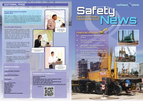
EDITORIAL PAGE<br />
Annual Safety Award Convention<br />
(ASAC) <strong>2012</strong><br />
ASAC gives recognition to LTA’s contractors who have been most<br />
proactive and successful in safety, health and environment efforts. In<br />
addition to the prestigious awards that will be presented, this year’s<br />
event will feature the launch of the Zero Accident movement and the<br />
Construction Safety Guidebook. Do keep a lookout for the highlights of<br />
the event in the next issue of Safety News.<br />
LTA 27th Safety Workshop<br />
The 27th Safety Workshop organised by Safety<br />
Division was held on 16th May <strong>2012</strong> at the HSO<br />
Auditorium. It was attended by more than 100<br />
officers from Rail, Road Projects and Engineering<br />
Groups. The forum served as an excellent<br />
platform for project teams to share the safety<br />
challenges they faced and how they were<br />
overcome. Topics presented were:<br />
1. Changes in Earth Control Measures (ECM)<br />
Requirements and Case Studies on LTA<br />
Construction Sites by Mr Goh Wee Kiat<br />
from Catchment & Waterways Department,<br />
Public Utilities Board (PUB).<br />
2. Bukit Timah Canal Localized Diversion –<br />
Installation of 2.6m Diameter Twin Steel Pipes<br />
(C916) by Executive Project Engineer<br />
Michael Tom<br />
3. Half-Height Platform Screen Doors (HHPSD)<br />
Installation At Existing 36 Elevated Stations<br />
(C1320) by Principal Engineering Officer<br />
Teo Kim Yon<br />
Editorial Committee<br />
Advisor<br />
Corporate Safety Committee<br />
Editor<br />
Zarith Sofia Ahmad Magad<br />
Circulation Officer<br />
Zhuo Shumei<br />
Writers<br />
Alvin Kok Chun Chiat<br />
Randolph Jung<br />
Alicia Tan Yee Jun<br />
Adrian Cheong<br />
Ernest Poon<br />
Sihan Sadikin<br />
Yeu Eng Hock<br />
Silvia Halim<br />
Mohamed Rozmand bin Jamaludin<br />
Executive Project Engineer<br />
Michael Tom<br />
Contributions or Feedback to:<br />
<strong>Land</strong> <strong>Transport</strong> <strong>Authority</strong><br />
Safety Division<br />
No.1 Hampshire Road, Blk 5, Level 4, Singapore 219428<br />
Tel: (65) 6299 6476 Fax: (65) 6396 1188<br />
Email address: zarith_sofia_ahmad_magad@lta.gov.sg<br />
Safety News is also available online at<br />
http://www.lta.gov.sg/content/lta/en/projects/safety_first_.html<br />
or scan<br />
Guest Speaker<br />
Mr Goh Wee Kiat<br />
from PUB<br />
Principal<br />
Engineering Officer<br />
Teo Kim Yon<br />
Safety<br />
Safe Use of Heavy<br />
Machinery at Work<br />
Featured Articles<br />
02 Safe Use of Heavy Machinery<br />
at Work<br />
04 Prevention of Compressed Air Illness<br />
and Barotrauma<br />
06 Work Safety with Heavy Machinery<br />
for CTE Widening Project<br />
08 Learning from Japan, Hongkong and<br />
South Korea on Means of Construction<br />
Noise Control<br />
10 Fire and Life Safety In Woodsville Tunnel<br />
12 Importance of Good Sight Visibility<br />
Along Roads<br />
News<br />
SPECIAL EDITION / ISSN 1793-1665 SEP <strong>2012</strong>
SAFETY NEWS<br />
SAFE USE OF HEAVY MACHINERY AT WORK<br />
S<br />
Introduction<br />
With the increase in both infrastructure and building construction<br />
in recent years, many kinds of heavy machinery have been<br />
developed to increase the efficiency and safety of construction<br />
work. Such heavy machinery used on construction sites<br />
typically consist of bored piling rigs, cranes and excavators.<br />
The use of heavy machinery, while increasing the efficiency of<br />
construction work, carries the inherent risk of causing serious<br />
injuries and property damage if it is involved in an accident.<br />
This article aims to identify common causes of accidents<br />
related to heavy machinery and how the associated risks can<br />
be minimized or eliminated through the use of the 3Ms (Man,<br />
Machinery and Methods) approach.<br />
Causes of Heavy Machinery Accidents<br />
There are numerous and various causes of machinery related<br />
accidents that can be broadly categorized into:<br />
Planning & Supervision<br />
• Insufficient procedures / resources<br />
• Failure to adhere to procedures<br />
• Lack of supervision<br />
Equipment<br />
• Lack of maintenance regime<br />
• Faulty / illegally modified components<br />
Human Factor<br />
• Negligence<br />
• Inexperience<br />
• Complacency<br />
• Poor communication<br />
Hence, using the 3Ms approach to manage and mitigate these<br />
risks would ensure that working with heavy machinery would<br />
be made much safer.<br />
Man<br />
AFE USE OF HEAVY MACHINERY AT WORK<br />
Training<br />
All personnel involved in the operation of heavy machinery must<br />
attend and pass the relevant training courses. Besides passing<br />
the prescribed courses, it is also important to ensure that the<br />
personnel are always reminded of the potential hazards that<br />
the machinery they are operating can pose.<br />
Competent / Appointed<br />
The relevant personnel associated with the heavy machinery<br />
must be deemed competent and formally appointed prior to<br />
operation of the machines.<br />
Figure 1: Appointed<br />
competent banksman<br />
Figure 2: Appointed<br />
lifting team<br />
Planning<br />
Comprehensive planning and coordination among the various<br />
construction teams are essential to ensure that all parties<br />
involved in the use of the heavy machinery or working nearby<br />
are well aware of the hazards and the measures that can be<br />
implemented to mitigate these hazards.<br />
Supervision<br />
During the operation of heavy machinery, close supervision<br />
must be conducted to ensure that the work is carried out in a<br />
safe manner and within a safe environment. <strong>Special</strong> attention<br />
and supervision has to be dedicated to heavy machinery<br />
operations that are carried out late in the night and during<br />
early morning where fatigue may set in, resulting in loss of<br />
concentration. We must also step up supervision during<br />
weekends and public holidays when project management staff<br />
tend to be fewer.<br />
Machinery<br />
Figure 3: Planning and coordination meetings<br />
Figure 4: All lifting works are<br />
closely supervised<br />
Figure 5: Supervision of bored<br />
piling operation<br />
Examination<br />
Heavy machinery such as cranes and bored piling rigs which<br />
involve lifting operations have to be examined, load tested and<br />
certified by an Authorised Examiner prior to usage on site.<br />
For excavators, it must be examined and certified by the<br />
supplier’s mechanic before commencement of work.<br />
Maintenance Regime<br />
All machinery will have to undergo monthly maintenance by<br />
the Crane Maintenance Supervisor or the main contractor’s<br />
mechanic. All records of the maintenance are to be kept for<br />
verification purposes.<br />
Crane, excavator and bored pile rig operators are also required<br />
to perform daily pre-operation checks on the machinery that<br />
they are operating.<br />
2 3<br />
Methods<br />
Classification Frequency of Certification<br />
Lifting Machine 6 months<br />
Classification Frequency of Maintenance<br />
All Machinery 1 month<br />
Source: LTA General Specification<br />
Figure 6: Inspection: over-derricking limit switch<br />
Figure 7: Excavator operator conducting pre-operation checks<br />
Use of heavy machinery should be properly planned and safe<br />
procedures should be developed before the actual operation.<br />
Risk assessment<br />
Detailed risk assessment must be carried out before heavy<br />
machinery operations as it identifies the associated safety and<br />
health hazards and the level of risks involved. Measures to<br />
reduce the risks identified must also be implemented.<br />
Safe Work Procedure<br />
Safe work procedure must be developed and cascaded to all<br />
personnel involved for the purpose of carrying out work safely.<br />
Permit-to-Work<br />
Permit-to-Work (PTW) is a system to manage and control<br />
hazardous work and shall be implemented for heavy machinery<br />
operations. The contractor’s supervisor coordinating the heavy<br />
machinery operation is to apply for the PTW to carry out the<br />
operation. In the application for PTW, he should state the scope<br />
and conditions in which the operation is to be carried out. An<br />
independent inspection by an assessor is then conducted<br />
on-site to verify that appropriate control measures have been<br />
taken to mitigate any foreseeable risks. After confirming that<br />
the measures have been implemented, the application would<br />
then be approved by an authorized person (typically the project<br />
manager).<br />
Control of work area<br />
Access to the working area should be restricted to those who<br />
are involved in the work. The work area should be cordoned off,<br />
warning signs are to be displayed and steel plates are to be<br />
provided at the base of machines for firm footing.<br />
Conclusion<br />
Figure 9:<br />
Work area cordoned off<br />
Figure 8: Conducting risk assessment<br />
Figure 10:<br />
Demarcated work area<br />
As all heavy machinery related operations have an inherent<br />
degree of risk, proper risk management is important to identify<br />
the potential hazards and address them. These risks can<br />
be significantly minimized or eliminated through the 3Ms<br />
approach.<br />
It is of paramount importance to ensure all heavy machinery<br />
operations on LTA sites are carried out safely. With close<br />
collaboration between our project teams and contractors, we<br />
can achieve this goal.<br />
Kok Chun Chiat Alvin<br />
Deputy Safety & Health Manager<br />
Safety Division<br />
SAFE USE OF HEAVY MACHINERY AT WORK<br />
SAFETY NEWS
SAFETY NEWS<br />
PREVENTION OF COMPRESSED AIR ILLNESS AND BAROTRAUMA<br />
PREVENTION OF COMPRESSEd AIR IllNESS ANd BAROTRAUMA<br />
Introduction<br />
Tunnel boring machines (TBM), also fondly known as “moles”,<br />
are machines used to excavate circular tunnels through various<br />
types of soil conditions. They are ideal for use in heavily<br />
urbanised Singapore for the construction of our underground<br />
rail network as it has the advantage of causing minimal<br />
disturbance to the surrounding ground and its ability to tunnel<br />
deep beneath the ground surface.<br />
LTA tunnelling works can reach depths of 57 meters. At such<br />
depths, compressed air must applied at the cutter-head<br />
chamber of the TBM (area behind the cutter-head) to stabilize<br />
the tunnel face against soil collapse so that site personnel can<br />
enter safely to carry out works such as inspection, change of<br />
cutting tools, removing of underground obstruction etc.<br />
Entry & Exit From Compressed Air Environment<br />
In order for personnel to transit safely from a free-air environment<br />
to a compressed air environment, a chamber within the TBM,<br />
called the man-lock is used.<br />
Man-lock<br />
Figure 1: Tunnel Boring Machine<br />
Figure 2: Man-lock located in a TBM<br />
Personnel working in a compressed air environment must first<br />
enter the man-lock where air pressure is gradually raised to the<br />
desired level (compression) for them to carry out work in the<br />
cutter-head chamber. After the work is completed, they will<br />
have to return to the man-lock to decompress allowing their<br />
bodies to normalise to the free-air atmospheric pressure.<br />
Personnel who enter and/or work in a compressed air<br />
environment are exposed to health hazards such as<br />
decompression sickness and barotrauma if the process is not<br />
well managed.<br />
Decompression Sickness & Barotrauma<br />
Decompression Sickness<br />
At normal atmospheric pressure, the body tissues and blood<br />
are fully saturated with air. When the body is subjected to<br />
increased air pressure, more of the gases in the air (mainly<br />
nitrogen and oxygen) get dissolved into the blood and<br />
tissues. When the ambient air pressure is reduced too fast<br />
during decompression, these gases are released in the form<br />
of bubbles. The oxygen can be utilised by the body through<br />
blood circulation. However, the nitrogen gas bubbles formed in<br />
the blood stream caused obstruction to blood flow giving rise<br />
to the symptoms of decompression sickness. There are 2 types<br />
of decompression sicknesses.<br />
Type I Decompression Sickness<br />
Pain in the joints, muscles or limbs may develop soon after<br />
working in an hour or even later. The pain can be mild to severe.<br />
Type II Decompression Sickness<br />
Occasionally, workers may suffer from a more serious type of<br />
compressed air illness affecting the nervous system, lungs or<br />
the heart. Workers usually feel and appear ill. The onset can be<br />
during decompression, soon after (usually within 45 minutes)<br />
or up to 24 hours later. A worker may develop both Type I and<br />
Type II symptoms from the same decompression.<br />
Treatment<br />
All decompression sickness must be treated by a doctor who<br />
is trained in compressed air work and recompression with<br />
oxygen breathing in a medical-lock.<br />
Figure 3: Medical Lock Chamber<br />
Barotrauma<br />
Barotrauma is the physical damage to body tissues caused by<br />
a difference in pressure between the air space inside the body<br />
and the surrounding atmosphere and typically occurs when the<br />
body moves to or from a higher pressure environment.<br />
Damage occurs in the tissues around the body’s air spaces<br />
because gases are compressible and the tissues are not.<br />
During increases in ambient pressure, the internal air space<br />
provides the surrounding tissues with little support to resist<br />
the higher external pressure. During decreases in ambient<br />
pressure, the higher pressure of the gas inside the air spaces<br />
causes damage to the surrounding tissues if that gas becomes<br />
trapped. Common symptoms include burst eardrums and<br />
bleeding around the eyes.<br />
Prevention Of Decompression Sickness &<br />
Barotrauma<br />
Besides conducting a thorough risk assessment to identify,<br />
assess and control the hazards, having a robust system to<br />
manage work in compressed air is essential in preventing<br />
decompression sickness and barotrauma cases. The<br />
compressed air work management system should also include:<br />
1. A medical fitness and surveillance program that<br />
ensures personnel working in a compressed air<br />
environment first undergo a medical fitness<br />
examination and certified medically fit by an<br />
appointed designated workplace doctor. Thereafter,<br />
the medical examinations must be carried out at<br />
prescribed frequency throughout the course of the<br />
compressed air work.<br />
2. A procedure for personnel to declare and report their health<br />
status to their supervisors if they have a cold, sore throat,<br />
ear-ache or chest infection which would render them unfit<br />
for compressed air work. Personnel with the above<br />
mentioned symptoms must not be allowed to continue<br />
working in a compressed air environment as it would increase<br />
their risk of barotrauma.<br />
3. Trained and qualified man-lock attendants to carry out all<br />
compression and decompression procedures.<br />
4. A procedure to identify new personnel so that they can be<br />
trained and instructed on the precautions to be taken while<br />
working in a compressed air environment. New personnel<br />
must also be accompanied by experienced personnel<br />
as well as given time to acclimatise to a compressed air<br />
environment.<br />
5. A monitoring system to ensure that personnel who<br />
work in compressed air environment shall spend at<br />
least 12 consecutive hours at normal atmospheric<br />
pressure in any 24 hour period.<br />
It is important to note that no personnel shall be required or<br />
permitted to be employed in a compressed air environment at a<br />
pressure more than 3.5 bar unless with prior written permission<br />
from the Commissioner for Workplace Safety and Health.<br />
Safety Precautions When Working In A<br />
Compressed Air Environment<br />
The following are some precaution that you can follow to<br />
prevent decompression sickness and barotrauma if you<br />
work in a compressed air environment:<br />
During Compression<br />
i. Breathe normally and follow the instructions of the man-look<br />
attendant. Pinch your nose and try breathing out. You should<br />
fell air leaving your ears (this is also known as the Valsalva<br />
manoeuvre); and<br />
ii. Should there be any discomfort or pain experienced, inform<br />
the man-lock attendant.<br />
During Decompression<br />
i. Breathe normally; do not hold your breath. Wait patiently for<br />
the man-lock attendant’s signal before attempting to exit the<br />
man-lock; and<br />
ii. Change your position frequently to improve blood circulation.<br />
Straighten your arms and legs as far as possible and<br />
inform the lock attendant if you develop pain, discomfort or<br />
dizziness.<br />
After decompression<br />
i. Remain on the worksite for at least an hour if you have been<br />
working in a compressed air environment with pressure of one<br />
bar or more, this is to look out for symptoms of decompression<br />
sickness;<br />
ii. Do not take too hot or too cold a bath/shower. In addition, do<br />
not fly, dive or engage in strenuous exercises (like jogging or<br />
swimming) for at least 24 hours; and<br />
iii. Have adequate rest in between shifts and drink plenty of<br />
water to prevent dehydration.<br />
Yoong Yew Meng<br />
Deputy Manager, Safety & Health<br />
Safety Division<br />
4 5<br />
PREVENTION OF COMPRESSED AIR ILLNESS AND BAROTRAUMA<br />
SAFETY NEWS
SAFETY NEWS<br />
WORK SAFETY WITH HEAVY MACHINERY FOR CTE WIDENING PROJECT<br />
WORK SAFETY WITH HEAVY MACHINERY FOR CTE WIdENINg PROjECT<br />
Introduction<br />
The Central Expressway (CTE) has served Singapore well since<br />
1991, serving as a vital road link between the city and the North<br />
and Northeast regions of Singapore. Currently, it is heavily<br />
utilized as it provides access to towns such as Ang Mo Kio,<br />
Hougang, Sengkang, Yishun, Sembawang and Woodlands.<br />
Today, CTE is operating at full capacity and traffic demand is<br />
expected to increase as these towns develop further in the next<br />
10 to 15 years. As such, CTE was widened to help alleviate the<br />
current traffic congestion and to meet the anticipated increase<br />
in traffic demand.<br />
With the completion of CTE widening project in <strong>2012</strong>, motorists<br />
now benefit from 4 continuous lanes along CTE and seamless<br />
travelling with 2 new flyovers. The widening of CTE involved<br />
the successful launching of 218 prestressed precast (PSPC)<br />
beams, with the heaviest beam weighing 170 tonnes and<br />
longest beam checking in at 45m.<br />
This article aims to focus on the various safety processes<br />
involved while working with mobile cranes for PSPC beam<br />
launching operations.<br />
Use of Prestressed Precast (PSPC) Beam For<br />
Road Infrastructure Widening<br />
PSPC Concrete technology has in the last three decades been<br />
widely used as major structural components in building and<br />
construction industry. The technological advancements in<br />
PSPC Concrete technology and better logistical capabilities of<br />
machineries, such as higher capacity cranes, have enabled<br />
larger and longer PSPC concrete elements to be constructed<br />
and built into today’s road infrastructure projects. Nowadays,<br />
many of the flyovers constructed over major road junctions,<br />
intersections and interchanges, bridges spanning over rivers<br />
and canals, as well as pedestrian overhead bridges are<br />
constructed with PSPC concrete elements.<br />
Planning Phase<br />
The launching of PSPC beams is a complicated process which<br />
requires advance planning and preparation. This is largely due<br />
to the enormous size and weight of these structural elements. In<br />
the case of the CTE widening project, proper planning enabled<br />
potential risks to be addressed and mitigated – resulting in a<br />
smooth and incident-free launching process. The planning of<br />
beam launchings were typically conducted in 2 phases, the<br />
preparatory activities and actual site surveys.<br />
Preparatory Activities<br />
1. Meeting various stakeholders and agencies, including the<br />
Public <strong>Transport</strong> Operators (PTOs) such as SMRT and<br />
SBST to inform them of the actual launch date.<br />
2. Discussing with Intelligent <strong>Transport</strong> System Centre (ITSC)<br />
and Traffic Management (TM) on the traffic needs and<br />
demand, and understanding how the portion/stretch of<br />
road to be closed will impact on other roads and<br />
stakeholders access.<br />
3. Planning road diversions and alternative routes.<br />
4. Notifying emergency agencies, such as SCDF, SPF, and<br />
nearby hospitals as well as nearby stakeholders such as<br />
businesses and residents in advance.<br />
5. Ensuring advance notices and sufficient signages on the<br />
road closures and diversions are provided to all affected<br />
stakeholders.<br />
6. Check delivery routes for the precast beams and work out<br />
contingency plans for temporary storage along the route in<br />
case of transportation breakdown during delivery.<br />
Figure 1: Advance Information Sign<br />
Actual Site Surveys<br />
1. Carry out detailed site study with a crane launching specialist<br />
to determine crane launching location and position.<br />
2. Determine whether any affected road furniture, street lighting<br />
etc need to be temporarily removed and tree branches that<br />
needed to be trimmed. Agencies to liaise with include<br />
NParks, and LTA Divisions ITSC and Road Infrastructure<br />
Management (RIM).<br />
3. Study and ensure that the ground beneath the mobile cranes<br />
is able to support the load during launching<br />
4. Check dimensions of space available on site against the<br />
actual beam casted at precasting yard before delivery.<br />
Figure 2: Crane Setting Out Plan<br />
Execution Phase<br />
The launching of PSPC beams typically involves total road<br />
closures on expressways or arterial roads for the purpose of<br />
deploying mobile cranes and their accompanying accessories<br />
(counterweights, lifting gear, etc.). Due to the colossal nature<br />
of setting up and operation of these mobile cranes, utmost<br />
importance must be paid towards safety in each phase from<br />
setting up of the cranes to the actual beam launching.<br />
Setting Up of Mobile Cranes<br />
Lane and road closures must be effected before the arrival of<br />
the mobile cranes and accompanying accessories on trailers.<br />
Steel plates must be used for the safe sitting of outriggers.<br />
After which, the counterweights of the mobile cranes would be<br />
installed carefully under the watchful eye of LTA’s project team,<br />
lifting engineer, supervisor, banksman and safety officer. All<br />
these are carried out safely behind barricades and after total<br />
road closure. Once completed, the lifting gears will be attached<br />
and the mobile crane ready for lifting operation.<br />
Figure 3: Arrival of Mobile Cranes<br />
Launching of PSPC Beams<br />
The lifting gear of the mobile crane will be hooked onto the<br />
lifting points on the PSPC beams. The launching operation<br />
commences with the slight lift off of the PSPC beams from the<br />
cometto and holding in position for 5 minutes to ensure stability<br />
of the mobile crane and the PSPC beam. Following which<br />
the mobile crane would proceed to slew and / or extend its<br />
telescopic boom to bring the PSPC beam to its intended launch<br />
position. During the lifting operation, all other personnel are to<br />
stay clear of the swing path of the PSPC beams except those<br />
authorised using taglines to guide the beam to the intended<br />
position.<br />
Figure 4: Hooking up of PSPC Beams<br />
Securing of PSPC Beams<br />
After the successful launching of each PSPC beams, they must<br />
be secured by 3 independent systems of restraints to prevent<br />
unexpected toppling, dropping or sliding of the launched<br />
beams due to unforeseen circumstances. This is especially<br />
critical for beams launched over junctions and over live<br />
carriageways.<br />
Contingency Plans<br />
To prevent disruption to the beam launching operation,<br />
contingency and emergency preparedness plans are well<br />
thought through and developed to address any scenarios that<br />
may arise. Plans for possible scenarios include the breakdown<br />
of trailer or mobile cranes, inclement weather, inability to<br />
complete launching within the specified timeframe, temporary<br />
storage area for precast elements due to cancellation of<br />
operation, etc.<br />
Conclusion<br />
Figure 5: Completion of PSPC Beam Launching<br />
Proper planning and preparation are the most important<br />
element in the launching of these PSPC elements. A well<br />
thought out and detailed plan will play a huge role in the safe<br />
launching of PSPC elements resulting in a smooth operation on<br />
the day of launching as well as minimise impact to motorists,<br />
stakeholders and workers on site.<br />
Figure 6: Completed Flyover at CTE<br />
Randolph Jung<br />
Senior Engineer<br />
Road Development<br />
6 7<br />
WORK SAFETY WITH HEAVY MACHINERY FOR CTE WIDENING PROJECT<br />
SAFETY NEWS
SAFETY NEWS<br />
LEARNING FROM JAPAN, HONG KONG & SOUTH KOREA ON MEANS OF<br />
CONSTRUCTION NOISE CONTROL<br />
l<br />
EARNINg FROM jAPAN, HONg KONg & SOUTH KOREA<br />
ON MEANS OF CONSTRUCTION NOISE CONTROl<br />
Introduction<br />
In recent years, there has been a rising trend in the number<br />
of feedback received on the general issue of environmental<br />
noise. To meet the public’s expectations for a quieter living<br />
environment, a working group comprising of NEA, LTA, URA,<br />
NParks, HDB and SMRT was formed to better manage land<br />
traffic noise. An overseas study trip to Japan, Hong Kong<br />
and South Korea was organised to understand the policies,<br />
guidelines and regulations practised in these countries<br />
to manage land traffic noise. Although construction noise<br />
management is not the main purpose of this trip, the working<br />
group found time to visit some construction sites. This article<br />
shall highlight and discuss some learning points for the<br />
construction noise management processes and mitigation<br />
measures adopted by the different countries.<br />
Noise Management Measures<br />
Policies<br />
Permit System Restricting Noisy Machinery Used On Site<br />
In the meeting with Hong Kong Environment Protection<br />
Department (EPD), a unique approach to manage construction<br />
noise through the use of a permit application procedure<br />
was highlighted. Hong Kong’s construction noise mitigation<br />
measure includes a permit system which requires contractor to<br />
apply for a permit to work with certain equipment or machinery<br />
during specific periods of the day. This policy allows the free<br />
use of powered mechanical equipment in the day (7am-7pm)<br />
while the use of percussive equipment would be subjected to<br />
the issue of a permit to proceed. During night time (7pm-7am),<br />
percussive piling is strictly prohibited while the use of powered<br />
mechanical equipment is allowed if the relevant permit is<br />
obtained. Such permits can be obtained for duration of a week<br />
to 6 months and issuance of permit is based on the noise<br />
mitigation measures proposed and the justification for the use<br />
of such equipment.<br />
Environmental Impact Assessment<br />
The Environmental Impact Assessment (EIA) is carried out prior<br />
to actual work commencement to assess the possible impact a<br />
proposed project may have on the environment. In Singapore,<br />
an EIA is not mandatory for construction projects unless they<br />
encroach into nature reserves.<br />
EIA Requirements In Japan, Hong Kong and South Korea<br />
In Japan, the Ministry of the Environment requires an EIA to<br />
be conducted for projects that can potentially cause serious<br />
environmental impacts to a broad area of land. Such projects<br />
are generally the construction of national expressways, national<br />
railways, airports and new urban residential areas.<br />
The Seoul Metropolitan Government has similar requirements.<br />
Certain projects listed in the EIA Act will be required to carry<br />
out an EIA. Noise and vibration will be taken into consideration<br />
at EIA stage for construction sites over 100,000m 2 .<br />
In Hong Kong however, the EIA is mandatory for all construction<br />
works according to the Hong Kong Environmental Impact<br />
Assessment Ordinance.<br />
Public Patricipation In The EIA Process<br />
The EIA process in Japan opens up a few avenues for the public<br />
to share feedback on the assessment conducted. Contractors<br />
would have to consider comments from the government agency<br />
and the before projects can commence. Similarly in Hong Kong,<br />
the EIA is published to gain public feedback. Comments have<br />
to be addressed before the EIA is approved. The approved EIA<br />
is then submitted in order for an Environmental Permit (EP) to<br />
be issued for civil works to begin. Public participation however,<br />
is not required under South Korea’s EIA Act.<br />
Public Relation Works<br />
Public relation (PR) with residents in the area is crucial to all<br />
construction projects since mutual understanding of needs<br />
allows for a smoother progress of the project.<br />
Community Outreach Centres<br />
Part of Japan and Hong Kong’s Public Relation (PR) works<br />
includes the use of information centres where the public can<br />
access information regarding the project. Models, posters and<br />
videos display the various construction methodologies used<br />
in the project as well as to provide updates on the current<br />
construction phase.<br />
Stakeholders Engagement<br />
As part of its community outreach efforts, Hong Kong PR<br />
practices also involve monthly stakeholders’ engagement<br />
and frequent school outreaches. Monthly engagements are<br />
usually held in the evening to cater to the working class. During<br />
these engagements, updates of the project will be given and<br />
stakeholders’ concerns can also be voiced out for discussion.<br />
School outreaches are carried out for the purpose of informing<br />
students and teachers on project works as well as obtaining<br />
the school’s examination schedule so that noisy works can be<br />
rescheduled to avoid coinciding with examination days.<br />
Handing out of flyers containing updates on upcoming<br />
works and noisy activities to nearby residents is a common<br />
practice for Japan, Hong Kong and South Korea. Such flyers<br />
serve to notify residents before noisy works are carried out.<br />
This prevents alarming residents when they experience loud<br />
intermittent noise coming from site.<br />
Figure 1: School outreach programme<br />
Other Practices<br />
Figure 2: Community Liaison Centre in Hong Kong<br />
Acoustic Enclosure Of Launch Shafts<br />
The total noise enclosure seen on construction sites in Japan<br />
surround the launch shafts used for tunnelling works. These<br />
enclosures contain all the machinery needed for the soil<br />
removal, lifting and lowering of equipment needed for the<br />
tunnel boring process. Enclosures are effective in reducing<br />
noise especially when works are situated close to residential<br />
areas.<br />
Figure 3: Total noise enclosure in Japan<br />
Real Time Display Of Construction Noise<br />
A real time display of construction noise was seen attached to<br />
a site hoarding at one of the site visits in South Korea. The LED<br />
screen was in full view of the public. This is done to establish<br />
accountability to the public with regards to noise emission<br />
levels from site. The public can express their concern through<br />
a hotline should noise exceed the stipulated noise limits. In<br />
addition, real time noise monitoring on receiver’s end is carried<br />
out by installing noise meters on the nearest noise sensitive<br />
receivers (NSRs). The results for both monitoring systems<br />
are recorded on an online database system that can only be<br />
accessed by the contractor and developer. The data would be<br />
used for future noise technology developments.<br />
Figure 4: Installation of display box for the<br />
monitoring of construction noise<br />
Other Noise Mitigation Measures<br />
Based on interaction with some Japanese and Hong Kong<br />
contractors, the installation of double glazed windows<br />
for residents is sometimes necessary based on the<br />
recommendations in the EIA. In Hong Kong, schools as well<br />
as homes near to construction sites have benefited from the<br />
installation of double glazed windows. In some cases where<br />
residents are advised to keep their windows shut, subsidy for<br />
air-conditioning would also be provided. To date, the provision<br />
of double glazed windows at affected schools have benefited<br />
500,000 students<br />
Conclusion<br />
Figure 5: Classrooms with retrofitted air<br />
conditioning and double glazed windows.<br />
In summary, construction noise in all three countries is managed<br />
from the planning stage and throughout the construction phase<br />
of a project. This approach is similar to that practised by LTA<br />
even though an EIA is not required at the planning stage. Even<br />
with the innovative use of acoustic barriers and enclosures,<br />
construction scheduling and public relation works at the<br />
construction phase, noise levels generated from construction<br />
sites may still deem to be intrusive to the adjacent residents,<br />
especially at night. Alternative working methods and quieter<br />
technology thus remain the key elements in noise reduction.<br />
To continually improve, LTA will organise an overseas learning<br />
trip focusing on construction noise in the hopes of learning and<br />
adopting the available technology and best practices from<br />
other countries.<br />
Alicia Tan Yee Jun<br />
Assistant Environmental Manager<br />
Safety Division<br />
8 9<br />
LEARNING FROM JAPAN, HONG KONG & SOUTH KOREA ON MEANS OF<br />
CONSTRUCTION NOISE CONTROL<br />
SAFETY NEWS
SAFETY NEWS<br />
FIRE AND LIFE SAFETY IN WOODSVILLE TUNNEL<br />
FIRE ANd lIFE SAFETY IN WOOdSVIllE TUNNEl<br />
Introduction<br />
The Woodsville Tunnel (WVT) connects motorists from<br />
Serangoon Road to Upper Serangoon Road, Upper Serangoon<br />
Road to Bendemeer Road and MacPherson Road to<br />
Bendemeer Road.<br />
WVT was opened to motorists on 28 January <strong>2012</strong> and is the<br />
first road tunnel in Singapore to be fitted with a fixed waterbased<br />
fire-fighting system, in addition to tunnel ventilation<br />
system and other standard fire safety equipment.<br />
Figure 1 : Tunnel from Upper Serangoon Road<br />
and MacPherson Road to Bendemeer Road<br />
Fire & Life Safety Systems<br />
The fire and life safety systems of WVT are aligned with<br />
international best practice and state of the art technologies.<br />
The systems are capable of fire detection and verification,<br />
implementing emergency response and traffic management<br />
plans to provide smoke clear path for safe evacuation and<br />
facilitating fire-fighting and rescue operation. Each system<br />
does not operate on its own but requires integration with other<br />
systems through the Integrated Traffic and Plant Management<br />
System (ITPMS) to form a total approach to the management<br />
of fire and life safety. The fire and life safety systems are as<br />
following below:<br />
• Tunnel Ventilation System (TVS).<br />
• Fixed-water based fighting system.<br />
• Tunnel Linear Heat Detectors (LHD).<br />
• Automatic Incident Detection (AID) and Close Circuit<br />
Television (CCTV) cameras.<br />
• Traffic Control Management System (TCMS).<br />
• FM Radio re-Broadcast and Break-in (RBBI) facilities.<br />
• Emergency power and lighting system.<br />
• Tunnel drainage system.<br />
• Emergency niche comprising the following:<br />
• Manual call point and bell.<br />
• Flashing beacon light.<br />
• Fire hydrant system and standby hose.<br />
• Fire hosereel system.<br />
• Deluge control valve.<br />
• Portable fire extinguisher.<br />
• Emergency phone, power outlet and signage.<br />
Figure 2: Emergency niche at WVT<br />
The Intelligent <strong>Transport</strong> Systems Centre (ITSC) control room<br />
will operate and manage the WVT as an integral part of the<br />
ITSC operation. The ITSC operators will take care of the dayto-day<br />
front-line operations and management of incidents<br />
and emergencies in WVT on a 24-hour basis. The i-transport<br />
system via WVT ITPMS will be used to monitor and control all<br />
equipment in WVT.<br />
Details of the tunnel fire incident management together with the<br />
hot smoke test and emergency exercise conducted before the<br />
opening of WVT to public are elaborated below.<br />
Management of Tunnel Fire Incident<br />
The ITSC control room will be alerted of a fire in WVT through<br />
any one of the following means:<br />
• Surveillance facilities e.g. AID or CCTV cameras<br />
• Detection facility e.g. LHS<br />
• Call from Singapore Civil Defence Force (SCDF) or Traffic<br />
Police (TP).<br />
• Public notifications e.g. emergency telephone or manual call<br />
point at emergency niche<br />
The ITSC control room subsequently verifies the fire incident<br />
and confirms the location through the CCTV cameras. SCDF<br />
and TP are informed using direct hotlines activation at ITSC on<br />
the location of the fire, affected lanes, vehicles and casualties<br />
involved, access routes, etc. The Vehicle Recovery Services<br />
(VRS) crews will be activated to control traffic at incident site,<br />
assist in evacuation operations, etc. and will generally arrive in<br />
8 minutes.<br />
ITSC control room will take the following concurrent actions<br />
before the arrival of response teams:<br />
• Activate TVS in the appropriate emergency mode.<br />
• Activate fixed water-based fire-fighting system to the<br />
appropriate zones.<br />
• Implement full tunnel closure plan using lane use signs,<br />
variable message signs, traffic signals and entrance ramp<br />
barriers where necessary.<br />
• Activate appropriate beacon lights to warn motorists of the<br />
emergency.<br />
• Facilitate traffic downstream of the incident to leave the<br />
tunnel.<br />
• Make announcements through RBBI to initiate evacuation.<br />
• Mitigate traffic impact to adjacent road networks.<br />
WVT is provided with a longitudinal type TVS comprising jet<br />
fans installed within niches at the ceiling of tunnels. During a fire<br />
emergency, the jet fans will be configured to push the smoke<br />
towards the exit portal so as to provide the motorists trapped<br />
behind the fire incident site with a smoke free evacuation path<br />
towards the entry portal.<br />
Figure 3: Typical installation of jet fans at WVT<br />
Typical fire sprinkler systems use individual nozzle heads with<br />
glass bulbs which break at a predetermined temperature to<br />
release water. The deluge system on the other hand, has open<br />
nozzles without bulbs that apply water simultaneously over<br />
defined zones in the tunnel.<br />
Coupled with the tunnel ventilation system installed in WVT,<br />
the deluge system enhances the overall incident management<br />
process in the event of fire.<br />
Once the fire incident is over and investigation is completed,<br />
recovery operation can commence. The decision to decide<br />
whether WVT is ready to be opened to traffic again will be<br />
carried out jointly amongst LTA, SCDF and Singapore Police<br />
Force (SPF).<br />
Hot Smoke Test<br />
Figure 4: Deluge system testing<br />
Hot smoke test was conducted to test the effectiveness of the<br />
smoke extraction in WVT prior to final completion. Testing is<br />
specified by Australian Standard 4391 that provides guidance<br />
on the fire size with respect to heat output and ceiling heights<br />
in the test space. This ensures that damage to interior finishes<br />
does not occur.<br />
Figure 5: Use of fogging gun for smoke generation<br />
This testing method uses a non-toxic, non-pollutant cold smoke<br />
injected into the plume of specifically sized trays of burning<br />
alcohol. The burning alcohol provides the heat to make the<br />
cold smoke buoyant and rise in a manner similar to smoke<br />
rising from a real fire but without the attendant noxious, toxic<br />
and pollutant fire gases of a real fire. The results of the test<br />
confirmed that the design of the TVS is adequate for smoke<br />
extraction from WVT.<br />
WVT Emergency Exercise<br />
On 6 January <strong>2012</strong>, LTA, together with the SCDF and SPF,<br />
successfully conducted an emergency exercise in WVT to<br />
test the operational readiness and coordination between the<br />
agencies in dealing with potential emergency incidents in WVT.<br />
The exercise simulated a collision between a car and a lorry<br />
where the car burst into flames. Upon detecting the incident,<br />
the OCC immediately activated its emergency response plan<br />
to manage the situation.<br />
Conclusion<br />
Figure 6: SCDF’s intervention to put out the car fire<br />
The fire and life safety systems inclusive of the deluge system<br />
form the integrated fire and life safety systems of WVT.<br />
Vigilance of our operators at ITSC, together with the emergency<br />
preparedness of agencies such as SCDF and SPF make for a<br />
safe drive through WVT.<br />
Adrian Cheong<br />
Deputy Director<br />
Mechanical & Electrical Services<br />
Ernest Poon<br />
Manager (Mechanical Services)<br />
Mechanical & Electrical Services<br />
Sihan Sadikin<br />
Deputy Director (WSV)<br />
Road Construction<br />
Yeu Eng Hock<br />
Principal Project Manager(WSV)<br />
Road Construction<br />
Silvia Halim<br />
Deputy Project Manager (WSV)<br />
Road Construction<br />
10 11<br />
FIRE AND LIFE SAFETY IN WOODSVILLE TUNNEL<br />
SAFETY NEWS
SAFETY NEWS<br />
IMPORTANCE OF GOOD SIGHT VISIBILITY ALONG ROADS<br />
I MPORTANCE OF gOOd SIgHT VISIBIlITY AlONg ROAdS<br />
Introduction<br />
Visibility is an important and necessary factor to motorists while<br />
travelling on a road. Motorists must be able to see the road<br />
conditions ahead of them in order to react accordingly. This<br />
article will discuss on the various design aspects relating to<br />
the need to maintain adequate visibility along the carriageway.<br />
Stopping Sight Distance<br />
One common aspect of visibility is the requirement to ensure<br />
adequate Stopping Sight Distance (SSD). While driving,<br />
a motorist may have to stop his vehicle suddenly to avoid a<br />
potential collision if he notices a perceived hazard ahead. Such<br />
hazards could be a vehicle ahead that has stopped suddenly,<br />
a fallen crate or tree branch on the carriageway. SSD is the<br />
minimum distance required for a vehicle to come to a complete<br />
stop from the instance the driver notices the obstacle and<br />
applies the brakes.<br />
Design Speed (km/hr) 50 60 70 80 90<br />
Stopping Sight Distance (m) 55 75 95 125 145<br />
Figure 1: Requirement for Stopping Sight Distance<br />
Based on LTA Civil Design Criteria, a driver must be able to<br />
see, from an eye height of 1.15m, an object of 0.2m above the<br />
road level. The required SSD depends on the operating speed<br />
of the vehicle (Refer to Figure 1). For example, for an operating<br />
speed of 50 km/hr, the minimum SSD required is 55m.<br />
Visibility Along Road Bends<br />
SSD is particularly considered in the design of road bend by<br />
ensuring that there is adequate visibility along the inner radius<br />
of the bend.<br />
Figure 2: Obstacles such as trees and street furniture that<br />
obstruct visibility have to located at a sufficient distance<br />
away from the carriageway to enable motorists to see<br />
across the road bend<br />
Some examples on the provision of adequate SSD around road<br />
bends:<br />
Figure 3: Localised widening along the inner radius of the<br />
road bend to provide a wider offset between the carriageway<br />
and the tunnel structure<br />
Figure 4: Trees planted away from the edge of the carriageway<br />
Figure 5: At work zones, site hoardings installed across the road<br />
bend, rather than along the inner radius<br />
Visibility along Vertical Curves<br />
The presence of a crest or sag of a vertical curve would also<br />
have an effect on the visibility along the carriageway.<br />
Figure 6: Visibility across the crest of a vertical curve<br />
Figure 7: Visibility across the sag of a vertical curve<br />
In general, as the K-value increases, the curve becomes flatter<br />
which will provide a longer visibility distance across the crest.<br />
In situations where the vertical curve could not be physically<br />
realigned to provide the required visibility due to site<br />
constraints, hazard mitigating measures appropriate to the<br />
road environment, such as warning signs should be installed<br />
to provide adequate guidance to motorists.<br />
Figure 8: Warning signs provided to alert motorists of an upcoming<br />
roundabout junction after the crest of the vertical curve<br />
Visibility at Road Intersection<br />
Visibility of traffic signs and traffic signals at junctions<br />
At the approach to an intersection, adequate visibility of traffic<br />
signs and traffic signal is necessary to enable motorists to have<br />
sufficient time to read the signs/signals, decide and execute<br />
the necessary tasks either to stop, turn or go through the<br />
intersection.<br />
Figure 9: The presence of trees too close to traffic sign would<br />
obscure visibility. Based on LTA Design Criteria, trees are to<br />
be planted at a minimum distance of 45m and 75m away from<br />
advanced directional signs for non-expressways and<br />
expressways respectively<br />
Figure 10: Proper coordination in the placement of the<br />
street furniture to ensure that the street light pole is located<br />
sufficiently away from the carriageway so that it does not<br />
obscure the visibility of the traffic signal<br />
Figure 11: Advanced Warning Lights (AWL) provided to alert<br />
motorists about the signalised traffic junction after the road bend<br />
Visibility at non-signalised junction<br />
At a non-signalised junction, motorist along the major road<br />
would need to have a proper look-out for vehicles from the<br />
side road and react accordingly before reaching the collision<br />
point when both enter the intersection. The minimum distance<br />
needed for the motorist travelling on main road to observe and<br />
decelerate to a stop before moving into a collision situation<br />
with the vehicle from minor road is defined as the Intersection<br />
Stopping Sight Distance (ISSD). Figure 13 shows the ISSD for<br />
other corresponding speeds.<br />
12 13<br />
IMPORTANCE OF GOOD SIGHT VISIBILITY ALONG ROADS<br />
SAFETY NEWS
SAFETY NEWS<br />
IMPORTANCE OF GOOD SIGHT VISIBILITY ALONG ROADS<br />
Design Speed (km/hr) 40 50 60 70<br />
Stopping Sight Distance (m) 75 100 125 155<br />
Figure 12: Requirement for Intersection Sight Distance<br />
Figure 13: Unobstructed visibility required at Give-Way<br />
or Stop junction<br />
Visibility at partially signalised intersection<br />
At a signalised intersection with a partially-controlled right-turn<br />
signal phase, it is important to ensure that there is adequate<br />
visibility for right-turning vehicles to seek gaps in the traffic<br />
flow from the opposite direction to minimise the likelihood of a<br />
collision at the junction. If the visibility is limited by the opposite<br />
turning traffic queue, then the right-turn movement has to be<br />
fully controlled.<br />
Figure 14: Good visibility is required for partiallycontrolled<br />
right turn<br />
Visibility of pedestrian crossing<br />
At the approach to a non-signalised pedestrian crossing, such<br />
as a zebra crossing along left-turn slip road, having adequate<br />
inter-visibility between approaching vehicles and pedestrians<br />
at the crossing is important to reduce the risk of pedestrians<br />
being hit by vehicle.<br />
Before Improvement:<br />
Existing parapet wall<br />
obstructs visibility of<br />
pedestrian crossing along<br />
inner radius of road bend.<br />
Conclusion<br />
Figure 15: A fully-controlled right-turn signal phasing<br />
After Improvement: Parapet<br />
wall reconstructed further<br />
away from the carriageway<br />
to improve visibility across<br />
the road bend.<br />
It is important to provide sufficient visibility for road users in<br />
the design of the carriageways in accordance with the relevant<br />
design criteria. Due to site situation where the design<br />
standards cannot be complied with, a risk assessment is<br />
recommended to be undertaken to determine the potential<br />
safety concerns and appropriate measures implemented to<br />
mitigate the associated risks to a level as low as reasonably<br />
practicable.<br />
Mohamed Rozmand bin Jamaludin<br />
Deputy Manager, Roads System Safety<br />
Safety Division<br />
ACCIdENT<br />
STATISTICS<br />
*<strong>2012</strong> Accident Statistics<br />
* Based on Singapore Workplace Safety and Health Act Requirements<br />
14 15<br />
ACCIDENT STATISTICS<br />
SAFETY NEWS