
Create successful ePaper yourself
Turn your PDF publications into a flip-book with our unique Google optimized e-Paper software.
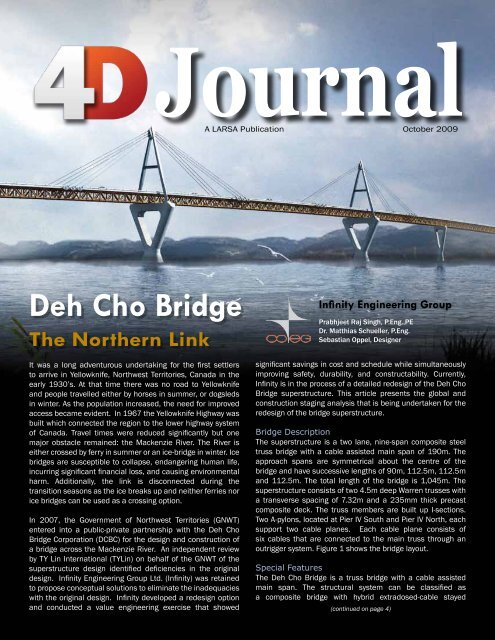
Deh Cho Bridge<br />
The Northern Link<br />
It was a long adventurous undertaking for the first settlers<br />
to arrive in Yellowknife, Northwest Territories, Canada in the<br />
early 1930’s. At that time there was no road to Yellowknife<br />
and people travelled either by horses in summer, or dogsleds<br />
in winter. As the population increased, the need for improved<br />
access became evident. In 1967 the Yellowknife Highway was<br />
built which connected the region to the lower highway system<br />
of Canada. Travel times were reduced significantly but one<br />
major obstacle remained: the Mackenzie River. The River is<br />
either crossed by ferry in summer or an ice-bridge in winter. Ice<br />
bridges are susceptible to collapse, endangering human life,<br />
incurring significant financial loss, and causing environmental<br />
harm. Additionally, the link is disconnected during the<br />
transition seasons as the ice breaks up and neither ferries nor<br />
ice bridges can be used as a crossing option.<br />
In 2007, the Government of Northwest Territories (GNWT)<br />
entered into a public-private partnership with the Deh Cho<br />
Bridge Corporation (DCBC) for the design and construction of<br />
a bridge across the Mackenzie River. An independent review<br />
by TY Lin International (TYLin) on behalf of the GNWT of the<br />
superstructure design identified deficiencies in the original<br />
design. Infinity Engineering Group Ltd. (Infinity) was retained<br />
to propose conceptual solutions to eliminate the inadequacies<br />
with the original design. Infinity developed a redesign option<br />
and conducted a value engineering exercise that showed<br />
<strong>Journal</strong><br />
A LARSA Publication October 2009<br />
Infinity Engineering Group<br />
Prabhjeet Raj Singh, P.Eng.,PE<br />
Dr. Matthias Schueller, P.Eng.<br />
Sebastian Oppel, Designer<br />
significant savings in cost and schedule while simultaneously<br />
improving safety, durability, and constructability. Currently,<br />
Infinity is in the process of a detailed redesign of the Deh Cho<br />
Bridge superstructure. This article presents the global and<br />
construction staging analysis that is being undertaken for the<br />
redesign of the bridge superstructure.<br />
Bridge Description<br />
The superstructure is a two lane, nine-span composite steel<br />
truss bridge with a cable assisted main span of 190m. The<br />
approach spans are symmetrical about the centre of the<br />
bridge and have successive lengths of 90m, 112.5m, 112.5m<br />
and 112.5m. The total length of the bridge is 1,045m. The<br />
superstructure consists of two 4.5m deep Warren trusses with<br />
a transverse spacing of 7.32m and a 235mm thick precast<br />
composite deck. The truss members are built up I-sections.<br />
Two A-pylons, located at Pier IV South and Pier IV North, each<br />
support two cable planes. Each cable plane consists of<br />
six cables that are connected to the main truss through an<br />
outrigger system. Figure 1 shows the bridge layout.<br />
Special Features<br />
The Deh Cho Bridge is a truss bridge with a cable assisted<br />
main span. The structural system can be classified as<br />
a composite bridge with hybrid extradosed-cable stayed<br />
(continued on page 4)
Welcome to the imension<br />
Come visit us at our booth at the following upcoming<br />
conferences:<br />
21st Annual ASBI Symposium<br />
October 25-27, 2009<br />
Hilton Hotel<br />
Minneapolis, MN<br />
World Steel Bridge Symposium<br />
November 17-20, 2009<br />
Henry B. Gonzalez Convention Center<br />
San Antonio, TX<br />
International Bridge Conference<br />
June 6-9, 2010<br />
David L. Lawrence Convention Center<br />
Pittsburgh, PA<br />
LARSA, Inc.<br />
105 Maxess Road<br />
Melville | New York | 11747<br />
1-212-736-4326<br />
www.LARSA4D.com<br />
info@LARSA4D.com<br />
This year has been an exciting year for the LARSA 4D team. We have delivered a very impressive list<br />
of features to our users in the new versions of LARSA 4D, and we saw a significant increase in the<br />
use of 4D analysis beyond segmental and cable-stay bridge structures.<br />
As our clients find LARSA 4D well-suited to the complexities of modern bridge design of the 21st<br />
century, it is very exciting to see more users have started serious development of their own macros<br />
taking advantage of LARSA 4D’s unique macro environment to improve their performance on their<br />
projects.<br />
We have a long list to deliver on in 2010 including time-dependent composite construction based on<br />
a layered approach with no practical set limit for the number of layers. Our world-class team shall<br />
continue working to support our clients with the same forward-thinking technology that has made<br />
LARSA 4D so unique.<br />
Best of Luck,<br />
Visit Us<br />
Meet the Team<br />
Anita Sarrafian is LARSA, Inc’s Marketing and Design Associate.<br />
She is a graduate of Stony Brook University and has used her<br />
knowledge of art and design to transform LARSA’s brand. Her<br />
responsibilities include the creation of all of LARSA’s print<br />
media, including this journal as well as the maintenance and<br />
development of the LARSA image.<br />
th<br />
LARSA 4D is analysis and design software for bridges, buildings, and other<br />
structures, developed by LARSA, Inc. in New York, USA.<br />
This journal is distributed as a courtesy to our clients and corporate friends.<br />
We welcome feedback and suggestions for future stories to info@LARSA4D.com.<br />
•LARSA’s 4D <strong>Journal</strong>•October 2009•Page 2<br />
Ali D. Karakaplan, Eng. Sc.D<br />
President, LARSA, Inc.<br />
Announcements<br />
We have posted new and updated documentation on our<br />
website (www.larsa4d.com). The documentation includes<br />
three new training manuals: a basic LARSA 4D training<br />
manual, an introductory training manual for bridge projects,<br />
and an advanced training manual for bridge projects. Manuals<br />
for LARSA Section Composer and macro development are also<br />
available, along with an updated User’s Guide and Reference<br />
Manual.<br />
In The Works<br />
LARSA’s development team is continually working to provide<br />
new innovative tools for structural analysis. Here is what we’re<br />
working on now:<br />
Influence Analysis: We will soon be including an updated<br />
influence line and surface analysis that is faster and more<br />
accurate. The analysis will also have a new entry for centrifugal<br />
force factors and will now support AASHTO LFD for influence<br />
surfaces with multiple design lanes. The analysis will also take<br />
advantage of the additional computing power of multi-core/<br />
multiple-CPU computers.<br />
Front Cover: Infinity Engineering Group, North Vancouver, Canada
{ }<br />
Expanding the Possibilities<br />
Using Macros in LARSA 4D<br />
LARSA 4D is a powerful package containing many built-in<br />
features but for those who demand further automation, it also<br />
offers a flexible platform allowing users to extend LARSA 4D to<br />
do almost anything imaginable. Extending LARSA 4D has the<br />
following advantages:<br />
• ability to perform custom and/or complex operations in single steps<br />
• saving time in performing repeated actions<br />
• automating model generations<br />
• batch result extraction and custom formatting<br />
• ability to incorporate custom design checks<br />
• ability to incorporate yet-unforeseen features<br />
As a simple example, to calculate the total weight of a<br />
structure, you would need to run static analysis with self<br />
weight and add up the reactions manually. This procedure,<br />
however, can be added into LARSA 4D as a simple plug-in or<br />
automated using a short macro so that no analysis or manual<br />
computation is required. This task is implemented by the short<br />
Weight = 0<br />
For i = 1 To project.Members.Count<br />
Dim m As Object: Set m = project.Members.<br />
itemByIndex(i)<br />
Weight = Weight + m.Length * m.section(1).<br />
sectionArea * m.material.unitWeight<br />
Next<br />
MsgBox “Weight of the structure is “ & Weight<br />
VBA macro shown above which can<br />
be entered into and run in Microsoft<br />
Excel with LARSA 4D running.<br />
The first line of the code above<br />
creates a variable, initially set to<br />
zero, that will accumulate a running<br />
total of weight. The second and third<br />
lines of the code create a loop, going<br />
over all the member elements in<br />
the structure. That means each line<br />
between For and Next is repeated<br />
over and over for each member in<br />
the model. On the fourth line, the<br />
weight of each member is computed<br />
by multiplying its length by its cross-<br />
by Ali Koc (a.k.a. “Koch”)<br />
Director of Research, Development & Support<br />
•LARSA’s 4D <strong>Journal</strong>•October 2009•Page 3<br />
sectional area by its density, and that is added into the Weight<br />
variable. Finally on the sixth line, the accumulated weight is<br />
displayed to user in a pop-up message box.<br />
The main distinction between plug-ins and macros is the way<br />
they communicate with LARSA 4D. Using macros, you can<br />
implement functionality that accesses (and can modify) all the<br />
internal data and functionality of LARSA 4D, but it is written<br />
and run externally to LARSA 4D, usually in Microsoft Excel’s<br />
VBA macro editor. Since almost all LARSA 4D users are familiar<br />
with Microsoft Excel, it is practically a standard choice as the<br />
platform for LARSA 4D macro development.<br />
A LARSA 4D plug-in is a step forward from macros in terms of its<br />
tight integration with LARSA 4D. They compile into a separate<br />
module (a .dll file) and are automatically loaded by LARSA 4D<br />
at startup. Each plug-in can have its own menu items within<br />
LARSA 4D menus. They have direct integration with graphics<br />
windows, explorers and spreadsheets of LARSA 4D. They are<br />
also capable of displaying their own user interface windows<br />
within the application. This system is used even by our own<br />
developers -- in fact, most of the design modules in LARSA 4D<br />
are plug-ins.<br />
Though Visual Basic and VBA are the coding languages of<br />
choice for almost all macros and plug-ins developed for LARSA<br />
4D, it is possible to use any language or platform supporting<br />
Microsoft COM technology. That includes scripting languages<br />
such as VBScript, JavaScript or lower level languages such as<br />
FORTRAN, C, C++. There are some plug-ins developed even in<br />
.NET languages, such as C# and VB.NET.<br />
(continued on page 6)<br />
A sample macro screen in Microsoft Excel
Deh-Cho Bridge (continued from page 1)<br />
features. Comparable to a cable stayed system, the primary<br />
purpose of the cables is to support the truss in spanning the<br />
190 m navigation channel. However, contrary to a cable stayed<br />
system the backstays are not anchored at a pier location. The<br />
backstays function by activating the bending stiffness of the<br />
truss similar to an extradosed system.<br />
The value engineering provided by Infinity led to the following<br />
features. The articulation scheme chosen allows a continuous<br />
and jointless deck for length of the entire superstructure over<br />
1 km. The deck is built from precast concrete panels with cast<br />
in place infills. A combination of a waterproofing membrane<br />
with two layers of asphalt is applied to the surface for sealing<br />
purposes. Compact lock coiled cables have been used for the<br />
stay system. They have simplified anchorages that can be<br />
easily inspected and maintained.<br />
Design Philosophy<br />
The design philosophy adopted for the Deh Cho Bridge consists<br />
of the Big Picture Approach, the Failure Mechanism Concept,<br />
and the Redundancy & Integrity Rule.<br />
A Big Picture Approach was adopted for the design of the Deh<br />
Cho Bridge. Special consideration was given to the following<br />
aspects: functionality, safety, durability, constructability, cost,<br />
maintenance and aesthetics. Member profiles and materials<br />
were selected for their efficiency in resisting the primary force<br />
effects they experience. As an example, the bottom chord is<br />
an optimized I-profile resisting axial demands during service<br />
and in addition bending during launching. The dead load to<br />
payload ratio is minimized through the principles of lightweight<br />
design. The primary structural objective was to tune the system<br />
to be flexible for temperature effects while at the same time<br />
being stiff for live and wind loads.<br />
The Failure Mechanism Concept was applied to ensure that<br />
the structure does not experience a sudden collapse under<br />
any given load scenarios. The primary load paths are designed<br />
for a controlled failure mechanism. The load travels through<br />
a series of structural components comparable to a structural<br />
chain. The weakest link in the chain is determined by the<br />
designer and engineered to fail with adequate warning (ductile<br />
behavior). For example, the cable anchorage and attachments<br />
are designed for the minimum breaking load of the cable,<br />
Figure 1: General Arrangement<br />
Figure 2: Unbalanced System, Dead Load and Cable Tensioning applied<br />
•LARSA’s 4D <strong>Journal</strong>•October 2009•Page 4<br />
making the cables the crucial component of this particular<br />
load path.<br />
Redundancy stands for alternate load paths provided by the<br />
designer. The Post-Tensioning Institute (PTI) recommends<br />
that the designer considers cable loss scenarios. For those<br />
extreme events the designer should ensure that the Integrity<br />
of the bridge is not endangered.<br />
Analysis<br />
The analysis undertaken for the project included a global<br />
analysis of the entire bridge, an erection staging analysis<br />
and local finite element analyses for specific connections<br />
and details. The focus of this article is on the global and<br />
erection staging analysis. The work is being performed under<br />
an accelerated schedule which requires a user friendly and<br />
powerful analysis tool supporting the design.<br />
Global Analysis<br />
A three-dimensional model was created that included the<br />
entire bridge consisting of foundations, piers & abutments,<br />
bearings, truss, pylons, cables and deck. The global analysis<br />
was conducted with LARSA 4D.<br />
Tuning<br />
The first step in the global analysis was to tune the dead load<br />
sharing in the truss and the cables to obtain a beneficial<br />
behavior. An accurate estimate of the cable force was obtained<br />
by making all the members infinitely stiff under dead load.<br />
The preliminary cable size was determined using the dead<br />
load cable force and a contingency for transitory loads. The<br />
properties of the cables thus determined were used in the<br />
model together with the real stiffness of all other members.<br />
The cable elongation under dead load was compensated using<br />
a temperature load case using the following formula:<br />
∆T = - σDL / (E αT )<br />
with: ∆T = compensating temperature<br />
σDL = cable stress under dead load<br />
E = modulus of elasticity of the cable<br />
αT = temperature coefficient for the cable
Truss Camber<br />
The span arrangement of the Deh Cho Bridge requires a truss<br />
camber at the cable support locations. The span supported<br />
by the back stays is only 112.5 m while the span supported<br />
by the front stays is 190 m. This uneven configuration results<br />
in unbalanced cable forces in the front and back stays, and<br />
thus causes a tower rotation to find equilibrium, see Figure 2.<br />
Since the back stays are not connected to a fixed point such as<br />
an anchor pier, typical for cable-stayed bridges, truss uplift at<br />
the backspan cable support cannot be compensated by cable<br />
force manipulation.<br />
To achieve the given roadway profile the truss needed to be<br />
cambered down in the backspan. The truss camber for half the<br />
bridge is shown in Figure 3.<br />
The truss camber shown in Figure 3 compensates the<br />
permanent load deflections shown in Figure 2 resulting in the<br />
desired roadway profile, see Figure 4.<br />
Loads<br />
Influence surfaces were used to determine the maximum force<br />
effects from moving loads. An influence surface, or 3-D grid of<br />
influence coefficients, is created by running a unit load over<br />
a predefined load area (typically traffic lanes). An influence<br />
surface can be generated for a force effect (i.e. bending, shear,<br />
Figure 5: Influence Surface<br />
Figure 3: Truss Camber<br />
•LARSA’s 4D <strong>Journal</strong>•October 2009•Page 5<br />
compression etc.) at any cross-section of a component of the<br />
structure. The magnitude of the force effect from a vehicle<br />
placed anywhere on the load area is determined from the<br />
influence coefficients and the vehicle loads. Ultimately, the<br />
vehicle is positioned on the influence surface to maximize the<br />
force effects under consideration. The influence surface for<br />
the bottom chord in the center of hanging span can be seen in<br />
Figure 5. The corresponding deformation for a truck positioned<br />
in the most unfavorable location is shown in Figure 6.<br />
Horizontal Load Effects<br />
Figure 4: Camber, Shortening Cables and Dead Load applied<br />
Figure 6: Deformed Bridge<br />
Two separate models were created to represent the different<br />
articulation scenarios depending on the nature of horizontal<br />
load effects. The bridge is fixed transversely at the piers<br />
and abutments. The continuous superstructure requires<br />
both flexibility for movements and fixity for load sharing of<br />
longitudinal loads. This contradiction has been resolved by<br />
the use of lock-up-devices (LUDs) that release temperature<br />
restraining effects but engage the piers for external load<br />
effects such as wind and braking loads.<br />
The master-slave joint feature of the software was used to<br />
model the articulation. The use of master-slave joints provides<br />
the option to couple or un-couple any of the six degrees of<br />
freedom to model various articulation conditions.<br />
Erection Analysis<br />
The designer shall consider at least one feasible construction<br />
method in the analysis of complex bridges. For the Deh Cho<br />
Bridge the following erection stages have been incorporated<br />
into the design:<br />
• Launching 494 m long truss approaches from each abutment<br />
• Installation of A-pylons and cables<br />
• One-step stressing of all cables simultaneously by lowering truss at pier 4<br />
• Deck panel installation up to pier 4<br />
• Installation of 57 m long lifting span<br />
• Deck panel installation in the main span<br />
• Activation of composite action<br />
• Casting curb and installation of railing<br />
• Installation of waterproofing and wearing surface<br />
A staged analysis for the launch was performed. The effect<br />
(continued on page 6)
Deh-Cho Bridge<br />
Figure 7: Typical Launch Stage<br />
of camber was included in the analysis using a temperature<br />
load case. This method has the advantage of being able to<br />
stages before.<br />
turn camber off when the truss is moved ahead and connected Conclusion<br />
to the supports in the new location. About 130 launch stages The Deh Cho Bridge is a major long span crossing that requires<br />
were analyzed and summarized in demand envelopes. A rigorous analysis. LARSA 4D has proven to be an effective tool<br />
typical stage is shown in Figure 7.<br />
Using Macros<br />
(continued from page 5)<br />
After erection of the A-pylon is completed, the truss is jacked<br />
up at pier 4 to facilitate installation of the cables. Thereafter,<br />
the truss is lowered to its final position stressing all cables<br />
simultaneously, see Figure 8.<br />
The lifting span splice requires geometric compatibility of<br />
the truss ends, see Figure 9. This is achieved by loading the<br />
backspan through placing deck panels from the abutment<br />
to pier 4. The design takes into account the construction<br />
demands including forces, deflections and rotations from the<br />
(continued from page 3)<br />
Today, developing macros is a routine part of the LARSA<br />
4D technical support process. The complexity of the<br />
macros created for technical support solutions ranges<br />
from a simple spreadsheet reporting the angle between<br />
some deformed members to full blown model generation,<br />
analysis extraction, and design checks. For example, there<br />
is a macro for the generation, analysis and design of guyed<br />
towers in LARSA 4D. We have made tens of macros for<br />
generating variety of models such as steel plate girder<br />
bridges, segmental bridges and cable stayed bridges.<br />
Some of the macros are for inputting data. These macros,<br />
for example, allow users to input tendon geometry in global<br />
Figure 8: One Step Stressing of Cables<br />
Figure 9: Lifting Span Operation<br />
•LARSA’s 4D <strong>Journal</strong>•October 2009•Page 6<br />
to support the design in the conceptual and detailed design<br />
stages. This article focused on cable tuning and an analysis for<br />
camber, live load and other transitory loads. In addition, the<br />
analysis for a staged erection concept has been presented.<br />
This investigation consisted of truss launching, cable stressing<br />
and a lifting span operation.<br />
The overall project success depends decisively on the analysis<br />
tools employed. In today’s market with aggressive timelines<br />
engineers rely heavily on the efficiency of programs and<br />
the support provided by the software developer. LARSA 4D<br />
delivered both: the tool and the support.•<br />
Infinity Engineering Group based in North Vancouver, Canada specializes in the design and erection engineering of bridges. The experience of their team has<br />
been developed through work on many bridge projects including complex curved and long span cable supported grade separations. Infinity Engineering Group is<br />
committed to understanding the client’s needs and working within the necessary budgets and schedules.<br />
coordinates, or directly import it from DXF CAD files. Using<br />
these macros, user can automatically set up staged<br />
construction data, generate loading for nonlinear live load, or<br />
setup incremental launching sequence of a segmental bridge.<br />
By having direct access to the model, analysis results and<br />
the full feature set of LARSA 4D, these macros are capable<br />
of performing even more complex tasks, such as iterative<br />
shape finding, flexibility matrix generation, and reverse staged<br />
construction.<br />
Whatever your need may be, this flexible platform can be<br />
utilized to not only carry out the required task, but also perform<br />
it in a customized format suitable to your specific work style.•
Cable Tension Optimization<br />
A common problem in<br />
the analysis of a cablestayed<br />
bridge is the<br />
determination of initial<br />
cable tension forces<br />
that — in combination<br />
with other loading, the<br />
construction sequence,<br />
and time-dependent<br />
material effects — gives<br />
the structure its desired<br />
final geometry and<br />
internal forces. LARSA 4D<br />
Bridge Plus provides two<br />
solutions to this process.<br />
The first determines cable<br />
tension forces in a model<br />
in which the structure<br />
is constructed in a single step. The second is based on the<br />
unit-load method and is used for models with a construction<br />
sequence.<br />
We call these procedures model optimization. Optimization is<br />
the term from mathematics of finding a minimum of a function.<br />
These procedures are used in LARSA 4D to minimize deflection.<br />
Iteration Using Final Cable Tension<br />
In a nonlinear structure such as one with cables, one cannot<br />
solve directly for the set of cable forces at cable installation<br />
Figure 1. Flow chart of the method to iterate using final<br />
cable tension.<br />
by Josh Tauberer<br />
Director of Software Architecture<br />
•LARSA’s 4D <strong>Journal</strong>•October 2009•Page 7<br />
that is needed to achieve<br />
a chosen deformed state<br />
once other loading has<br />
been applied. If all of<br />
the deformation on the<br />
structure takes place after<br />
the cable is tensioned,<br />
and the goal is to have the<br />
base of the cable stay at<br />
its undeformed location,<br />
then one can make use<br />
of the fact that the cable<br />
jacking force will match<br />
exactly with the final<br />
tension in the cable. If<br />
there is no change in axial<br />
force, the cable has not<br />
deformed.<br />
A simple procedure that has been carried out by engineers<br />
by hand has been to start the cables with minimal jacking<br />
force, solve for the axial forces in the cables at the end of<br />
construction, take those axial forces and use them as the<br />
cable jacking forces the next time around, and then repeat this<br />
process until the tensile forces no longer change as a result of<br />
other loading on the structure. The procedure is illustrated in<br />
Figure 1.<br />
To see why this might work, take the case of a single cable<br />
holding up a deck. If the initial cable force is not great enough<br />
to hold up the deck, the deck will lower causing the force in<br />
the cable to increase. If the cable is jacked too much, the deck<br />
will raise and the cable will shorten, causing the cable force to<br />
decrease. When the deck is held up in place, the cable does<br />
not deform and there is no change in axial force.<br />
We can think of the static analysis as a function f(x), where x<br />
is the initial cable force (“pretension” in LARSA 4D) and f(x)<br />
is the cable tension after other loading has been applied (the<br />
Fx member end force). The goal is to find x such that f(x) = x.<br />
If there is more than one cable, we can think of f as a function<br />
from a vector of cable jacking forces x to a vector of final cable<br />
tension values f(x).<br />
This procedure is automated in LARSA 4D.<br />
In a typical nine-cable cable-stayed bridge model, we have<br />
found that the process requires only roughly five iterations to<br />
achieve near-zero displacements. A perfect solution may be<br />
(continued on page 8)
(continued from page 7)<br />
impossible due to other structural elements in the model, and<br />
in this case the procedure could be left to adjust pretension<br />
values indefinitely. The cable pretension values for the nine<br />
cables in a typical model after each iteration are shown in<br />
Figure 2. At the first iteration the cables are all set to a common<br />
initial prestress force.<br />
Iteration Using Unit Loading and a Flexibility Matrix<br />
In a segmental assembly a cable may be installed after its<br />
segment has already deformed due to dead load. The goal<br />
here is to achieve zero joint displacement, but because the<br />
cable is installed in the middle of the construction sequence<br />
the cable is intended to deform as it brings the joint back up to<br />
its initial location. Since the cable will deform, the initial cable<br />
tension will not match final cable tension, the first procedure is<br />
not applicable in this case.<br />
A different method is required in this case. The “unit load<br />
method” has been applied in the past to solve this problem. In<br />
this method, we apply a unit-tug — i.e. one extra unit of jacking<br />
force — to each cable and observe its effect on each of the<br />
joints at the bases of the cables (or any other joints on the<br />
deck). Then we solve for a factor to apply to the tug to zero-out<br />
the displacements at a joint. Take the case of a single cable.<br />
At the initial condition, the joint at the base of the cable has<br />
displaced by 5 meters. Through a static analysis we determine<br />
that adding 1 kN of force to the cable raises the joint by 1<br />
meter. We then conclude that 5 times the 1 kN = 5 kN will raise<br />
the joint back to its undeformed location. If the structure has<br />
nonlinear behavior 5 kN may not have the effect of 5 times<br />
the effect of 1 kN, so the process must be iterated until the<br />
displacement comes within tolerable limits.<br />
Figure 2. Cable pretension values for nine cables after the<br />
first 35 iterations.<br />
This is the application of a procedure used in many other fields<br />
of applied mathematics and is a generalization into multiple<br />
dimensions of the Newton-Raphson method of finding the<br />
solution to f(x) = 0. As opposed to the first iterative method<br />
described above, f(x) here is a function from a vector of cable<br />
pretension forces to a vector of joint deformations in the<br />
elevation axis.<br />
The Newton-Raphson method can be summarized as follows:<br />
when searching values of x for the one that makes f(x) = 0, a<br />
•LARSA’s 4D <strong>Journal</strong>•October 2009•Page 8<br />
good guess is to use the slope of f to predict where the function<br />
is going. This is shown in Figure 3, and formally in Equations<br />
1–2, where f´ denotes the derivative of f.<br />
eqn 1. f´(x) . ∆x = -f(x)<br />
eqn 2. ∆x = f(x)<br />
f´(x)<br />
When there is more than one cable this process must be<br />
generalized to multiple dimensions, and the iterative step is<br />
derived as shown in Equations 3–4. The matrix J, called the<br />
Jacobian matrix, represents the slope of the function in each<br />
dimension. J ij is the change in displacement at joint i due to<br />
a one-unit tug on cable j. ∆x is the computed additional initial<br />
cable tension that is needed and is added in at the end of the<br />
current iteration.<br />
eqn 3. J . ∆x = -f(x)<br />
eqn 4. ∆x = -J -1 f(x)<br />
J is computed by running a separate static analysis for each<br />
column of the matrix. Each analysis applies a one-unit tug<br />
u i to each cable at the time it is installed, within a Staged<br />
Construction Analysis already set up by the user that might<br />
additionally contain dead load, time-dependent material<br />
effects, and other nonlinear behavior. For each analysis we<br />
record the displacement of the joints at the bases of the cables<br />
at the end of construction (i.e. at the final construction step)<br />
and subtract off the corresponding displacements without the<br />
unit tug.<br />
-f(x)<br />
first iteration<br />
x x′<br />
∆ x<br />
second iteration<br />
solution<br />
Figure 3. Illustration of Newton-Raphson<br />
in one dimension.<br />
The cable jacking forces can be applied at different times, i.e.<br />
at different stages during a construction analysis that takes<br />
into account time-dependent material properties, temporary<br />
loading, other construction activities, and geometric<br />
nonlinearity. The algorithm will find whatever pretension force<br />
such that the deformations work out at the end.<br />
More details on using these tools can be found in the<br />
documentation section of our website http://www.larsa4d.<br />
com.•<br />
f