

Manual - Maintenance Electronique / Monitors Service Center
Manual - Maintenance Electronique / Monitors Service Center
Manual - Maintenance Electronique / Monitors Service Center

You also want an ePaper? Increase the reach of your titles
YUMPU automatically turns print PDFs into web optimized ePapers that Google loves.
5 Disassembly and Reassembly<br />
5-1-2 Removing the Entire PCB Assembly<br />
1. Complete all previous steps.<br />
2. Using pinch-nosed pliers or long-nosed pliers,<br />
carefully disconnect the Anode Cap from the<br />
CRT.<br />
3. Disconnect connector GTP901 on the CRT<br />
Socket PCB.<br />
4. Disconnect the CRT Socket PCB Assembly.<br />
5. Disconnect connectors CN401_1~CN401_4,<br />
C301_1~CN301_3, CN403, CN404 and CN405<br />
on the Main PCB and CN605, CN606 on the<br />
Power PCB.<br />
Figure 5-5<br />
6. Remove the 3 screws on the Main PCB Chassis<br />
Bracket.<br />
7. Lift off the entire PCB Assembly and place it<br />
on a flat, level surface that is protected from<br />
Static electricity.<br />
Figure 5-6<br />
5-1-3 Removing the CRT Socket PCB<br />
1. Complete all previous steps.<br />
2. Disconnect connectors CN104B, CN104RG and<br />
G2 (GTP902) on the CRT Socket PCB.<br />
3. Hold the CRT Socket PCB Assembly while<br />
you lift the Cap on the CRT Socket and<br />
desolder the two focus wires.<br />
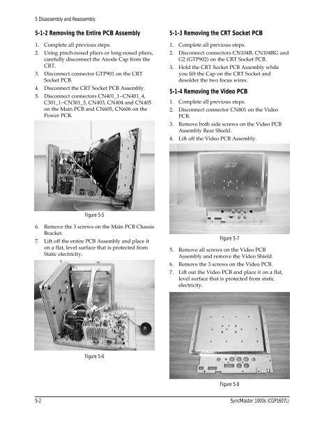
5-1-4 Removing the Video PCB<br />
1. Complete all previous steps.<br />
2. Disconnect connector CN801 on the Video<br />
PCB.<br />
3. Remove both side screws on the Video PCB<br />
Assembly Rear Shield.<br />
4. Lift off the Video PCB Assembly.<br />
Figure 5-7<br />
5. Remove all screws on the Video PCB<br />
Assembly and remove the Video Shield.<br />
6. Remove the 3 screws on the Video PCB.<br />
7. Lift out the Video PCB and place it on a flat,<br />
level surface that is protected from static<br />
electricity.<br />
Figure 5-8<br />
5-2 SyncMaster 1000s (CGP1607L)