Operation manual Track System TRUMPF 95 - Gerriets
Operation manual Track System TRUMPF 95 - Gerriets
Operation manual Track System TRUMPF 95 - Gerriets

You also want an ePaper? Increase the reach of your titles
YUMPU automatically turns print PDFs into web optimized ePapers that Google loves.
E<br />
<strong>Operation</strong> Manual<br />
<strong>Track</strong> <strong>System</strong> <strong>TRUMPF</strong> <strong>95</strong><br />
Technic
1-4 Contents<br />
1<br />
2<br />
3<br />
4<br />
2<br />
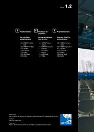
Introduction<br />
<strong>System</strong> Installation<br />
<strong>System</strong> <strong>Operation</strong><br />
Safety Instructions<br />
Contents Page<br />
1.1 General Instructions 3<br />
1.2 Approved Use of <strong>System</strong> 3<br />
1.3 Unapproved Use of <strong>System</strong> – Safety Risks 3<br />
1.4 Technical Data 4<br />
1.5 Further Information 4<br />
1.6 <strong>System</strong> Options 4<br />
1.7 Safety Instructions 5<br />
2.1 Installation 5<br />
2.2 Preparation 5<br />
2.2.1 Delivery of <strong>System</strong> 5<br />
2.2.2 <strong>System</strong> Design 5 - 6<br />
2.3 <strong>Track</strong> Mounting 7 - 29<br />
2.3.1 <strong>System</strong> Parts Mounting 7 - 9<br />
• Walk-Along <strong>System</strong> 10 - 15<br />
• Side Cord <strong>Operation</strong> 16 - 19<br />
• Top Cord <strong>Operation</strong> 20 - 23<br />
• Double Top Cord <strong>Operation</strong> 24 - 28<br />
• Motors 28 - 30<br />
2.3.2 Rope Attachment 31<br />
2.3.3 Rope <strong>Operation</strong> Test 31<br />
2.3.4 Curtain Attachment 31<br />
2.3.5 Curtain <strong>Operation</strong> Test 31<br />
2.3.6 Motor Installation 32<br />
2.3.7 <strong>System</strong> <strong>Operation</strong> 32<br />
3.1 Operator Instructions 33<br />
3.2 Instruction of Untrained Persons Working Area 33<br />
3.3 Maintenance 33<br />
3.4 <strong>System</strong> Modifications 33<br />
4.1 Safety Risks of Approved Uses 34<br />
<strong>Operation</strong> Manual / <strong>TRUMPF</strong> <strong>95</strong><br />
Information<br />
All information subject to change or<br />
technical modification without notice.<br />
(Updated 05/2010)
1 Introduction<br />
1.1 General Instructions<br />
Applications<br />
<strong>Operation</strong> Manual<br />
1.2 Approved Use of <strong>System</strong><br />
1.3 Unapproved Use of <strong>System</strong><br />
<strong>TRUMPF</strong> <strong>95</strong> is a track system for medium- and heavy-duty applications.<br />
A top groove on track allows easy mounting of all accessories.<br />
Installation options:<br />
• Direct ceiling mounting.<br />
• Hook clamp installation for use on truss and pipe battens.<br />
• Wall mount bracket installation.<br />
Perfect for stage and studio. Allows complex configurations such as curves and<br />
switching points.<br />
During events and on stage, there are always people in the curtain area. Operators of a<br />
<strong>TRUMPF</strong> <strong>95</strong> track system must know and follow the special safety regulations for each<br />
production. Possible risks during a production must be understood and guidelines put in<br />
place to minimize accidents.<br />
Please pay attention to following safety standards:<br />
• BGV C1 / GUV-V C1<br />
• BGI 810-0<br />
• BGI 810-2<br />
• DIN 56<strong>95</strong>0<br />
• DIN 60204-1<br />
This operation <strong>manual</strong> is included in the delivery of the <strong>TRUMPF</strong> <strong>95</strong> track system. It<br />
includes all necessary instructions to assemble and to operate the track system safely<br />
and to prevent accidents or damage.<br />
<strong>TRUMPF</strong> <strong>95</strong> is approved for supporting and moving curtains and light-weight scenery<br />
within the maximum load capacity of the track and the associated components. Do not<br />
exceed load rating of track and runners.<br />
The track system load capacity refers to textile curtains applications. For light-weight<br />
scenery applications, specific runners must be used.<br />
<strong>TRUMPF</strong> <strong>95</strong> is not approved for supporting or moving (flying) people. Unapproved use<br />
can result in serious injury or death.<br />
<strong>Operation</strong> Manual / <strong>TRUMPF</strong> <strong>95</strong><br />
3
1 Introduction<br />
1.4 Technical Data<br />
1.5 Further Information<br />
1.6 <strong>System</strong> Options<br />
4<br />
Load Capacity<br />
<strong>Track</strong> weight: 900 g/m<br />
<strong>Track</strong> section length: 6,00 m<br />
Maximum distance between hanging points: 2 m<br />
Minimum curve radius: 500 mm<br />
Wheels: ball bearing<br />
Load weight<br />
[kg]<br />
100<br />
90<br />
80<br />
70<br />
60<br />
50<br />
40<br />
30<br />
20<br />
10<br />
0<br />
Verify the load capacity and stability of the ceiling structure and all attachment<br />
accessories.<br />
<strong>System</strong> Design The load capacity of the overall <strong>TRUMPF</strong> <strong>95</strong> system is determined by the system’s<br />
weakest link. Do not load any component up to the maximum load capacity as there is a<br />
risk of overloading hanging points.<br />
The track system should be designed with the load capacity of the hanging points:<br />
The track system’s load (point load or uniform distributed load) is secured by the<br />
hanging points.<br />
The center hanging points’ weight load is higher than the weight load of the hanging<br />
points at the end of the track.<br />
The load capacity of the hanging points depend on the mounting nuts used. Replacing a<br />
standard camlock nut with an adjustable nut or a HD nut can increase the load capacity.<br />
If you still need a higher load capacity, or a replacement is not possible, you must<br />
reduce the distance between the hanging points.<br />
To define the maximum hanging point distance for a given load weight, see the diagram<br />
in chapter 1.4.<br />
You can find further information, such as load capacity, dimensions and weight of all<br />
track system parts in chapter “2.3 <strong>Track</strong> Mounting”, in the <strong>Gerriets</strong> Technic <strong>manual</strong> and<br />
on our website www.gerriets.com.<br />
Manual or motor operation and control systems:<br />
camlock nut:<br />
standard<br />
Art. 3115 0091<br />
adjustable nut<br />
Art. 3115 0071<br />
HD adjustable nut<br />
Art. 3115 0061<br />
0,00 0,50 1,00 1,50 2,00 (max.)<br />
hanging point distance [m]<br />
• ROPE-DRIVE: Manual operation with a continuous loop hemp rope Ø 22 mm.<br />
• HAND-DRIVE: <strong>manual</strong> operation with hand crank.<br />
• FRICTION-DRIVE: motor operation without rope.<br />
Motor moves via drive wheel along the track.<br />
• TRAC-DRIVE: Motor operation with continuous loop rope.<br />
• G-FRAME 54 control unit.<br />
• G-FRAME 54 frequency controller.<br />
• Hand held remote control.<br />
• <strong>Track</strong> switch, 2 positions, <strong>manual</strong> or motor operation, available with switch controller.<br />
• <strong>Track</strong> switch, 3 positions, <strong>manual</strong> or motor operation, available with switch controller.<br />
<strong>Operation</strong> Manual / <strong>TRUMPF</strong> <strong>95</strong>
2 <strong>System</strong> Installation<br />
1.7 Safety Instructions The operator is responsible for the system operation. Your <strong>TRUMPF</strong> <strong>95</strong> track system,<br />
delivered by <strong>Gerriets</strong> and installed properly, should pose no safety risk. However, with<br />
any mechanical moving equipment, risk of accident or injury is possible.<br />
2.1 Installation<br />
2.2 Preparation<br />
2.2.1 Delivery of <strong>System</strong><br />
2.2.2 <strong>System</strong> Design<br />
For further information see table 4.1.<br />
The installation should be done by certified technicians only. All installers must follow<br />
the operation instructions.<br />
Not following the operation instructions can damage the system. <strong>Gerriets</strong> GmbH is not<br />
liable for these damages.<br />
Please check immediately that the delivery slip matches the parts received to the<br />
images in chapter “2.3 <strong>Track</strong> Mounting” to verify that the shipment is complete.<br />
For designing your custom track system, please note the following points:<br />
When you determine the track system length you must include the curtain stacking<br />
space (length of each runner and master runner) and length of the needed<br />
components such as end stops, return pulley, head pulley and motors at the ends<br />
of the track system.<br />
Stacking space calculation for each side of curtain:<br />
Number of runners (approx. 4-5 runners per meter) x lengths of each runner<br />
+ length of master runner<br />
+ lengths of head and return pulleys<br />
+ length of end stop (+ motor)<br />
These questions help you to define the correct number and type of hanging points.<br />
• <strong>Track</strong>: what kind of load (point load or uniform distribute load) is appropriate?<br />
• Which system position/application bears the highest load capacity (open curtain,<br />
scenery attached to 1 or to 2 scenery carriers)?<br />
• If considering a span width of less than 2 m: Which is the highest possible load<br />
capacity weight for the most stressed hanging points? Regard your system as a<br />
multi-span girder. The spans next to the center hanging point are loaded with the<br />
maximum load capacity. Multiply the span load weight times 1.375. The result is the<br />
approx. maximum load capacity of the center hanging point.<br />
For further questions please contact our customer service team.<br />
q<br />
or<br />
P<br />
l l<br />
q<br />
or<br />
P<br />
P = Point load q = Uniform distributed load I = Distance between spans<br />
• Does the value exceed the maximum load capacity?<br />
• Use the diagram in chapter 1.4 to verify the maximum span width.<br />
The distance between the track end hanging points and the end of the track should be<br />
as short as possible.<br />
The maximum load capacity of the track system (see diagram in chapter 1.4) or its<br />
components (chapter 2.3.1) must not be exceeded. In addition, pay attention to the load<br />
capacity of each single component. The load capacity of all parts is specified in chapter<br />
2.3.1”<strong>System</strong> Parts Mounting”.<br />
<strong>Operation</strong> Manual / <strong>TRUMPF</strong> <strong>95</strong><br />
5
2 <strong>System</strong> Installation<br />
2.2.2 <strong>System</strong> Design The track system’s load capacity is lower at the joint of two track sections. Place the<br />
hanging points less than 100 mm away from the joints/splice points.<br />
6<br />
Ensure that <strong>TRUMPF</strong> <strong>95</strong> is mounted to a stable structure.<br />
Plan the track configuration including the maximum weight load and define where<br />
accessory parts, such as hang points or rope guides, are mounted in top groove of the<br />
track.<br />
Depending on the site of operation different safety regulations may apply.<br />
<strong>Track</strong> sections can be mounted directly to the ceiling structure or preassembled on the<br />
floor.<br />
The installation location should be secured as to prevent objects from overhead from<br />
falling down.<br />
Please see the system parts mounting instructions in the following chapter.<br />
<strong>Operation</strong> Manual / <strong>TRUMPF</strong> <strong>95</strong>
2 <strong>System</strong> Installation<br />
2.3.1 <strong>TRUMPF</strong> <strong>95</strong>: <strong>System</strong> Parts Mounting<br />
The following pages include drawings and descriptions of the <strong>TRUMPF</strong> <strong>95</strong> track system as well as mounting instructions and useful tips.<br />
Depending on which mounting nut you select, three load capacities are given. These values always refer as following:<br />
• Standard camlock nut (3115 0091) – lowest load capacity.<br />
• Adjustable nut (3115 0071).<br />
• HD adjustable nut (3115 0061) – highest load capacity.<br />
In case the measurements in your copy can not be read clearly, please use the TECHNIC <strong>manual</strong> or go to www.gerriets.com.<br />
<strong>Track</strong> Mounting<br />
Art-No 3115 1011 (1012/1021/1022)<br />
Art-No 3115 0011<br />
Art-No 3110 9115<br />
<strong>Track</strong>, Straight<br />
With groove on top of track for accessories mounting.<br />
• Weight: 900 g/m.<br />
If you shorten a track section, the cut must be straight<br />
and at a right angle. Deburr the cut edge to ensure a<br />
precise joint connection of the track sections.<br />
<strong>Track</strong> Splice<br />
Connects two track sections.<br />
• Weight: 260 g.<br />
Joint Pin<br />
• Ø 2,5 mm x 20 mm.<br />
For precise track section connection (included in standard<br />
delivery).<br />
<strong>Track</strong> sections are centered by 2 joint pins and friction-locked<br />
connected with a track splice.<br />
Before connecting the track sections, slide required<br />
camlock nuts (3115 0071/3115/0061) into top groove<br />
of track.<br />
<strong>Operation</strong> Manual / <strong>TRUMPF</strong> <strong>95</strong><br />
7
2 <strong>System</strong> Installation<br />
2.3.1 <strong>TRUMPF</strong> <strong>95</strong>: <strong>System</strong> Parts Mounting<br />
Art-No 3115 0091<br />
8<br />
Camlock Nut<br />
For accessories mounting. Premounted to all accessories<br />
(M8 x 20 mm screw).<br />
• Weight: 10 g.<br />
• Load capacity in the groove: 45 kg.<br />
• Place the camlock nut where needed in the track groove.<br />
• Loosen screw until almost removed.<br />
• Tighten screw until noticeable resistance. Keep on tightening.<br />
The camlock nut should turn 90° and securely fit into the top<br />
groove of the track.<br />
• Double-check if camlock nut is turned 90° in the<br />
groove of track.<br />
• If the camlock nut is not in the required position<br />
(compare image) repeat the steps above.<br />
<strong>Operation</strong> Manual / <strong>TRUMPF</strong> <strong>95</strong>
2 <strong>System</strong> Installation<br />
2.3.1 <strong>TRUMPF</strong> <strong>95</strong>: <strong>System</strong> Parts Mounting<br />
Art-No 3115 0071<br />
Art-No 3115 0061<br />
Art-No 3115 0011<br />
Adjustable nut<br />
• Positioned in top groove of the track.<br />
• With hole to accept M8 bolt.<br />
• Load capacity in groove: 60 kg.<br />
HD adjustable nut<br />
• For heavy-duty applications. Only for straight applications.<br />
With hole to accept M8 bolt for track mounting.<br />
• Weight: 72 kg.<br />
• Load capacity in groove: 80 kg.<br />
Slide HD adjustable nut in groove of track and secure it at the<br />
desired position by tightening the screws.<br />
End Stop<br />
With hole to attach the curtain camlock nut mounted.<br />
• Weight: 130 g.<br />
<strong>Operation</strong> Manual / <strong>TRUMPF</strong> <strong>95</strong><br />
9
2 <strong>System</strong> Installation<br />
2.3.1 <strong>TRUMPF</strong> <strong>95</strong>: Walk-Along <strong>Track</strong> / Overview<br />
Walk-Along <strong>Track</strong><br />
Mounting Considerations<br />
List of parts for sample system<br />
below<br />
10<br />
<strong>Track</strong> system without motor operation. Manual opening and<br />
closing of the curtain.<br />
The basic track system to move a curtain/scenery along a<br />
track.<br />
Please note height measurements of all components for<br />
system design and installation.<br />
Please calculate length of each runner and master runner for<br />
stacking space.<br />
Art-No Article<br />
3115 1012 <strong>Track</strong>, straight, clear anodized<br />
3100 8011 Hook clamp<br />
31150021 End stop<br />
3100 0061 HD runner with overlap arm<br />
3100 0021 2-wheel runner, black<br />
3100 0031 4-wheel runner<br />
3115 0021<br />
3100 8011<br />
<strong>Operation</strong> Manual / <strong>TRUMPF</strong> <strong>95</strong><br />
3100 0061
2 <strong>System</strong> Installation<br />
3115 1012<br />
3100 0031<br />
End view<br />
140<br />
109<br />
43<br />
34<br />
90<br />
3100 0021<br />
Side view<br />
40<br />
25<br />
<strong>Operation</strong> Manual / <strong>TRUMPF</strong> <strong>95</strong><br />
47<br />
50<br />
11
2 <strong>System</strong> Installation<br />
2.3.1 <strong>TRUMPF</strong> <strong>95</strong>: Walk-Along <strong>Track</strong> / <strong>System</strong> Parts Mounting<br />
Art-No 3100 0031<br />
Art-No 3100 0011<br />
Art-No 3100 0021<br />
Art-No 3115 0031<br />
Art-No 3100 8021 / 3100 8022<br />
12<br />
4-Wheel Runner<br />
Curtain attachment via tie line, carabiners up to 60/6, shackles<br />
or curtain hooks.<br />
• Load capacity: 20 kg.<br />
• Weight: 110 g.<br />
4+4 Master Runner<br />
• Load capacity: 20 kg.<br />
• Weight: 180 g.<br />
2-Wheel Runner<br />
With 360° swivel for curtain attachment via tie line, carabiners,<br />
up to 60/6, shackles or curtain hooks.<br />
• Load capacity: 10 kg.<br />
• Weight: 50 g.<br />
Center Overlap Bracket<br />
For parallel track sections overlap at center (2 to 3 brackets per<br />
overlap). With 12.5 hole to accept hook clamp 3115 8011.<br />
Mounted via 2 camlock nuts (included in delivery).<br />
• Weight: 210 g.<br />
• Load capacity (hook clamp mounting): 80 kg.<br />
Ceiling Mounting Plate<br />
For track systems without cord operation.<br />
For direct ceiling mounting of tracks. With hole to accept M6<br />
bolt (screw and anchor not included).<br />
Distance: every 1-2 m, depending on weight load.<br />
• Weight: 185 g.<br />
• Load capacity: 50 kg.<br />
• For defining the distance between mounting plates,<br />
use load capacity table in chapter 1.4!<br />
• Verify that the ceiling structure and all attachment<br />
accessories such as bolts or anchors are stable<br />
(we recommend using M6 screws in combination<br />
with metal anchors).<br />
• Screw ceiling mounting plate to ceiling.<br />
• Squeeze both plates to the track and tighten<br />
the M4 nuts!<br />
<strong>Operation</strong> Manual / <strong>TRUMPF</strong> <strong>95</strong>
2 <strong>System</strong> Installation<br />
2.3.1 <strong>TRUMPF</strong> <strong>95</strong>: Walk-Along <strong>Track</strong> / <strong>System</strong> Parts Mounting<br />
Art-No 3100 8011<br />
Art-No 3110 8011<br />
Art-No 3115 8021<br />
Art-No 3100 8061 / 3100 8062<br />
Art-No 3115 8071 / 3115 8072<br />
Art-No 3115 8061 / 3115 8062<br />
Hook Clamp, Direct<br />
With attachment kit for direct track mounting (camlock nut and<br />
M8 bolt).<br />
• For pipe battens installation, pipe Ø 48 mm to Ø 60 mm.<br />
• Load capacity: a / b / c *<br />
• Weight: 605 g.<br />
Hook Clamp, Suspension<br />
With attachment kit for mounting directly to suspension<br />
brackets or center overlap brackets.<br />
• For pipe diameter 48-60 mm.<br />
• Load capacity: 45 kg.<br />
For mounting a double track system with center overlap<br />
via hook clamps, off-set mounting plate 3115 8021 is<br />
necessary to align the hook clamps.<br />
Off-Set Mounting Plate<br />
For suspension of a double track with hook clamps (not in<br />
overlap area).<br />
• Load capacity: 45 kg.<br />
Wall Mount Bracket 150 **<br />
With attachment kit for direct track or suspension mounting.<br />
• Wall distance adjustable.<br />
• Length: 150 mm.<br />
• Weight: 465 mm.<br />
• Load capacity: 45 kg.<br />
For use on a walk-along system. If used on a side cord or<br />
top cord system, different attachment kits must be used.<br />
Please note when ordering.<br />
Wall Mount Bracket 250 **<br />
See 3100 8061, with arm length 250 mm.<br />
• Weight 624 g.<br />
• Load capacity: 45 kg.<br />
Wall Mount Bracket 380 **<br />
See 3100 8061, but arm length 380 mm.<br />
• Weight: 1.106 g.<br />
• Load capacity: 30 kg.<br />
<strong>Operation</strong> Manual / <strong>TRUMPF</strong> <strong>95</strong><br />
*<br />
The load capacity of a suspension<br />
point depends on the mounting nut<br />
type:<br />
a = Standard camlock nut: 45 kg<br />
b = Adjustable nut: 60 kg<br />
c = HD adjustable nut: 80 kg<br />
**<br />
Mount the wall mount bracket<br />
securely to the wall with 2 bolts.<br />
Make sure there is sufficient structure<br />
on or behind wall when bolting.<br />
The wall mount bracket must be<br />
securely fastened to the wall before<br />
the track is connected.<br />
13
2 <strong>System</strong> Installation<br />
2.3.1 <strong>TRUMPF</strong> <strong>95</strong>: Walk-Along <strong>Track</strong> / HD Carrier Options<br />
Art-No 3100 0051<br />
Art-No 3100 0071<br />
Art-No 3100 0101<br />
Art-No 3100 0061<br />
14<br />
HD Runner<br />
4 top load bearing and 4 side stabilizing wheels.<br />
With fall protection (in case of load bearing wheels failure).<br />
• Load capacity bis 35 kg. ***<br />
• Weight: 720 g.<br />
HD Scenery Carrier<br />
Technical details: see 3100 0051, but with swivel attachment.<br />
• Weight: 640 g.<br />
• Swivel with M8 bolt for scenery atttachment.<br />
HD Scenery Carrier with Scenery Attachment<br />
Technical details see 3100 0071.<br />
Attachment plates. With 2 holes to accept countersunk bolt,<br />
1 hole to accept 8 mm bolt. For scenery thickness 8-60 mm.<br />
• Weight: 1.009 g.<br />
Scenery Attachment<br />
• If necessary, separate clamping plates from scenery carrier by<br />
removing M5 bolt.<br />
• Attach scenery or scenery frame to clamping plates. Use an<br />
end-to-end M8 bolt for attaching the scenery and wood<br />
screws for positioning the scenery between the clamping<br />
plates.<br />
HD Runner with Overlap Arm<br />
HD runner for up to 35 kg weight load.<br />
For single track systems with center overlap.<br />
• Weight: 815 g.<br />
<strong>Operation</strong> Manual / <strong>TRUMPF</strong> <strong>95</strong><br />
***<br />
Depending on the distance between<br />
suspension points and the mounting<br />
nut type, the weight load must be<br />
below the given runner/carrier load<br />
capacity. Please see diagram in<br />
chapter 1.4.<br />
x1<br />
x2<br />
x1<br />
top view<br />
x1 = 17,5 cm, x2 = 35 cm
2 <strong>System</strong> Installation<br />
2.3.1 <strong>TRUMPF</strong> <strong>95</strong>: Cord <strong>Operation</strong> / Accessories<br />
Art-No 3115 0051<br />
Art-No 3197 0001<br />
Art-No 3115 0041<br />
Art-No 4104 1182<br />
Return Pulley<br />
Returns rope at the end of the track.<br />
Mounted via two camlock nuts (standard delivery)<br />
• For use with rope up to Ø 8 mm.<br />
• Weight: 825 g.<br />
Return and Tensioning Pulley<br />
Return pulley with automatic tensioning of operating rope.<br />
Mounted via 3 camlock nuts (included in standard delivery).<br />
• For use with rope up to Ø 8 mm.<br />
• Tensioning distance: 140 mm.<br />
• Weight: 1250 g.<br />
Head Pulley<br />
Diverts operation cord to floor pulley.<br />
Mounted via 1 camlock nut (standard delivery).<br />
• For use with rope up to max. Ø 8 mm.<br />
Note: Always install 2 suspension points in head<br />
pulley area to reduce stress.<br />
Polyester Rope Ø 8 mm<br />
• Standard rope.<br />
• Works for <strong>manual</strong> operation.<br />
• Color: black (also available in white).<br />
• Tensile strength: approx. 1163 daN.<br />
• Non-stretch.<br />
<strong>Operation</strong> Manual / <strong>TRUMPF</strong> <strong>95</strong><br />
15
2 <strong>System</strong> Installation<br />
2.3.1 <strong>TRUMPF</strong> <strong>95</strong>: Side Cord <strong>Operation</strong> / Overview<br />
Side Cord <strong>Operation</strong><br />
Important<br />
List of parts for Sample <strong>System</strong><br />
Below<br />
16<br />
Side cord operation is suitable for low clearance applications.<br />
Side cord operation systems are lower and narrower than top<br />
cord systems.<br />
Side cord operation is a basic cord guide system that is<br />
economical and easy to install.<br />
Side cord operation is only for straight, single track applications<br />
up to 12 m long.<br />
A curtain center overlap up to 35 cm is possible by using<br />
overlap arms.<br />
Art-No Article<br />
3115 1012 <strong>Track</strong>, straight, clear anodized<br />
3115 8041 <strong>Track</strong> suspension bracket<br />
3115 0041 Head pulley<br />
3115 0051 Return pulley<br />
3115 4021 Rope guide<br />
3115 0021 End stop<br />
3115 4012 HD master runner<br />
3100 0021 2-wheel runner, black<br />
3100 0031 4-wheel runner<br />
4104 1182 Polyester rope Ø 8 mm<br />
3100 7071 Floor pulley 180<br />
3115 0051<br />
3115 0021<br />
3100 0021<br />
<strong>Operation</strong> Manual / <strong>TRUMPF</strong> <strong>95</strong><br />
3115 1012<br />
3115 4012
2 <strong>System</strong> Installation<br />
3115 4021<br />
3115 8041<br />
3100 0031<br />
End view<br />
109<br />
105<br />
34<br />
90<br />
181<br />
92<br />
Side view<br />
96<br />
<strong>Operation</strong> Manual / <strong>TRUMPF</strong> <strong>95</strong><br />
40<br />
3115 0041<br />
4104 1182<br />
25<br />
3100 7071<br />
47<br />
131<br />
50 80<br />
17
2 <strong>System</strong> Installation<br />
2.3.1 <strong>TRUMPF</strong> <strong>95</strong>: Side Cord <strong>Operation</strong> / <strong>System</strong> Parts Mounting<br />
Art-No 3115 4011<br />
Art-No 3115 4012<br />
Art-No 3115 4012<br />
18<br />
HD Master Runner, Side Cord<br />
Curtain attachment via tie line, carabiners up to 60/6, shackles<br />
or curtain hooks.<br />
• Load capacity: 35 kg. ***<br />
• Weight: 835 g.<br />
HD Master Runner with Overlap Arm<br />
Technical Details: 3115 4011.<br />
For single track system with curtain center overlap.<br />
• Weight: <strong>95</strong>4 g.<br />
Side Cord Guide<br />
Guides returning rope.<br />
With camlock (included in standard delivery).<br />
Mounting distance: approx. 2.5 m.<br />
• For use with rope up to Ø 8 mm.<br />
• Weight: 75 g.<br />
<strong>Operation</strong> Manual / <strong>TRUMPF</strong> <strong>95</strong><br />
***<br />
Depending on the distance between<br />
suspension points and the mounting<br />
nut type, the weight load must be<br />
below the given runner/carrier load<br />
capacity. Please see diagram in<br />
chapter 1.4.
2 <strong>System</strong> Installation<br />
2.3.1 <strong>TRUMPF</strong> <strong>95</strong>: Side Cord <strong>Operation</strong> / <strong>System</strong> Parts Mounting<br />
Art-No 3115 8041<br />
Side Cord <strong>Track</strong> Suspension Bracket<br />
Camlock mounting (included in standard delivery) every 1-2 m,<br />
depending on weight load.<br />
With hole to accept M12 bolt for structure or hook clamp<br />
3100 8011 mounting or 2 Ø 7 mm holes for structure<br />
mounting.<br />
• Weight: 135 g.<br />
• Load capacity: a / b / c. *<br />
For defining the distance between suspension points, use<br />
table in chapter 1.4.<br />
<strong>Operation</strong> Manual / <strong>TRUMPF</strong> <strong>95</strong><br />
64,5<br />
41<br />
80,7<br />
*<br />
The load capacity of a suspension<br />
point depends on the mounting nut<br />
type:<br />
a = Standard camlock nut: 45 kg<br />
b = Adjustable nut: 60 kg<br />
c = HD adjustable nut: 80 kg<br />
19
2 <strong>System</strong> Installation<br />
2.3 <strong>TRUMPF</strong> <strong>95</strong>: Top Cord <strong>Operation</strong> / <strong>System</strong> Parts Mounting<br />
Top Cord <strong>Operation</strong><br />
Important<br />
20<br />
3115 1032<br />
For straight and curved track systems of any length.<br />
Rope moves along the top side of the track. No cord sag.<br />
Installation without suspension is not possible.<br />
A track system for curved or very long track configurations.<br />
3100 8011<br />
3115 0051<br />
3100 0021<br />
List of parts for sample system below<br />
Art-No Article<br />
<strong>Operation</strong> Manual / <strong>TRUMPF</strong> <strong>95</strong><br />
3115 1012 <strong>Track</strong>, straight, clear anodized<br />
3115 1032 <strong>Track</strong> curved, without splice, clear anodized<br />
3115 0011 <strong>Track</strong> splice (not shown) )<br />
3115 0031 Overlap bracket<br />
3115 8031 <strong>Track</strong> suspension bracket<br />
3100 8011 Hook Clamp<br />
3115 0041 Head pulley<br />
3115 0051 Return pulley<br />
3115 3041 Cord alignment guide<br />
3115 3021 Cord guide, curved track section<br />
3115 3031 Cord guide, straight track section<br />
3115 0021 End stop<br />
3115 3011 Master runner<br />
3100 0021 2-Wheel runner, black<br />
3100 0031 4-Wheel runner<br />
4104 1182 Polyester rope Ø 8 mm<br />
3100 7071 Floor pulley 180<br />
3115 0031<br />
3115 8031<br />
3115 0021<br />
3115 3011<br />
3100 0031
2 <strong>System</strong> Installation<br />
3115 3031<br />
3115 1012<br />
End view<br />
34<br />
100<br />
216<br />
109<br />
135<br />
207<br />
3115 3041<br />
3115 3021<br />
3115 0041<br />
107<br />
40<br />
Side view<br />
25 44<br />
<strong>Operation</strong> Manual / <strong>TRUMPF</strong> <strong>95</strong><br />
153<br />
4104 1182<br />
3100 7071<br />
131<br />
50<br />
21
2 <strong>System</strong> Installation<br />
2.3.1 <strong>TRUMPF</strong> <strong>95</strong>: Top Cord <strong>Operation</strong> / <strong>System</strong> Parts Mounting<br />
Art-No 3115 3011<br />
Art-No 3115 3014<br />
Art-No 3115 3012<br />
Art-No 3115 3015<br />
22<br />
HD Master Runner with Top Cord Rope Attachment<br />
Technical details see: 3100 0052.<br />
• Weight: 847 g.<br />
• Load capacity: 35 kg.<br />
HD Master Runner with Top Cord Rope Attachment and<br />
Limit Switch Arm<br />
For motor driven systems.<br />
In combination with limit switch 3115 7111.<br />
Technical details see: 3115 3011.<br />
• Weight: 1.923 g.<br />
HD Master Runner with Top Cord Rope Attachment and<br />
Overlap Arm<br />
Technical details see 3115 3011.<br />
• Weight: 1.099 g.<br />
HD Master Runner with Top Cord Rope Attachment,<br />
Overlap Arm and Limit Switch Arm<br />
For motor driven systems.<br />
In combination with limit switch 3115 7111.<br />
Technical details see 3115 3011.<br />
• Weight: 1.175 g.<br />
All master runners and carriers also available with scenery carrier bottom part (see TECHNIC <strong>manual</strong> or go to www.gerriets .com).<br />
For assembly instructions see article no. 3100 0101.<br />
<strong>Operation</strong> Manual / <strong>TRUMPF</strong> <strong>95</strong>
2 <strong>System</strong> Installation<br />
2.3.1 <strong>TRUMPF</strong> <strong>95</strong>: Top Cord <strong>Operation</strong> / <strong>System</strong> Parts Mounting<br />
Art-No 3115 3041<br />
Art-No 3115 8031<br />
Art-No 3115 3031<br />
Art-No 3115 3031<br />
Top Cord Alignment Guide<br />
• Aligns operating and returning cord to the head pulley.<br />
• With camlock nut<br />
• For use with rope up to Ø 8 mm.<br />
• Weight: 270 g.<br />
Top Cord <strong>Track</strong> Suspension Bracket<br />
• With hole to accept M12 bolt or hook clamp (3100 8011).<br />
• Camlock mounting every 1-2 m (depending on weight load).<br />
• Weight: 300 g.<br />
• Load capacity with camlock a/b/c. *<br />
To calculate distance between suspension brackets, see<br />
diagram in chapter 1.4.<br />
Top Cord Guide, Straight Sections<br />
• For straight track sections.<br />
• Guides operating and returning rope.<br />
• With camlock nut.<br />
• For use with rope up to Ø 8 mm.<br />
• Weight: 70 g.<br />
Top Cord Guide<br />
Distance between top cord guides:<br />
• Straight sections every 2-3 m.<br />
• Curved sections:<br />
• For 90° curve with R = 500 mm approx. 5 pcs.<br />
• For radius over 500 mm mounting distance approx. 500 mm.<br />
• Camlock nut mounting<br />
• For use with rope up to Ø 8 mm.<br />
• Weight: 175 g.<br />
<strong>Operation</strong> Manual / <strong>TRUMPF</strong> <strong>95</strong><br />
*<br />
When mounting the suspension brackets,<br />
ensure that the rope arms can<br />
move smoothly above the track.<br />
The hanging point load capacity depends<br />
on the mounting nut version.<br />
a = standard camlock nut: 45 kg<br />
b = adjustable camlock nut: 60 kg<br />
c = HD Adjustable camlock nut: 60 kg<br />
When mounting the cord guides make<br />
sure that the carrier rope attachment<br />
is not blocked.<br />
23
2 <strong>System</strong> Installation<br />
2.3.1 <strong>TRUMPF</strong> <strong>95</strong>: Double Top Cord <strong>Operation</strong> / Overview<br />
List of Parts for Sample <strong>System</strong><br />
Below<br />
24<br />
3115 5031<br />
Art-No Article<br />
3115 1012 <strong>Track</strong>, straight, clear anodized<br />
3115 1042 <strong>Track</strong>, curved – with splice, clear anodized<br />
3115 0011 <strong>Track</strong> splice (not shown)<br />
3115 8051 <strong>Track</strong> suspension bracket<br />
3115 5041 Head pulley<br />
3115 5031 Return pulley<br />
3115 5011 Cord guide, straight track sections<br />
3115 5021 Cord guide, curved track sections<br />
3115 0021 End stop<br />
3115 5062 Master runner with overlap arm<br />
3100 0021 2-wheel runner, black<br />
3100 0031 4-wheel runner<br />
4104 1182 Polyester rope<br />
3100 7071 Floor pulley 180<br />
3115 0021<br />
3115 1012<br />
3115 5011<br />
3100 0021<br />
3100 0031<br />
<strong>Operation</strong> Manual / <strong>TRUMPF</strong> <strong>95</strong><br />
3115 8051<br />
3115 5062
2 <strong>System</strong> Installation<br />
End view<br />
3115 5021<br />
34<br />
153<br />
109<br />
3115 1042<br />
155<br />
220<br />
Side view<br />
92<br />
152<br />
<strong>Operation</strong> Manual / <strong>TRUMPF</strong> <strong>95</strong><br />
52<br />
3115 5041<br />
4104 1182<br />
3100 7071<br />
40 25 44 131<br />
120<br />
50<br />
25
2 <strong>System</strong> Installation<br />
2.3.1 <strong>TRUMPF</strong> <strong>95</strong>: Double Top Cord <strong>Operation</strong> / Overview<br />
Double Top Cord <strong>Operation</strong><br />
26<br />
A further development of the top cord system.<br />
Two independently operating cord systems move two master<br />
runners independently on one track section.<br />
This cord system allows the movement of curtain sections with<br />
different speeds and/or in different directions with one single<br />
track system (image 1).<br />
Several curtain opening options are available. A curtain section<br />
can be opened from right to left and vice versa (image 2).<br />
The curtain moves on the track in a flat or pleated style, if it is<br />
attached between the master carriers of both cords.<br />
A system for applications with different speeds or directions,<br />
such as asymmetrical opening configurations.<br />
Double top cord systems can be equipped with two motors.<br />
Geschwindigkeit Speed 1 1<br />
Geschwindigkeit Speed 2 2<br />
1 left and right curtain section<br />
2 left and right curtain section<br />
3 one curtain section<br />
<strong>Operation</strong> Manual / <strong>TRUMPF</strong> <strong>95</strong>
2 <strong>System</strong> Installation<br />
2.3.1 <strong>TRUMPF</strong> <strong>95</strong>: Double Top Cord <strong>Operation</strong> / <strong>System</strong> Parts Mounting<br />
Art-No 3115 5061<br />
Art-No 3115 5064<br />
Art-No 3115 5032<br />
Art-No 3115 5065<br />
Art-No 3115 5041<br />
Art-No 3115 5031<br />
HD Master Runner with Top Cord Rope Attachment<br />
See 3115 3011, but rope attachment for double top cord<br />
operation.<br />
• Weight: 886 g.<br />
HD Master Runner with Top Cord Rope Attachment and<br />
Limit Switch Arm<br />
Technical details see 3115 5061.<br />
For motor driven applications in combination with limit switch.<br />
3115 7111.<br />
• Weight: 962 g.<br />
HD Master Runner with Top Cord Rope Attachment and<br />
Overlap Arm<br />
Technical details see 3115 5061.<br />
• Weight: 1.305 g.<br />
HD Master Runner with Top Cord Rope Attachment,<br />
Overlap Arm and Limit Switch Arm<br />
Technical details see 3115 5061.<br />
• Weight: 1.381 g.<br />
Head Pulley, Double Cord<br />
Diverts operating and returning ropes to floor.<br />
Camlock nut mounted (included in standard delivery).<br />
• For use with rope up to max. Ø 8 mm.<br />
• Ø Groove base: 25 mm.<br />
• Weight: 1.035 g.<br />
Note: Always install 2 suspension points in head<br />
pulley area to reduce stress.<br />
Return Pulley, Double Cord<br />
• Returns ropes at end of track.<br />
• Ball bearing.<br />
• With camlock nut.<br />
• For use with rope up to Ø 8 mm.<br />
• Ø Groove base: 25 mm.<br />
• Weight: 542 g.<br />
<strong>Operation</strong> Manual / <strong>TRUMPF</strong> <strong>95</strong><br />
27
2 <strong>System</strong> Installation<br />
2.3.1 <strong>TRUMPF</strong> <strong>95</strong>: Double Top Cord <strong>Operation</strong> / <strong>System</strong> Parts Mounting<br />
Art-No 3115 5011<br />
Art-No 3115 5021<br />
Art-No 3115 8051<br />
28<br />
Double Top Cord Guide<br />
• For straight track sections.<br />
• Guides operating and returning cords.<br />
• With camlock nut.<br />
• For use with rope up to Ø 8 mm.<br />
• Weight: 190 g.<br />
Double Top Cord Guide, Curved Sections<br />
• Guides operating and returning cords.<br />
• With camlock nut.<br />
• For use with rope up to Ø 8 mm.<br />
• Ø Groove base: 25 mm.<br />
• Weight: 397 g.<br />
Double Top Cord Guide, Suspension Bracket<br />
For ceiling or hook clamp 3100 8011 mounting.<br />
• Spacer with camlock nut.<br />
• With hole to accept M12 bolt.<br />
• Weight: 227 g.<br />
• Load capacity with camlock: a/b/c. *<br />
2.3.1 <strong>TRUMPF</strong> <strong>95</strong>: Manual <strong>System</strong> <strong>Operation</strong>: Components and Accessories<br />
Art-No 3100 7071<br />
Art-No 3110 7081<br />
Art-No 3100 7061<br />
Adjustable Floor Pulley 180<br />
• Rope tensioning by height adjustable pulley.<br />
• With Ø 10 mm holes for bolting to the floor.<br />
• For use with rope up to Ø 8 mm.<br />
• Tensioning distance: 180 mm.<br />
• Weight: 13<strong>95</strong> g.<br />
Adjustable Floor Pulley 350<br />
Technical details: 3110 7071 except tension adjustment<br />
350 mm.<br />
• Weight: 3.600 g.<br />
Stirrup Floor Pulley<br />
With foot stirrup and Ø 10 mm holes for bolting to the floor.<br />
• Tensioning by foot pressure.<br />
• For use with rope up to Ø 8 mm.<br />
• Weight: 1.205 g.<br />
<strong>Operation</strong> Manual / <strong>TRUMPF</strong> <strong>95</strong><br />
*<br />
The load capacity of a suspension<br />
point depends on the mounting nut<br />
type:<br />
a = Standard camlock nut: 45 kg<br />
b = Adjustable nut: 60 kg<br />
c = HD adjustable nut: 80 kg
2 <strong>System</strong> Installation<br />
2.3.1 <strong>TRUMPF</strong> <strong>95</strong>: Manual <strong>System</strong> <strong>Operation</strong>: Components and Accessories<br />
Art-No 3110 7011<br />
Art-No 3100 7091<br />
Art-No 3100 7101<br />
Art-No 3100 7051<br />
Art-No 4305 0301<br />
Self Tensioning Floor Pulley<br />
• With Ø 10m mm holes for bolting to floor.<br />
• For use with rope up to Ø 8 mm.<br />
• Weight: 12.445 g.<br />
Hand-Drive Hand Crank Wall Pulley<br />
• Manual operation for rope up to Ø 8 mm.<br />
• Automatic rope tensioning by pressure springs.<br />
• With Ø 12.5 mm holes for wall mounting.<br />
• Weight: 6985 g.<br />
• The continuous loop rope is operated by a hand crank.<br />
ROPE-DRIVE <strong>Track</strong> Mounted Pulley<br />
• Manual operation via continuous loop Ø 22 mm hemp rope.<br />
• Automatic tensioning by pressure springs.<br />
• For use with operating rope up to Ø 8 mm.<br />
• <strong>Track</strong> mounting with TRAC-DRIVE mounting bracket<br />
3115 9011.<br />
• Weight: 13.020 g.<br />
• The hemp rope (yellow) is applied to the pulley in the upper<br />
part of the casing with a 180° angle of wrap. The<br />
rope pulley is on the same axis as the double pulley for the<br />
operation rope.<br />
To avoid slipping the hemp rope must be tensioned.<br />
Therefore, calculate the precise mounting height of your<br />
system before ordering the spliced continuous loop rope.<br />
Hemp Rope Adjustable Floor Pulley 350<br />
• For use with rope Ø 22 mm.<br />
• Tension adjustment: 350 mm.<br />
• With Ø 8.5 mm holes for bolting to the floor.<br />
• Weight: 9455 g.<br />
Hemp Rope<br />
• Ø 22 mm.<br />
• Continuous loop.<br />
• Length depending on system height.<br />
<strong>Operation</strong> Manual / <strong>TRUMPF</strong> <strong>95</strong><br />
29
2 <strong>System</strong> Installation<br />
2.3.1 <strong>TRUMPF</strong> <strong>95</strong>: Motor <strong>Operation</strong><br />
30<br />
For installation and operation see the corresponding motor operation <strong>manual</strong>.<br />
Art-No 3170 2031 (2061 / 2121 / 2991)<br />
Art-No 3115 9011<br />
Art-No 3170 1011 (1021 / 1031 / 1041)<br />
Art-No 3170 4371 (4681 / 4<strong>95</strong>1)<br />
Art-No 3115 7111<br />
Art-No 3115 7121<br />
TRAC-DRIVE Motor<br />
• 2-grooved pulley.<br />
• Automatic rope tensioning.<br />
• Different speeds and control functions available.<br />
• <strong>Track</strong> mounting with mounting bracket 3115 9011.<br />
• For use with rope up to Ø 8 mm.<br />
• Weight: 16.490 g.<br />
TRAC-DRIVE Mounting Bracket<br />
• For direct track mounting of TRAC-DRIVE or ROPE-DRIVE.<br />
• With 4 bolts, spacers and washers for mounting<br />
TRAC-DRIVE or ROPE-DRIVE to mounting plate.<br />
• Slide camlock nut at end of track into the groove, place and<br />
tighten it.<br />
Friction Drive Motor<br />
• Motor moves silently via drive wheel along the track.<br />
• Power via festoon cable.<br />
• Different speed and control options available.<br />
• Weight: depending on type 3.500 – 6.000 g.<br />
Drum Motor<br />
• Duty cycle: 40 %.<br />
• 3 x 230 / 400 VAC.<br />
• For rope up to Ø 3 mm.<br />
Limit Switch<br />
• With mounting plate and camlock nut for <strong>TRUMPF</strong> <strong>95</strong>.<br />
Limit Switch Plate with Pulley<br />
• With mounting plate and camlock nut for <strong>TRUMPF</strong> <strong>95</strong>.<br />
• For position “up” for guiding the returning rope.<br />
<strong>Operation</strong> Manual / <strong>TRUMPF</strong> <strong>95</strong><br />
Limit switch and limit switch arm can<br />
be mounted to FRICTION-DRIVE motor, a<br />
master carrier or directly to the track.<br />
Limit switch and limit switch arm can<br />
be mounted to FRICTION-DRIVE motor, a<br />
master carrier or directly to the track.
2 <strong>System</strong> Installation<br />
2.3.2 Rope Attachment<br />
2.3.3 Rope <strong>Operation</strong> Test<br />
2.3.4 Curtain Attachment<br />
2.3.5 Curtain <strong>Operation</strong> Test<br />
After assembling all parts, the top cord operation cord can be attached.<br />
1 Attach one end of the rope to a master runner.<br />
2 Guide the other end of the rope through the rope guides over the head pulley to the<br />
floor pulley (or the motor) back up to the head pulley, to the return pulley and back<br />
to starting point. Attach it to the second master runner (if mounted).<br />
3 Loosen the rope at the starting point (master runner), pull the rope tight and clamp it<br />
to the master runner.<br />
4 After the installation, cut off the remaining ends of the rope to ensure a smooth<br />
operation.<br />
5 Check the rope tension latest four weeks after installation. If necessary, adjust the<br />
tension. The different cord guide systems are shown in chapter 2.3 “<strong>Track</strong> Mounting”.<br />
Before attaching the curtain, the track system operation must be checked.<br />
Please pay attention to the following:<br />
Does the rope run smoothly, or does it rub against system components or other objects?<br />
If yes: change the rope alignment or add additional rope guides.<br />
Do you notice any unusual or loud operation noise?<br />
If yes: Find out the cause and replace defect parts where required.<br />
Do not exceed the maximum load capacity of the track system (see chapter 1.4) and its<br />
components.<br />
Attach the leading edge eyelet/grommet part of the curtain to the master runner’s<br />
attachment hole or the overlap arm. Attach the other end of the curtain to the end stop<br />
at the track end.<br />
There should be a distance of approx. 2 cm between the master runner attachment hole<br />
and the top edge of the curtain. This allows the runners to turn smoothly if stacking the<br />
curtain in the stacking area.<br />
The distance between the bottom edge of the curtain and the floor should be 1-3 cm to<br />
prevent the curtain from brushing over the floor.<br />
Attach decorative objects or scenery between 8 mm and 90 mm thickness via the<br />
scenery carrier bottom part (3100 0101) to the scenery carrier (3100 101) or with a<br />
M12 bolt directly to the scenery carrier.<br />
If using other attachment accessories to attach loads to the track system, verify that you<br />
do not exceed the load capacity and that all parts are in a proper condition.<br />
Check after curtain attachment:<br />
• Does the curtain move smoothly and easily?<br />
• Is there a danger of collision with other objects in the curtain area?<br />
If yes, enlarge the safety distance between curtain and other objects or remove the<br />
obstacles.<br />
• Repeat the test after removing the cause of the collision.<br />
<strong>Operation</strong> Manual / <strong>TRUMPF</strong> <strong>95</strong><br />
31
2 <strong>System</strong> Installation<br />
2.3.6 Motor Installation<br />
2.3.7 <strong>Operation</strong><br />
32<br />
If a motor drive is part of your <strong>TRUMPF</strong> <strong>95</strong> track system, the installation of the track<br />
system and all components must be done by a licensed electrician.<br />
Before operating the system ensure that all safety regulations are followed.<br />
Motors and control units must be operated by qualified personnel only.<br />
The operation <strong>manual</strong> for motor and controls must be followed.<br />
<strong>Operation</strong> Manual / <strong>TRUMPF</strong> <strong>95</strong>
3 <strong>System</strong> <strong>Operation</strong><br />
3.1 Operator Instructions<br />
3.2 Instruction of Untrained People in<br />
Working Area<br />
3.3 Maintenance<br />
3.4 <strong>System</strong> Modifications<br />
To operate the system safely, operators must have a basic knowledge of design and<br />
function of the system.<br />
It is the owner’s responsibility to instruct operators accordingly.<br />
Untrained people who work in the system area must be informed about possible safety<br />
risks and proper procedures.<br />
During operation be aware of unknown or unusual noises. This will help prevent major<br />
damage in the future.<br />
The following should be checked as indicated:<br />
each use quarterly biannually<br />
annually<br />
Unusual noise X<br />
Rope condition X<br />
Rope tension X<br />
Master runner + runner:<br />
Smooth operation<br />
X<br />
Master runner + runner:<br />
Silent operation<br />
Master runner + runner:<br />
X<br />
Sight check of wheels<br />
deformation of casing or<br />
components<br />
X<br />
Runner curtain attachment X<br />
Master runner rope<br />
attachment<br />
X<br />
Rope guides:<br />
smooth operation<br />
X<br />
Hanging points: sight check<br />
and screw connections<br />
X<br />
<strong>Track</strong> connections X<br />
Staining X<br />
For heavy duty applications shorter maintenance cycles are recommended.<br />
Damaged and defective parts must be replaced.<br />
For product details please see our TECHNIC <strong>manual</strong>, go to www.gerriets.com or contact<br />
our customer support team.<br />
• <strong>System</strong> modifications are not allowed without the written consent of <strong>Gerriets</strong> GmbH.<br />
• Only genuine <strong>Gerriets</strong> spare parts should be used.<br />
• Unapproved modifications will result in voided warranty and liability.<br />
• Manual copyright:<br />
Fa. <strong>Gerriets</strong> GmbH<br />
Im Kirchenhürstle 5-7<br />
D 79224 Umkirch<br />
<strong>Operation</strong> Manual / <strong>TRUMPF</strong> <strong>95</strong><br />
33
4 Safety Instructions<br />
4.1 Safety Risks Even with approved operation and regular maintenance, safety risks can not be totally<br />
excluded. Please note following risks:<br />
34<br />
Risk Cause Action<br />
Mechanical: collision. Moving curtain/scenery. Operator has clear view of<br />
entire curtain area.<br />
Electrical: person touches<br />
defective component under<br />
voltage.<br />
Insufficient insulation<br />
of cables, control units<br />
(see according operation<br />
<strong>manual</strong>).<br />
Regular checks/maintenance<br />
by certified<br />
electricians.<br />
Break during operation. Overload, wearing. Do not exceed load capacity.<br />
Regular maintenance.<br />
Objects falling down. Scenery not attached<br />
properly.<br />
Unsecured screw<br />
connections are loose.<br />
Collision with other<br />
structures.<br />
Proper screw connections<br />
and regular checks;<br />
check after collision.<br />
<strong>Operation</strong> Manual / <strong>TRUMPF</strong> <strong>95</strong>
Business hours<br />
Address<br />
Phone numbers<br />
Fax numbers<br />
Online<br />
Monday - Thursday 8:00 a.m.- 12:00 p.m.<br />
1:00 p.m.- 5:00 p.m.<br />
Friday 8:00 a.m.- 12:00 p.m.<br />
1:00 p.m.- 3:30 p.m.<br />
You can reach our telephone switchboard on weekdays from<br />
8:00 a.m.- 6:00 p.m.<br />
Outside normal business hours, please leave a message and we<br />
will get back to you the next business day.<br />
Shipping address GERRIETS GmbH<br />
Bühnenbedarf<br />
Im Kirchenhürstle 5 - 7<br />
D-79224 Umkirch<br />
Mail address GERRIETS GmbH<br />
Bühnenbedarf<br />
Postfach 1154<br />
D-79220 Umkirch<br />
Telephone switchboard +49 7665 - 960 0<br />
Team 5 Sales +49 7665 - 960 250<br />
• Theatres and stage design<br />
Team 4 Sales +49 7665 - 960 240<br />
• Stage equipment for town halls<br />
• Multi purpose halls<br />
• Schools<br />
• Universities<br />
• Churches<br />
Team 3 Sales +49 7665 - 960 230<br />
• Event technic<br />
• Event furnishing<br />
• Amusement parks<br />
• Movie theatres and TV studios<br />
Team 2 Sales +49 7665 - 960 220<br />
• Trade show equipment and<br />
exhibition stand construction<br />
• Industry clientele<br />
• Ship furnishing<br />
Team 1 Sales +49 7665 - 960 210<br />
• Stage design companies<br />
• Planners and architects<br />
Shipping Department +49 7665 - 960 126<br />
Accounting Department +49 7665 - 960 170<br />
General Inquiry +49 7665 - 960 125<br />
Internet www.gerriets.com<br />
E-mail info@gerriets.com<br />
Commercial register,<br />
Freiburg<br />
Tax number<br />
<strong>Operation</strong> Manual / <strong>TRUMPF</strong> <strong>95</strong><br />
HRB-Nr. 2678<br />
142191543<br />
Managing Directors Walter <strong>Gerriets</strong><br />
Hannes <strong>Gerriets</strong><br />
Bernd Baumeister<br />
DTHG and ITI member<br />
35
<strong>Gerriets</strong> GmbH<br />
Im Kirchenhürstle 5-7<br />
D-79224 Umkirch<br />
+49 7665 960-0<br />
+49 7665 960-125<br />
info@gerriets.com<br />
<strong>Gerriets</strong> S. A. R. L.<br />
Rue du Pourquoi Pas<br />
F-68600 Volgelsheim<br />
+33 3 89 22 70 22<br />
+33 3 89 22 70 50<br />
gerriets@gerriets.com<br />
<strong>Gerriets</strong> International Inc.<br />
130 Winterwood Avenue<br />
Ewing NJ 08638, USA<br />
+1 609 758-9121<br />
+1 609 758-<strong>95</strong>96<br />
mail@gi-info.com<br />
<strong>Gerriets</strong> Great Britain Ltd.<br />
18 Verney Road<br />
London SE16 3DH, UK<br />
+44 20 7639 7704<br />
+44 20 7732 5760<br />
general@gerriets.co.uk<br />
<strong>Gerriets</strong> Handel GmbH<br />
Gorskistraße 8<br />
A-1230 Wien<br />
+43 1 6000 600-0<br />
+43 1 6032 585<br />
verkauf@gerriets.at<br />
<strong>Gerriets</strong> España S. L.<br />
Pol. Ind. Arroyo Buzanca<br />
Avda. de Las Moreras<br />
Sector S-19 B, Naves 1-2-3<br />
E-28350 Ciempozuelos, Madrid<br />
+34 91 134 5022<br />
+34 91 134 5084<br />
gerriets.spain@gmail.com<br />
<strong>Gerriets</strong> Italia<br />
Risam for show<br />
Viale Spagna 150 / B<br />
I-20093 Cologno Monzese (MI)<br />
+39 02 2532 113<br />
+39 02 2532 130<br />
info@risamforshow.com<br />
<strong>Gerriets</strong> Belgique<br />
Distribué par :<br />
<strong>Gerriets</strong> S. A. R. L.<br />
Rue du Pourquoi Pas<br />
F-68600 Volgelsheim<br />
+33 3 89 22 70 22<br />
+33 3 89 22 70 50<br />
gerriets@gerriets.com<br />
<strong>Gerriets</strong> Nederland<br />
LevTec BV<br />
Anthony Fokkerweg 3<br />
NL-1059 CM Amsterdam<br />
+31 20-40 82 553<br />
+31 20-40 82 662<br />
info@gerriets.nl<br />
<strong>Gerriets</strong> Hellas<br />
Stage Art EPE<br />
Stournari 27B<br />
10682 Athens<br />
+30 210 3836 715<br />
+30 210 3811 929<br />
info@gerriets.gr<br />
<strong>Gerriets</strong> Turkey<br />
Benart Ses Isik-ASC Is Merkezi<br />
Mahmut Sevket Pasa Mahallesi<br />
Piyale Pasa Bulvari<br />
Baran Sk No: 4 Kat: 3 Zemin Kat<br />
TR-34384 Okmeydani-Sisli-Istanbul<br />
+90 212 254 33 43<br />
+90 212 254 33 53<br />
benart@benart.net<br />
<strong>Gerriets</strong> Korea<br />
4F 449-4 Seongnae-dong<br />
Gangdong-gu, Seoul<br />
Korea 134-030<br />
+82 2 477 7713<br />
+82 2 477 1490<br />
info@gerriets.co.kr<br />
www.gerriets.com<br />
05 / 2010