Operation manual Track System TRUMPF 95 - Gerriets
Operation manual Track System TRUMPF 95 - Gerriets
Operation manual Track System TRUMPF 95 - Gerriets

You also want an ePaper? Increase the reach of your titles
YUMPU automatically turns print PDFs into web optimized ePapers that Google loves.
1 Introduction<br />
1.4 Technical Data<br />
1.5 Further Information<br />
1.6 <strong>System</strong> Options<br />
4<br />
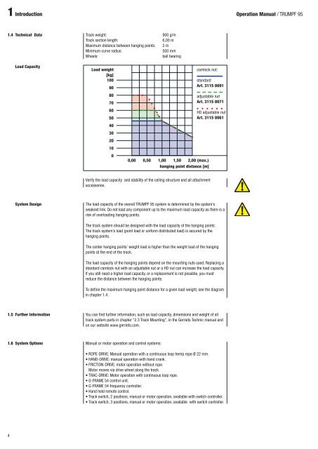
Load Capacity<br />
<strong>Track</strong> weight: 900 g/m<br />
<strong>Track</strong> section length: 6,00 m<br />
Maximum distance between hanging points: 2 m<br />
Minimum curve radius: 500 mm<br />
Wheels: ball bearing<br />
Load weight<br />
[kg]<br />
100<br />
90<br />
80<br />
70<br />
60<br />
50<br />
40<br />
30<br />
20<br />
10<br />
0<br />
Verify the load capacity and stability of the ceiling structure and all attachment<br />
accessories.<br />
<strong>System</strong> Design The load capacity of the overall <strong>TRUMPF</strong> <strong>95</strong> system is determined by the system’s<br />
weakest link. Do not load any component up to the maximum load capacity as there is a<br />
risk of overloading hanging points.<br />
The track system should be designed with the load capacity of the hanging points:<br />
The track system’s load (point load or uniform distributed load) is secured by the<br />
hanging points.<br />
The center hanging points’ weight load is higher than the weight load of the hanging<br />
points at the end of the track.<br />
The load capacity of the hanging points depend on the mounting nuts used. Replacing a<br />
standard camlock nut with an adjustable nut or a HD nut can increase the load capacity.<br />
If you still need a higher load capacity, or a replacement is not possible, you must<br />
reduce the distance between the hanging points.<br />
To define the maximum hanging point distance for a given load weight, see the diagram<br />
in chapter 1.4.<br />
You can find further information, such as load capacity, dimensions and weight of all<br />
track system parts in chapter “2.3 <strong>Track</strong> Mounting”, in the <strong>Gerriets</strong> Technic <strong>manual</strong> and<br />
on our website www.gerriets.com.<br />
Manual or motor operation and control systems:<br />
camlock nut:<br />
standard<br />
Art. 3115 0091<br />
adjustable nut<br />
Art. 3115 0071<br />
HD adjustable nut<br />
Art. 3115 0061<br />
0,00 0,50 1,00 1,50 2,00 (max.)<br />
hanging point distance [m]<br />
• ROPE-DRIVE: Manual operation with a continuous loop hemp rope Ø 22 mm.<br />
• HAND-DRIVE: <strong>manual</strong> operation with hand crank.<br />
• FRICTION-DRIVE: motor operation without rope.<br />
Motor moves via drive wheel along the track.<br />
• TRAC-DRIVE: Motor operation with continuous loop rope.<br />
• G-FRAME 54 control unit.<br />
• G-FRAME 54 frequency controller.<br />
• Hand held remote control.<br />
• <strong>Track</strong> switch, 2 positions, <strong>manual</strong> or motor operation, available with switch controller.<br />
• <strong>Track</strong> switch, 3 positions, <strong>manual</strong> or motor operation, available with switch controller.<br />
<strong>Operation</strong> Manual / <strong>TRUMPF</strong> <strong>95</strong>