F²MC-16FX FAMILY ALL SERIES MCU FLASH ... - Fujitsu
F²MC-16FX FAMILY ALL SERIES MCU FLASH ... - Fujitsu
F²MC-16FX FAMILY ALL SERIES MCU FLASH ... - Fujitsu

Create successful ePaper yourself
Turn your PDF publications into a flip-book with our unique Google optimized e-Paper software.
<strong>Fujitsu</strong> Microelectronics Europe<br />
Application Note<br />
<strong>MCU</strong>-AN-300224-E-V16<br />
<strong>F²MC</strong>-<strong>16FX</strong> <strong>FAMILY</strong><br />
16-BIT MICROCONTROLLER<br />
<strong>ALL</strong> <strong>SERIES</strong><br />
<strong>MCU</strong> <strong>FLASH</strong> PROGRAMMING<br />
AND BOOT ROM PROTOCOL<br />
APPLICATION NOTE
Revision History<br />
<strong>MCU</strong> <strong>FLASH</strong> PROGRAMMING AND BOOT ROM PROTOCOL<br />
Revision History<br />
Date Issue<br />
2006-08-22 V1.0: Fist Version; MWi<br />
2007-06-25 V1.1; Release version; MWi<br />
2007-07-17 V1.2; Corrections done, synchronous protocol added; MWi<br />
2007-07-18 V1.3; Synchronous Dial-up sequence notes added; MWi<br />
2007-10-24<br />
V1.4; update Related Documents; add supported USART of <strong>MCU</strong> Series;<br />
PHu<br />
2007-11-09 V1.5; clearify serial baudrates; PHu<br />
2007-12-05<br />
V1.6; typos corrected, checksum calculation notes to WRITE OFF command<br />
added; MWi<br />
This document contains 22 pages.<br />
<strong>MCU</strong>-AN-300224-E-V16 - 2 - © <strong>Fujitsu</strong> Microelectronics Europe GmbH
<strong>MCU</strong> <strong>FLASH</strong> PROGRAMMING AND BOOT ROM PROTOCOL<br />
Warranty and Disclaimer<br />
Warranty and Disclaimer<br />
To the maximum extent permitted by applicable law, <strong>Fujitsu</strong> Microelectronics Europe GmbH restricts<br />
its warranties and its liability for all products delivered free of charge (eg. software include or<br />
header files, application examples, target boards, evaluation boards, engineering samples of IC’s<br />
etc.), its performance and any consequential damages, on the use of the Product in accordance with<br />
(i) the terms of the License Agreement and the Sale and Purchase Agreement under which<br />
agreements the Product has been delivered, (ii) the technical descriptions and (iii) all accompanying<br />
written materials. In addition, to the maximum extent permitted by applicable law, <strong>Fujitsu</strong><br />
Microelectronics Europe GmbH disclaims all warranties and liabilities for the performance of the<br />
Product and any consequential damages in cases of unauthorised decompiling and/or reverse<br />
engineering and/or disassembling. Note, all these products are intended and must only be used<br />
in an evaluation laboratory environment.<br />
1. <strong>Fujitsu</strong> Microelectronics Europe GmbH warrants that the Product will perform substantially in<br />
accordance with the accompanying written materials for a period of 90 days form the date of<br />
receipt by the customer. Concerning the hardware components of the Product, <strong>Fujitsu</strong><br />
Microelectronics Europe GmbH warrants that the Product will be free from defects in material<br />
and workmanship under use and service as specified in the accompanying written materials<br />
for a duration of 1 year from the date of receipt by the customer.<br />
2. Should a Product turn out to be defect, <strong>Fujitsu</strong> Microelectronics Europe GmbH´s entire liability<br />
and the customer´s exclusive remedy shall be, at <strong>Fujitsu</strong> Microelectronics Europe GmbH´s<br />
sole discretion, either return of the purchase price and the license fee, or replacement of the<br />
Product or parts thereof, if the Product is returned to <strong>Fujitsu</strong> Microelectronics Europe GmbH in<br />
original packing and without further defects resulting from the customer´s use or the transport.<br />
However, this warranty is excluded if the defect has resulted from an accident not attributable<br />
to <strong>Fujitsu</strong> Microelectronics Europe GmbH, or abuse or misapplication attributable to the<br />
customer or any other third party not relating to <strong>Fujitsu</strong> Microelectronics Europe GmbH.<br />
3. To the maximum extent permitted by applicable law <strong>Fujitsu</strong> Microelectronics Europe GmbH<br />
disclaims all other warranties, whether expressed or implied, in particular, but not limited to,<br />
warranties of merchantability and fitness for a particular purpose for which the Product is not<br />
designated.<br />
4. To the maximum extent permitted by applicable law, <strong>Fujitsu</strong> Microelectronics Europe GmbH´s<br />
and its suppliers´ liability is restricted to intention and gross negligence.<br />
NO LIABILITY FOR CONSEQUENTIAL DAMAGES<br />
To the maximum extent permitted by applicable law, in no event shall <strong>Fujitsu</strong><br />
Microelectronics Europe GmbH and its suppliers be liable for any damages whatsoever<br />
(including but without limitation, consequential and/or indirect damages for personal<br />
injury, assets of substantial value, loss of profits, interruption of business operation,<br />
loss of information, or any other monetary or pecuniary loss) arising from the use of<br />
the Product.<br />
Should one of the above stipulations be or become invalid and/or unenforceable, the remaining<br />
stipulations shall stay in full effect<br />
© <strong>Fujitsu</strong> Microelectronics Europe GmbH - 3 - <strong>MCU</strong>-AN-300224-E-V16
Contents<br />
<strong>MCU</strong> <strong>FLASH</strong> PROGRAMMING AND BOOT ROM PROTOCOL<br />
Contents<br />
REVISION HISTORY............................................................................................................ 2<br />
WARRANTY AND DISCLAIMER ......................................................................................... 3<br />
CONTENTS .......................................................................................................................... 4<br />
1 INTRODUCTION.............................................................................................................. 6<br />
2 <strong>MCU</strong> CONNECTION ........................................................................................................ 7<br />
2.1 Serial Interface ........................................................................................................ 7<br />
3 USING FUJITSU STARTER KITS ................................................................................... 8<br />
3.1 Starter Kits .............................................................................................................. 8<br />
3.1.1 <strong>FLASH</strong>-CAN-100P-340 V1.1, V2.0 ............................................................ 8<br />
3.1.1.1 Jumpers..................................................................................... 8<br />
3.1.1.2 Mode Pins (S2) .......................................................................... 8<br />
3.1.2 SK-96380-120PMT V1.0............................................................................ 9<br />
3.1.2.1 Mode Pins (S1) .......................................................................... 9<br />
4 FUJITSU F 2 MC-<strong>16FX</strong> <strong>FLASH</strong> PROGRAMMER............................................................. 10<br />
4.1 Introduction ........................................................................................................... 10<br />
4.2 Usage.................................................................................................................... 10<br />
5 EXTERNAL CLOCK FREQUENCIES AND BAUD RATES ........................................... 12<br />
5.1 External Clock ....................................................................................................... 12<br />
5.2 Asynchronous Baud Rate Configuration Tables .................................................... 12<br />
5.2.1 MB96F32x/MB96F34x/MB96F35x/MB96F38x ......................................... 12<br />
6 <strong>FLASH</strong> <strong>MCU</strong> BOOT ROM PROTOCOL......................................................................... 13<br />
6.1 Introduction ........................................................................................................... 13<br />
6.2 Boot ROM Sequence for asynchronous (Duplex) Communication......................... 14<br />
6.2.1 Connection .............................................................................................. 15<br />
6.2.2 Calibrate off ............................................................................................. 15<br />
6.2.3 Check Flash Security............................................................................... 16<br />
6.2.4 Locking Flash Memory............................................................................. 16<br />
6.2.5 Download Kernel ..................................................................................... 17<br />
6.2.6 Run (Jump to RAM) ................................................................................. 17<br />
6.2.7 Checksum................................................................................................ 17<br />
6.3 Boot ROM Sequence for Synchronous (Duplex) Communication .......................... 18<br />
6.3.1 Synchronous Communication Preface..................................................... 18<br />
6.3.2 Boot ROM Sequence for Synchronous (Duplex) Communication ............ 19<br />
<strong>MCU</strong>-AN-300224-E-V16 - 4 - © <strong>Fujitsu</strong> Microelectronics Europe GmbH
<strong>MCU</strong> <strong>FLASH</strong> PROGRAMMING AND BOOT ROM PROTOCOL<br />
Contents<br />
6.3.3 Connection .............................................................................................. 19<br />
6.3.4 Command Sequences ............................................................................. 20<br />
7 SERIAL PROGRAMMING USART ................................................................................ 21<br />
8 APPENDIX..................................................................................................................... 22<br />
8.1 Related Documents............................................................................................... 22<br />
© <strong>Fujitsu</strong> Microelectronics Europe GmbH - 5 - <strong>MCU</strong>-AN-300224-E-V16
1 Introduction<br />
<strong>MCU</strong> <strong>FLASH</strong> PROGRAMMING AND BOOT ROM PROTOCOL<br />
Chapter 1 Introduction<br />
This application note describes how to program a <strong>16FX</strong> <strong>MCU</strong> with the serial interface and<br />
shows the Boot ROM communication protocol, so that the user can create his own<br />
programmer software.<br />
<strong>MCU</strong>-AN-300224-E-V16 - 6 - © <strong>Fujitsu</strong> Microelectronics Europe GmbH
2 <strong>MCU</strong> Connection<br />
<strong>MCU</strong> <strong>FLASH</strong> PROGRAMMING AND BOOT ROM PROTOCOL<br />
Chapter 2 <strong>MCU</strong> Connection<br />
THE CONNECTION TO THE <strong>MCU</strong><br />
2.1 Serial Interface<br />
For <strong>MCU</strong> Flash Programming a serial interface (USART) is used. The embedded Boot ROM<br />
allows the user to program the <strong>MCU</strong> in asynchronous and synchronous serial<br />
communication. The <strong>MCU</strong> has to be switched to its embedded Boot ROM serial<br />
programming mode for this.<br />
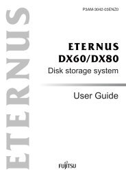
The asynchronous programming can be done by a standard PC COM interface. The<br />
following Block Diagram shows how to connect a PC to a <strong>16FX</strong> <strong>MCU</strong>.<br />
PC<br />
TX<br />
RX<br />
SCLK*<br />
Level<br />
Shifter<br />
(RS232 ↔<br />
3 …5.5 V)<br />
Open: Run Mode<br />
Closed: Flash<br />
Programming Mode<br />
Figure 2-1: Flash Programming Connection Block Diagram<br />
SINn<br />
SOTn<br />
SCKn<br />
MD0<br />
MD1<br />
MD2<br />
RSTX<br />
<strong>MCU</strong><br />
*optional<br />
Please see application note AN-390223-<strong>16FX</strong>_HW_SETUP for details of a minimum <strong>MCU</strong> system<br />
and hardware recommendations.<br />
Multiple USARTs are usable for serial Flash programming. The Boot ROM scans the<br />
USARTs after Reset in serial Flash programming mode and tries to establish<br />
communication. See Datasheet for device specific USART channels. In most cases USART0<br />
to USART3 are supported.<br />
© <strong>Fujitsu</strong> Microelectronics Europe GmbH - 7 - <strong>MCU</strong>-AN-300224-E-V16
<strong>MCU</strong> <strong>FLASH</strong> PROGRAMMING AND BOOT ROM PROTOCOL<br />
Chapter 3 Using <strong>Fujitsu</strong> Starter Kits<br />
3 Using <strong>Fujitsu</strong> Starter Kits<br />
JUMPER SETTINGS OF FUJITSU STARTER KIT BOARDS<br />
3.1 Starter Kits<br />
For almost each <strong>16FX</strong> device a <strong>Fujitsu</strong> Starter Kit board exists. These boards have at least<br />
one connecter to a USART of the supported <strong>MCU</strong>. The following tables shows, how to<br />
configure the jumpers and set the mode pins of several boards for serial Flash Programming<br />
communication.<br />
3.1.1 <strong>FLASH</strong>-CAN-100P-340 V1.1, V2.0<br />
This board is applicable for the MB96F34x series in QFP-100 package.<br />
3.1.1.1 Jumpers<br />
Jumper USART0 USART2<br />
JP1a closed x<br />
JP1b open x<br />
JP1c open x<br />
JP2a closed x<br />
JP2b open x<br />
JP2c open x<br />
JP44 closed x<br />
JP31* open x<br />
JP8a x closed<br />
JP8b x open<br />
JP8c x open<br />
JP6a x closed<br />
JP6b x open<br />
JP6c x open<br />
JP32* x open<br />
* When not using RTS/CTS for <strong>MCU</strong>-Reset<br />
3.1.1.2 Mode Pins (S2)<br />
Operation Mode 1 2 3 4 5 6 7 8<br />
Normal Run OFF OFF ON x x x x x<br />
Flash Programming ON OFF ON x x x x x<br />
<strong>MCU</strong>-AN-300224-E-V16 - 8 - © <strong>Fujitsu</strong> Microelectronics Europe GmbH
<strong>MCU</strong> <strong>FLASH</strong> PROGRAMMING AND BOOT ROM PROTOCOL<br />
Chapter 3 Using <strong>Fujitsu</strong> Starter Kits<br />
3.1.2 SK-96380-120PMT V1.0<br />
This board is applicable for the MB96F38x series in LQFP-120 package.<br />
Jumper USART0 USART2<br />
JP21 1-2 x<br />
JP23* open x<br />
JP25 1-2 x<br />
JP27 1-2 x<br />
JP28 open x<br />
JP37 x 1-2<br />
JP38* x open<br />
JP39 x 1-2<br />
JP40 x 1-2<br />
JP42 x open<br />
JP33* open open<br />
* When not using RTS/CTS for <strong>MCU</strong>-Reset<br />
3.1.2.1 Mode Pins (S1)<br />
Operation Mode 1 2 3 4<br />
Normal Run OFF OFF ON x<br />
Flash Programming ON OFF ON x<br />
© <strong>Fujitsu</strong> Microelectronics Europe GmbH - 9 - <strong>MCU</strong>-AN-300224-E-V16
<strong>MCU</strong> <strong>FLASH</strong> PROGRAMMING AND BOOT ROM PROTOCOL<br />
Chapter 4 <strong>Fujitsu</strong> F2MC-<strong>16FX</strong> Flash Programmer<br />
4 <strong>Fujitsu</strong> F 2 MC-<strong>16FX</strong> Flash Programmer<br />
HOW TO USE THE F 2 MC-<strong>16FX</strong> <strong>FLASH</strong> PROGRAMMER<br />
4.1 Introduction<br />
The <strong>Fujitsu</strong> F 2 MC-<strong>16FX</strong> Flash Programmer is a freeware tool for programming <strong>16FX</strong> Flash<br />
<strong>MCU</strong>. It uses standard COM (RS232) communication ports of the PC.<br />
Please note, that the F 2 MC-<strong>16FX</strong> Flash Programmer Software is for developing and evaluation<br />
purposes only – it is not approved for mass production.<br />
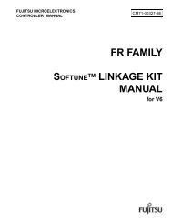
4.2 Usage<br />
After starting the Flash Programmer its user interface will look like the following:<br />
5a<br />
2<br />
3<br />
4<br />
5b 5b (5b)<br />
5b<br />
MB96F348H/T<br />
The programming is done by a programming kernel, which is downloaded to the RAM of the<br />
<strong>MCU</strong> by the embedded Boot ROM. This kernel performs the further steps of the<br />
programming and communicates with the PC. This is described in more detail in chapter 6.<br />
For programming a Flash <strong>MCU</strong> the user should proceed as follows.<br />
1. Set the <strong>MCU</strong> to Flash programming mode (3) and perform a Reset.<br />
2. Select “Target Microcontroller” to choose the <strong>MCU</strong>.<br />
3. Enter used Crystal Frequency on the target board.<br />
4. Browse to the Hex-File (project_name.mhx) of the project.<br />
At this step the user has two different possibilities to proceed.<br />
5a. Full Operation: This performs all steps for programming the <strong>MCU</strong>. It includes<br />
“Download”, “Erase”, “Blank Check”, and “Program & Verify”.<br />
5b. Single Steps: “Download”, “Erase” (“Blank Check” optionally), and “Program & Verify”<br />
manually.<br />
<strong>MCU</strong>-AN-300224-E-V16 - 10 - © <strong>Fujitsu</strong> Microelectronics Europe GmbH
<strong>MCU</strong> <strong>FLASH</strong> PROGRAMMING AND BOOT ROM PROTOCOL<br />
Chapter 4 <strong>Fujitsu</strong> F2MC-<strong>16FX</strong> Flash Programmer<br />
A chip erase command is performed regardless of using method of 5a or 5b.<br />
After successful programming, the <strong>MCU</strong> should be switched to normal RUN mode via the<br />
mode pins (3) and a reset will start the programmed software.<br />
With “Set Environment” several settings can be done. The most important is the options for<br />
COM port selection.<br />
© <strong>Fujitsu</strong> Microelectronics Europe GmbH - 11 - <strong>MCU</strong>-AN-300224-E-V16
<strong>MCU</strong> <strong>FLASH</strong> PROGRAMMING AND BOOT ROM PROTOCOL<br />
Chapter 5 External Clock Frequencies and Baud Rates<br />
5 External Clock Frequencies and Baud Rates<br />
CONFIGURATION OF CLOCK FREQUENCY AND COMMUNICATION BAUD RATE<br />
5.1 External Clock<br />
Using a <strong>16FX</strong> <strong>MCU</strong> the used baud rate for serial Flash Programming can vary in a wide<br />
range by using a fix external clock frequency. The Boot ROM uses a protocol, which<br />
measures the incoming baud rate and adjusts its own with it.<br />
Without external clock, Boot ROM uses the internal RC clock.<br />
5.2 Asynchronous Baud Rate Configuration Tables<br />
The following table gives an overview of several baud rate ranges for several external<br />
frequencies depending on the used <strong>MCU</strong>. The shown baud rates are used only for<br />
establishing the communication. Further communication may use higher baud rates. This<br />
depends on the user application.<br />
5.2.1 MB96F32x/MB96F34x/MB96F35x/MB96F38x<br />
External Minimum Baud Maximum Baud<br />
Frequency Rate<br />
Rate<br />
3.5 MHz 4800 19200<br />
4 MHz 4800 38400<br />
5 MHz 4800 38400<br />
6 MHz 4800 38400<br />
8 MHz 9600 76800<br />
10 MHz 9600 115200<br />
12 MHz 9600 115200<br />
16 MHz 19200 153600<br />
<strong>MCU</strong>-AN-300224-E-V16 - 12 - © <strong>Fujitsu</strong> Microelectronics Europe GmbH
<strong>MCU</strong> <strong>FLASH</strong> PROGRAMMING AND BOOT ROM PROTOCOL<br />
Chapter 6 Flash <strong>MCU</strong> Boot ROM Protocol<br />
6 Flash <strong>MCU</strong> Boot ROM Protocol<br />
SERIAL COMMUNICATION TO PROGRAM <strong>FLASH</strong> MEMORY<br />
6.1 Introduction<br />
The <strong>16FX</strong> Flash <strong>MCU</strong>s contain a fixed firmware (Boot ROM) program that supports a<br />
proprietary protocol to allow download of a user program (kernel) to on-chip RAM memory<br />
(Figure 6-1).<br />
PC serial Data<br />
Figure 6-1: Download of User Program to RAM<br />
The user program is then able to manipulate the on-chip Flash Memory as required (Figure<br />
6-2). It communicates directly via the USART to the connected PC, which sends the<br />
commands.<br />
PC serial Data<br />
USART<br />
USART<br />
Boot<br />
ROM<br />
Flash<br />
Memory<br />
Boot<br />
ROM<br />
Flash<br />
Memory<br />
RAM<br />
RAM<br />
Figure 6-2: Programming Flash Memory from RAM<br />
© <strong>Fujitsu</strong> Microelectronics Europe GmbH - 13 - <strong>MCU</strong>-AN-300224-E-V16
<strong>MCU</strong> <strong>FLASH</strong> PROGRAMMING AND BOOT ROM PROTOCOL<br />
Chapter 6 Flash <strong>MCU</strong> Boot ROM Protocol<br />
The Boot ROM supports asynchronous (Duplex and K-Line) and synchronous serial<br />
communication. Except the auto calibration phase for the asynchronous mode(s) at the<br />
beginning, the ROM protocol is identical for both communication types.<br />
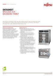
6.2 Boot ROM Sequence for asynchronous (Duplex) Communication<br />
The following flow chart shows the communication from a PC to the Boot ROM. Please note,<br />
that the data format is 8N2 for PC and 8N1 for <strong>MCU</strong>, when using asynchronous<br />
communication. For the baud rate to use, please refer to chapter 5.2.<br />
Reset<br />
Connect<br />
Calibrate off<br />
Check Flash Security<br />
Forbidden?<br />
N<br />
Download<br />
Kernel<br />
Run<br />
(Jump to RAM)<br />
Y<br />
Lock Sat Flash /<br />
Lock Main Flash<br />
The PC has to send 8N2 format at “connect” and <strong>MCU</strong> sends back 8N1 format. The PC can<br />
switch to 8N1 then, if there are problems receiving 8N1 format.<br />
If the Flash Memory is secured, the user program (Kernel) should perform a chip erase and<br />
then await an external Reset. After this a new connection is performed. This is also the<br />
procedure using the <strong>Fujitsu</strong> Flash Programmer software.<br />
<strong>MCU</strong>-AN-300224-E-V16 - 14 - © <strong>Fujitsu</strong> Microelectronics Europe GmbH
<strong>MCU</strong> <strong>FLASH</strong> PROGRAMMING AND BOOT ROM PROTOCOL<br />
Chapter 6 Flash <strong>MCU</strong> Boot ROM Protocol<br />
6.2.1 Connection<br />
In the connection phase the PC sends a sequence to the <strong>MCU</strong>. This sequence should use<br />
the following data.<br />
Calibration Header Dial-up Pattern<br />
Synch Synch Dial-up Dial-up Dial-up<br />
Break Byte ID 0 ID 1 ID 2<br />
0x00 0x55 0x66<br />
PC → <strong>MCU</strong><br />
0x77 0x88<br />
If the connection was successful, the <strong>MCU</strong> set its USART-SOT pin from Hi-Z to “1” and<br />
sends a response byte:<br />
Response<br />
0x46<br />
<strong>MCU</strong> → PC<br />
Note: Until 32 bit times before 0x46 is sent by <strong>MCU</strong>, PC may receive random data.<br />
<strong>MCU</strong> RX<br />
<strong>MCU</strong> TX<br />
Dial-up command<br />
Dial-up command echo or noise<br />
Figure 6-3: Example of asynchronous dial-up command, command echo (intermediate framing error) and<br />
final response code<br />
6.2.2 Calibrate off<br />
On crystal systems the calibration header is not needed for each command, so the<br />
calibration header can be switched off. The switch off command itself has to be sent with the<br />
calibration header of course.<br />
Calibration Header Header Payload<br />
Synch<br />
Break<br />
Synch<br />
Byte<br />
Calibrate off<br />
Command<br />
Mode 0<br />
Checksum<br />
0x00 0x55 0x87<br />
PC → <strong>MCU</strong><br />
0x00 0x78<br />
The <strong>MCU</strong> sends back a response byte.<br />
Response<br />
0x69<br />
<strong>MCU</strong> → PC<br />
Dial-up response frame<br />
© <strong>Fujitsu</strong> Microelectronics Europe GmbH - 15 - <strong>MCU</strong>-AN-300224-E-V16
6.2.3 Check Flash Security<br />
<strong>MCU</strong> <strong>FLASH</strong> PROGRAMMING AND BOOT ROM PROTOCOL<br />
Chapter 6 Flash <strong>MCU</strong> Boot ROM Protocol<br />
The Flash Security is read by the READ8 command to dummy address 0xFF0000.<br />
Cmd Addr0<br />
Header<br />
Addr1 Addr2 Count<br />
Checksum<br />
0x90 0x00 0x00 0xFF 0x01 0x6E<br />
PC → <strong>MCU</strong><br />
If the Flash memory is secured (“Forbidden”), the response of the <strong>MCU</strong> will be:<br />
In the unsecured case, the response will be:<br />
Response<br />
0x96<br />
<strong>MCU</strong> → PC<br />
Header<br />
Response<br />
Payload<br />
Data<br />
Checksum<br />
0x69 0xXX<br />
PC → <strong>MCU</strong><br />
0xYY<br />
Please note that 0xXX represents the (random) content of the Flash address 0xFF0000 and<br />
0xYY the accordant checksum.<br />
For further details please refer to application note mcu-an-300213-e-16fx_flash_security.<br />
6.2.4 Locking Flash Memory<br />
In case of secured Flash memory every memory command is forbidden. The PC has to send<br />
the LOCK command to allow read and write access to RAM. The flash memory reading is not<br />
possible by hardware. Once the Flash memory is locked, the contents cannot be unlocked<br />
anymore. However, instead of LOCK, the UNLOCK (0x0A) command grants access to Flash,<br />
if the key is correct.<br />
Header<br />
Cmd Select<br />
Checksum<br />
0x0C 0xFF<br />
PC → <strong>MCU</strong><br />
0xYY<br />
The command is accepted, if the <strong>MCU</strong> sends the following response:<br />
Response<br />
0x69<br />
<strong>MCU</strong> → PC<br />
<strong>MCU</strong>-AN-300224-E-V16 - 16 - © <strong>Fujitsu</strong> Microelectronics Europe GmbH
6.2.5 Download Kernel<br />
<strong>MCU</strong> <strong>FLASH</strong> PROGRAMMING AND BOOT ROM PROTOCOL<br />
Chapter 6 Flash <strong>MCU</strong> Boot ROM Protocol<br />
The Kernel is downloaded by the WRITE OFF command to the <strong>MCU</strong> RAM. The start<br />
address depends on the size of the device RAM. Please see the datasheet for details. By<br />
default it should be start at the upper 2K bytes of the RAM: 0x007A20.<br />
Cmd Addr0<br />
Header<br />
Addr1 Addr2<br />
Payload<br />
Count<br />
N<br />
Premature<br />
Checksum<br />
Data0 . . . Data N-1<br />
Checksum<br />
0x12 0xXX 0xYY 0x00 0xZZ 0xTT 0xUU ... 0xVV 0xWW<br />
PC → <strong>MCU</strong><br />
Note that the payload (N) can contain a maximum of 256 bytes. In this case Count N has to<br />
be set to 0x00.<br />
Note that the checksum (0xWW) is calculated over all bytes of the WRITE OFF command and<br />
the premature checksum (0xTT) is calculated over the 4 previous header bytes only.<br />
Also note that the checksum (0xWW) can also be calculated over only the payload bytes, but<br />
starting with 0xFF as initial value.<br />
In case of no errors the <strong>MCU</strong> will respond with the usual single byte response:<br />
Response<br />
0x69<br />
<strong>MCU</strong> → PC<br />
6.2.6 Run (Jump to RAM)<br />
After downloading the kernel, it can be executed by the RUN command.<br />
Header<br />
Cmd Addr0<br />
Payload<br />
Addr1 Addr2<br />
Checksum<br />
0x9F 0xXX 0xYY<br />
PC → <strong>MCU</strong><br />
0xZZ 0xWW<br />
The <strong>MCU</strong> responds with the usual single byte response before performing the jump to the<br />
denoted address.<br />
Response<br />
0x69<br />
<strong>MCU</strong> → PC<br />
6.2.7 Checksum<br />
The checksum is calculated with the following equation. It includes all bytes (n) except the<br />
calibration header (0x00, 0x55):<br />
⎛<br />
Checksum = 0xFF<br />
− ⎜<br />
⎝<br />
n<br />
∑<br />
i=<br />
1<br />
n<br />
n<br />
⎢ ⎥ ⎢ ⎥<br />
⎢∑<br />
datai<br />
⎥ ⎢∑<br />
datai<br />
⎞<br />
⎥<br />
i=<br />
1<br />
i=<br />
1<br />
data ⎟ − ⎢ ⎥ − ⎢ ⎥<br />
i mod 0x100<br />
⎠<br />
⎢ 0x100<br />
⎥ ⎢0x10000⎥<br />
⎢<br />
⎣<br />
⎥<br />
⎦<br />
⎢<br />
⎣<br />
⎥<br />
⎦<br />
The last two summands are correction values, if the overall sum crosses each 0x100<br />
boundary and the 0x10000 boundary.<br />
© <strong>Fujitsu</strong> Microelectronics Europe GmbH - 17 - <strong>MCU</strong>-AN-300224-E-V16
<strong>MCU</strong> <strong>FLASH</strong> PROGRAMMING AND BOOT ROM PROTOCOL<br />
Chapter 6 Flash <strong>MCU</strong> Boot ROM Protocol<br />
6.3 Boot ROM Sequence for Synchronous (Duplex) Communication<br />
6.3.1 Synchronous Communication Preface<br />
A synchronous connection uses common timing by common clock but separate media. The<br />
clock is mastered by client. An active clock shifts bytes to both, up stream and down stream.<br />
If the client is not capable of mastering the connection, an interface converter has to be<br />
used.<br />
Up<br />
TX<br />
RX<br />
Client (PC) IF<br />
CLK Server (<strong>MCU</strong>)<br />
RX<br />
Down<br />
TX<br />
Figure 6-4: Separated synchronous up/down stream wires<br />
In order to receive the response from server (clock slave), the client (clock master) needs to<br />
send dummy bytes according to the expected number of response bytes. Vice versa, the<br />
server (<strong>MCU</strong>) will send dummy bytes (NULL), when it receives the command frame. The<br />
client needs to consider the reception of those dummy bytes. If the server does not explicitly<br />
send command dummy and response frame, the client receives random data.<br />
Up<br />
IF TX � <strong>MCU</strong> RX<br />
Down<br />
<strong>MCU</strong> TX � IF RX<br />
Command Frame<br />
Figure 6-5: Separated synchronous up/down stream wires<br />
A client, which uses an asynchronous-to-synchronous converter, also needs to consider<br />
delayed reception. Command dummy and response will be delayed due to converter and<br />
different throughput on busses.<br />
Client Up<br />
PC TX� IF RX<br />
Client Down<br />
IF TX � PC RX<br />
Command Dummy<br />
Command Frame<br />
Command Dummy<br />
Figure 6-6: Delayed Command Dummy of interface converter<br />
Response Dummy<br />
time<br />
Resonse Frame<br />
Response Dummy<br />
time<br />
Response Frame<br />
Since the start-up performance of the <strong>MCU</strong> is limited by slow system clock, the throughput of<br />
synchronous connection must be limited too. Instead of sending continuous bytes, a byte<br />
cycle time is applied (e.g. by interface converter). It might be dynamically adapted to the<br />
frequency of core bus clock CLKB. However, during dial-up, a worst-case default shall be<br />
used.<br />
The byte cycle time is also sufficient to separate command frame and response dummy.<br />
<strong>MCU</strong>-AN-300224-E-V16 - 18 - © <strong>Fujitsu</strong> Microelectronics Europe GmbH
Up<br />
IF TX� <strong>MCU</strong> RX<br />
<strong>MCU</strong> <strong>FLASH</strong> PROGRAMMING AND BOOT ROM PROTOCOL<br />
Chapter 6 Flash <strong>MCU</strong> Boot ROM Protocol<br />
Command Frame Response Dummy<br />
... ...<br />
byte cycle time byte cycle time<br />
Figure 6-7: byte-cycle-time-wise transmission of synchronous frames<br />
Note, that the minimum byte cycle time should not be less than the minimum asynchronous<br />
data frame time after dial-up connection. During Dial-up the byte cycle time should be<br />
between 1.5 ms and 2.5 ms.<br />
6.3.2 Boot ROM Sequence for Synchronous (Duplex) Communication<br />
The sequence is the same described for asynchronous communication (6.2).<br />
6.3.3 Connection<br />
In the connection phase the PC sends a sequence to the <strong>MCU</strong>. This sequence should use<br />
the following data. It is the same pattern like in asynchronous communication but without<br />
0x00 and 0x55 data at the beginning.<br />
Dial-up Pattern<br />
Dial-up Dial-up Dial-up<br />
ID 0 ID 1 ID 2<br />
0x66 0x77<br />
PC → <strong>MCU</strong><br />
0x88<br />
If the connection was successful, the <strong>MCU</strong> sends a response byte. Please be aware, that for<br />
any response the PC has to send a dummy byte.<br />
Response<br />
0x46<br />
<strong>MCU</strong> → PC<br />
byte cycle time<br />
Note: At any dial-up data byte sent by the PC before 0x46 is responded by <strong>MCU</strong>, PC may<br />
receive random data.<br />
© <strong>Fujitsu</strong> Microelectronics Europe GmbH - 19 - <strong>MCU</strong>-AN-300224-E-V16<br />
time
<strong>MCU</strong> RX<br />
CLK<br />
<strong>MCU</strong> TX<br />
Up<br />
Down<br />
<strong>MCU</strong> <strong>FLASH</strong> PROGRAMMING AND BOOT ROM PROTOCOL<br />
Chapter 6 Flash <strong>MCU</strong> Boot ROM Protocol<br />
Figure 6-8: Example of synchronous dial-up<br />
Note, that the byte cycle time during dial-up command should be between 1.5 ms and 2.5<br />
ms unless of the used baud rate. After successful connection the byte cycle time can be<br />
shorter but should not undercut the minimum frame time of the maximum (asynchronous)<br />
baud rate.<br />
<strong>MCU</strong> RX<br />
CLK<br />
<strong>MCU</strong> TX<br />
Up<br />
Down<br />
Dial-up command<br />
Dial-up command R. Second command<br />
1.5 ms ... 2.5 ms<br />
byte cycle time<br />
Figure 6-9: Example of byte cycle times<br />
Dial-up<br />
response<br />
dummy<br />
Dial-up response echo or noise Dial-up response frame<br />
Shorter byte cycle time<br />
6.3.4 Command Sequences<br />
The command sequences are the same like for asynchronous communication. Please refer<br />
to the descriptions above (start from 6.2.2).<br />
<strong>MCU</strong>-AN-300224-E-V16 - 20 - © <strong>Fujitsu</strong> Microelectronics Europe GmbH
<strong>MCU</strong> <strong>FLASH</strong> PROGRAMMING AND BOOT ROM PROTOCOL<br />
Chapter 7 Serial Programming USART<br />
7 Serial Programming USART<br />
This sections shows the USARTs supported for serial communication mode<br />
For each <strong>16FX</strong> <strong>MCU</strong> series, one of up to 4 USARTs can be used to establish a connection in<br />
serial communication mode. Sometmes, a USART is offered on different pins, the default<br />
one and the relocated one. The relocated ones show the suffix R at the pin names. Example:<br />
USART 2 uses pins SIN2, SOT2, and SCK2. When relocation is enabled, the pins SIN2_R,<br />
SOT2_R, and SCK2_R are used. Please note that relocated USARTs will be shown<br />
separately.<br />
Series USART<br />
MB96320 2, 3, 7R, 8R<br />
MB96340 0, 1, 2, 3<br />
MB96350 2, 3, 7R, 8R<br />
MB96380 0, 1, 2<br />
© <strong>Fujitsu</strong> Microelectronics Europe GmbH - 21 - <strong>MCU</strong>-AN-300224-E-V16
8 Appendix<br />
FURTHER INFORMATION<br />
8.1 Related Documents<br />
<strong>MCU</strong> <strong>FLASH</strong> PROGRAMMING AND BOOT ROM PROTOCOL<br />
Chapter 8 Appendix<br />
mcu-an-300213-e-16fx_flash_security<br />
This application note shows the Flash Security mechanism.<br />
mcu-an-300218-e-16fx_flash<br />
This application note shows the architecture of the Flash memory and how to<br />
program it.<br />
mcu-an-300223-e-16fx_hw_setup<br />
This application note describes a minimum <strong>16FX</strong> hardware system and gives further<br />
hardware design recommendations.<br />
<strong>MCU</strong>-AN-300224-E-V16 - 22 - © <strong>Fujitsu</strong> Microelectronics Europe GmbH