MN4GA/4GB Series - Romicon
MN4GA/4GB Series - Romicon
MN4GA/4GB Series - Romicon
- TAGS
- series
- romicon
- www.romicon.nl

You also want an ePaper? Increase the reach of your titles
YUMPU automatically turns print PDFs into web optimized ePapers that Google loves.
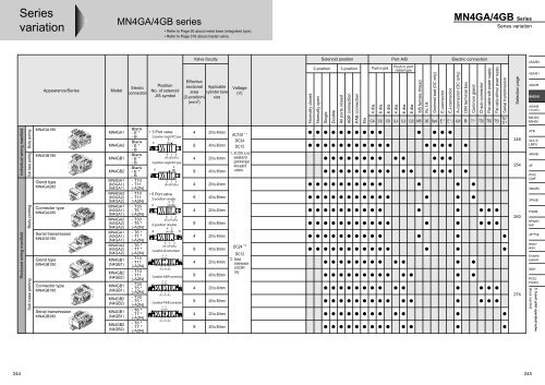
<strong>Series</strong><br />
variation<br />
Individual wiring manifold<br />
Reduced wiring manifold<br />
Body porting<br />
Sub base porting<br />
Body porting<br />
Sub base porting<br />
Appearance/<strong>Series</strong><br />
<strong>MN4GA</strong>180<br />
MN<strong>4GB</strong>180<br />
Gland type<br />
<strong>MN4GA</strong>280<br />
Connector type<br />
<strong>MN4GA</strong>280<br />
Serial transmission<br />
<strong>MN4GA</strong>180<br />
Gland type<br />
MN<strong>4GB</strong>180<br />
Connector type<br />
MN<strong>4GB</strong>180<br />
Serial transmission<br />
MN<strong>4GB</strong>280<br />
Model<br />
<strong>MN4GA</strong>1<br />
<strong>MN4GA</strong>2<br />
MN<strong>4GB</strong>1<br />
MN<strong>4GB</strong>2<br />
<strong>MN4GA</strong>1<br />
(N3GA1)<br />
(N4GA1)<br />
<strong>MN4GA</strong>2<br />
(N3GA2)<br />
(N4GA2)<br />
<strong>MN4GA</strong>1<br />
(N3GA1)<br />
(N4GA1)<br />
<strong>MN4GA</strong>2<br />
(N3GA2)<br />
(N4GA2)<br />
<strong>MN4GA</strong>1<br />
(N3GA1)<br />
(N4GA1)<br />
<strong>MN4GA</strong>2<br />
(N3GA2)<br />
(N4GA2)<br />
MN<strong>4GB</strong>1<br />
(N<strong>4GB</strong>1)<br />
MN<strong>4GB</strong>2<br />
(N<strong>4GB</strong>2)<br />
MN<strong>4GB</strong>1<br />
(N<strong>4GB</strong>1)<br />
MN<strong>4GB</strong>2<br />
(N<strong>4GB</strong>2)<br />
MN<strong>4GB</strong>1<br />
(N<strong>4GB</strong>1)<br />
MN<strong>4GB</strong>2<br />
(N<strong>4GB</strong>2)<br />
<strong>MN4GA</strong>/<strong>4GB</strong> series<br />
Electric<br />
connection<br />
Blank<br />
- E *<br />
- B<br />
Blank<br />
- E *<br />
- B<br />
Blank<br />
- E *<br />
- B<br />
Blank<br />
- E *<br />
- B<br />
- T10<br />
- T11<br />
(-A2N)<br />
- T10<br />
- T11<br />
(-A2N)<br />
- T30<br />
- T5 *<br />
(-A2N)<br />
- T30<br />
- T5 *<br />
(-A2N)<br />
- T6 *<br />
- T7 *<br />
(-A2N)<br />
- T6 *<br />
- T7 *<br />
(-A2N)<br />
- T10<br />
- T11<br />
(-A2N)<br />
- T10<br />
- T11<br />
(-A2N)<br />
- T30<br />
- T5 *<br />
(-A2N)<br />
- T30<br />
- T5 *<br />
(-A2N)<br />
- T6 *<br />
- T7 *<br />
(-A2N)<br />
- T6 *<br />
- T7 *<br />
(-A2N)<br />
• Refer to Page 90 about metal base (integrated type).<br />
• Refer to Page 316 about master valve.<br />
Position<br />
No. of solenoid<br />
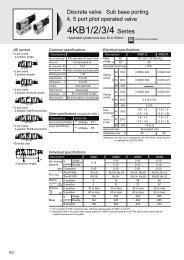
JIS symbol<br />
• 3 Port valve<br />
2-position single NC type<br />
a<br />
4<br />
(A)<br />
5 1 3<br />
(R1) (P) (R2)<br />
2-position single NO type<br />
a<br />
2<br />
(B)<br />
5 1 3<br />
(R1) (P) (R2)<br />
• 5 Port valve<br />
2-position single<br />
4 2<br />
a (A) (B)<br />
5 1 3<br />
(R1) (P) (R2)<br />
2-position double<br />
a<br />
4 2<br />
(A) (B) b<br />
5 1 3<br />
(R1) (P) (R2)<br />
3-position all ports closed<br />
4 2<br />
a<br />
(A) (B)<br />
b<br />
5 1 3<br />
(R1) (P) (R2)<br />
3-position A/B/R connection<br />
4 2<br />
a<br />
(A) (B)<br />
b<br />
5 1 3<br />
(R1) (P) (R2)<br />
3-position P/A/B connection<br />
4 2<br />
(A) (B)<br />
a b<br />
5 1 3<br />
(R1) (P) (R2)<br />
Valve faculty<br />
Effective<br />
sectional<br />
area<br />
(2-position)<br />
(mm2 Applicable<br />
cylinder bore<br />
size<br />
)<br />
4<br />
9<br />
4<br />
9<br />
4<br />
9<br />
4<br />
9<br />
4<br />
9<br />
4<br />
9<br />
4<br />
9<br />
4<br />
9<br />
20 to 40mm<br />
40 to 80mm<br />
20 to 40mm<br />
40 to 80mm<br />
20 to 40mm<br />
40 to 80mm<br />
20 to 40mm<br />
40 to 80mm<br />
20 to 40mm<br />
40 to 80mm<br />
20 to 40mm<br />
40 to 80mm<br />
20 to 40mm<br />
40 to 80mm<br />
20 to 40mm<br />
40 to 80mm<br />
Voltage<br />
(V)<br />
AC100 * 1<br />
DC24<br />
DC12<br />
*1. AC100V is not<br />
available for<br />
grommet lead<br />
wire specifi<br />
-cations.<br />
* 2<br />
DC24<br />
DC12<br />
*2. Serial<br />
transmission<br />
is DC24V<br />
only.<br />
Solenoid position Port A/B Electric connection<br />
244 245<br />
Normally closed<br />
2-position 3-position<br />
Normally open<br />
Single<br />
Double<br />
All ports closed<br />
ABR connection<br />
PAB connection<br />
Mix<br />
Push in joint<br />
4 dia.<br />
6 dia.<br />
8 dia.<br />
Push in joint<br />
radial type<br />
4 dia.<br />
6 dia.<br />
8 dia.<br />
M5 female thread<br />
Rc 1/8<br />
Grommet lead (DC only)<br />
C4 C6 C8 CL4 CL6 CL8 M5 06 Blank E * E * J A2N B T1 * T30 T50 T51<br />
E-connector<br />
EJ-connector<br />
<strong>MN4GA</strong>/<strong>4GB</strong> <strong>Series</strong><br />
<strong>Series</strong> variation<br />
A-connector (DC only)<br />
DIN terminal box<br />
Common gland<br />
D-sub connector<br />
Flat cable with power supply<br />
Flat cable without power supply<br />
Serial transmission<br />
T6 *<br />
T7 *<br />
Selection page<br />
248<br />
254<br />
260<br />
274<br />
4SA/B0<br />
4SA/B1<br />
4GA/B<br />
<strong>MN4GA</strong>/B<br />
4GA/B<br />
(master)<br />
MN3S0/<br />
MN4S0<br />
4TB<br />
4L2-4/<br />
LMF0<br />
4KA/B<br />
4F<br />
PV5/<br />
CMF<br />
3MA/B0<br />
3PA/B<br />
P/M/B<br />
NP/NAP/<br />
NVP<br />
4F**0E<br />
HMV/<br />
HSV<br />
Uniwire<br />
system<br />
SKH<br />
PCD/<br />
FS/FD<br />
3, 5 port pilot operated valve<br />
Block manifold
246<br />
Discrete valve/Individual wiring type manifold Reduced wiring type manifold Manual override<br />
Blank<br />
Grommet lead wire<br />
W<br />
Lead wire length<br />
300mm<br />
E-connector<br />
E0 W<br />
Lead wire length<br />
300mm<br />
500mm<br />
1m<br />
2m<br />
3m<br />
E0N<br />
E1<br />
E-connector,<br />
no socket<br />
E-connector, socket<br />
terminal attached<br />
A2N<br />
A-connector radial,<br />
downward, no socket<br />
E-connector<br />
EJ-connector<br />
E2 W S L<br />
E0*J W<br />
E-connector<br />
E2N No socket S L<br />
E-connector, socket<br />
Common gland (left)<br />
E3<br />
T10<br />
terminal attached S L M3 thread<br />
Lead wire length<br />
Common gland (right)<br />
T10R M3 thread<br />
For AC 100V,<br />
Common gland (left)<br />
Dimension a is 3.5mm T11 push in fitting<br />
longer than DC 12/24V.<br />
B<br />
Electric connection<br />
DIN terminal box<br />
EJ-connector<br />
E2*J W S L<br />
1m<br />
2m<br />
3m<br />
Common gland (right)<br />
T11R<br />
push in fitting<br />
T30R<br />
D-sub connector<br />
(right mount)<br />
T50<br />
T50R<br />
T5<br />
T5 2 R<br />
Flat cable w/power<br />
supply terminal (left)<br />
Flat cable w/power<br />
supply terminal (right)<br />
Flat cable w/o power<br />
supply terminal (left)<br />
Flat cable w/o power<br />
supply terminal (right)<br />
D-sub connector T6*0<br />
T30 Serial transmission<br />
(left mount)<br />
T6*1<br />
1<br />
2<br />
3<br />
1<br />
3<br />
T7*0 Serial transmission<br />
T7*1 Thin slot type<br />
Non-locking/<br />
locking type<br />
(standard)<br />
(1) For non-locking<br />
Push to turn ON<br />
Release to turn OFF<br />
(2) For locking<br />
Push + turn 90<br />
clockwise to hold ON<br />
Turn counterclockwise<br />
to release locking OFF.<br />
H<br />
K<br />
A<br />
F<br />
Other options<br />
Check valve<br />
Pilot exhaust provided as standard.<br />
External pilot<br />
For main and pilot<br />
pressures, individual<br />
circuits are provided.<br />
Ozone/coolant proof<br />
Prevents coolant<br />
intrusion and ozone<br />
deterioration.<br />
Filter incorporated<br />
in Port AB
Electric connection circuit diagram<br />
Blank<br />
Grommet lead wire<br />
W<br />
E0N E-connector<br />
N<br />
E2<br />
E2*J<br />
E-connector/EJ-connector<br />
E3 E-connector<br />
B L S<br />
B<br />
W L S<br />
DIN terminal box<br />
W L S<br />
Electric connection (wiring method)<br />
DC<br />
AC<br />
DC<br />
AC<br />
DC<br />
AC<br />
DC<br />
AC<br />
DC<br />
( )<br />
( )<br />
( )<br />
( )<br />
(±)<br />
(±)<br />
( )<br />
( )<br />
(±)<br />
(±)<br />
( )<br />
( )<br />
(±)<br />
(±)<br />
NL<br />
B : No lead wire<br />
E0<br />
E0*J<br />
E1<br />
E2N<br />
A2N<br />
E-connector<br />
E-connector<br />
L S N<br />
A-connector<br />
L S N<br />
W : With lead wire<br />
S : Surge suppressor<br />
E-connector/EJ-connector<br />
W<br />
B<br />
AC<br />
DC<br />
AC<br />
DC<br />
AC<br />
DC<br />
DC<br />
( )<br />
( )<br />
( )<br />
( )<br />
( )<br />
( )<br />
(±)<br />
(±)<br />
(±)<br />
(±)<br />
L : Indicator light<br />
N : No socket<br />
• Zener diode for surge suppressor is used.<br />
247<br />
4SA/B0<br />
4SA/B1<br />
4GA/B<br />
<strong>MN4GA</strong>/B<br />
4GA/B<br />
(master)<br />
MN3S0/<br />
MN4S0<br />
4TB<br />
4L2-4/<br />
LMF0<br />
4KA/B<br />
4F<br />
PV5/<br />
CMF<br />
3MA/B0<br />
3PA/B<br />
P/M/B<br />
NP/NAP/<br />
NVP<br />
4F**0E<br />
HMV/<br />
HSV<br />
Uniwire<br />
system<br />
SKH<br />
PCD/<br />
FS/FD<br />
3, 5 port pilot operated valve<br />
Block manifold
248<br />
Manifold common specifications<br />
Descriptions<br />
Manifold type<br />
Installation method<br />
Air supply/exhaust air method<br />
Pilot exhaust method<br />
Piping direction<br />
Working fluid<br />
Valve and solenoid type<br />
Min. working pressure MPa<br />
Max. working pressure MPa<br />
Withstanding pressure MPa<br />
Ambient temperature °C<br />
Fluid temperature °C<br />
Manual override<br />
Lubrication Note 1<br />
Protection structure Note 2<br />
Vibration/impact m/s 2<br />
Working environment<br />
Individual wiring block manifold<br />
Body porting<br />
<strong>MN4GA</strong>1/2 <strong>Series</strong><br />
• Applicable cylinder bore size: 20 to 80 mm<br />
Block manifold<br />
DIN rail mount type<br />
Common supply/exhaust (check valve incorporated)<br />
Main/pilot valves' common exhaust (pilot exhaust check valve incorporated)<br />
Valve top direction<br />
Compressed air<br />
Pilot operated soft spool valve<br />
0.2 (2,3-position)<br />
0.7<br />
1.05<br />
-5 to 55<br />
-5 to 55<br />
Non-locking/locking type<br />
Not required<br />
Dust proof<br />
50 or less/300 or less<br />
Not to be subject to corrosive gas<br />
Note 1. For lubrication, please use turbine oil Class 1 ISOVG32.<br />
Too much lubrication, intermittent lubrication may cause unstable operation.<br />
Note 2. Protection structure is dust proof, but not drip proof.<br />
Not to be subject to water drip, oil etc.<br />
Pressure unit is MPa. Conversion ratio is 1MPa=10.1972kgf/cm 2 .<br />
Individual specifications<br />
Descriptions MN3GA1/<strong>MN4GA</strong>1<br />
Max. station number<br />
Port A/B<br />
Port size<br />
Port P/R<br />
24 station<br />
Push in joint 4, 6 mm dia.<br />
M5<br />
Push in joint 6, 8, 6.4 mm dia.<br />
Refer to " 3 About installation attitude" on Page 82 about DIN rail mount.<br />
Please refer to Page 250 about mass.<br />
Descriptions<br />
Effective Port size<br />
sectional area 2-position<br />
mm2 3-position<br />
Port A/B<br />
All ports closed<br />
ABR connection<br />
PAB connection<br />
MN3GA1/<strong>MN4GA</strong>1<br />
P → A/B<br />
A/B → R<br />
Push in joint 6 mm dia.<br />
5.0<br />
4.0(5.5)<br />
5.0<br />
5.5<br />
5.0<br />
4.0(5.5)<br />
6.0<br />
5.5<br />
• Effective sectional area of 2-position and ABR connection is the value when check valve incorporated.<br />
• When no check valve installed, refer to the value in ( ).<br />
Descriptions<br />
Response time 2-position<br />
ms<br />
3-position<br />
Single<br />
Double<br />
ABR connection<br />
MN3GA1/<strong>MN4GA</strong>1<br />
When ON When OFF<br />
12<br />
9<br />
8<br />
Electrical specifications<br />
Descriptions<br />
Rated DC<br />
voltage V AC<br />
Fluctuation range<br />
Holding DC24<br />
current DC12<br />
Note 3. A AC100<br />
Power con- DC24<br />
sumption<br />
Note 3. W<br />
Apparent power VA AC100<br />
Heat proof class<br />
Temperature rise °C<br />
Surge suppressor<br />
Indicator<br />
DC12<br />
12, 24<br />
100<br />
±10%<br />
0.023(0.025)<br />
0.046(0.050)<br />
0.010(0.012)<br />
0.55(0.6)<br />
0.55(0.6)<br />
1.0(1.2)<br />
B<br />
50<br />
Option<br />
(Option) indicator light<br />
Note 3. For indicator light, refer to the value in<br />
( ).<br />
Please refer to Page 244<br />
about JIS symbol.<br />
MN3GA2/<strong>MN4GA</strong>2<br />
20 station<br />
Push in joint 4, 6, 8 mm dia.<br />
Rc1/8<br />
Push in joint 8,10 mm dia.<br />
MN3GA2/<strong>MN4GA</strong>2<br />
P → A/B<br />
A/B → R<br />
Push in joint 8 mm dia.<br />
11<br />
9.0(12)<br />
10<br />
10<br />
10<br />
9.0(12)<br />
13<br />
10<br />
MN3GA2/<strong>MN4GA</strong>2<br />
When ON When OFF<br />
19<br />
19<br />
18<br />
-<br />
17<br />
30<br />
The value of light, surge suppressor is shown. Response time is the value at supply pressure 0.5MPa, 20°C, not lubricated. The value varies depending on pressure and oil quality.<br />
12<br />
-<br />
15<br />
CAD DATA AVAILABLE.
254<br />
Manifold common specifications<br />
Descriptions<br />
Manifold type<br />
Installation method<br />
Air supply/exhaust air method<br />
Pilot exhaust method<br />
Piping direction<br />
Working fluid<br />
Valve and solenoid type<br />
Min. working pressure MPa<br />
Max. working pressure MPa<br />
Withstanding pressure MPa<br />
Ambient temperature °C<br />
Fluid temperature °C<br />
Manual override<br />
Lubrication Note 1<br />
Protection structure Note 2<br />
Vibration/impact m/s 2<br />
Working environment<br />
Individual wiring block manifold<br />
Sub base porting<br />
MN<strong>4GB</strong>1/2 <strong>Series</strong><br />
• Applicable cylinder bore size: 20 to 80mm<br />
Block manifold<br />
DIN rail mount type<br />
Common supply/exhaust (check valve incorporated)<br />
Main/pilot valves' common exhaust (pilot exhaust check valve incorporated)<br />
Sub-base side porting<br />
Compressed air<br />
Pilot operated soft spool valve<br />
0.2 (2,3-position)<br />
0.7<br />
1.05<br />
-5 to 55<br />
-5 to 55<br />
Non-locking/locking type<br />
Not required<br />
Dust proof<br />
50 or less/300 or less<br />
Not to be subject to corrosive gas<br />
Note 1. For lubrication, please use turbine oil Class 1 ISOVG32.<br />
Too much lubrication, intermittent lubrication may cause unstable operation.<br />
Note 2. Protection structure is dust proof, but not drip proof.<br />
Not to be subject to water drip, oil etc.<br />
Pressure unit is MPa. Conversion ratio is 1MPa=10.1972kgf/cm 2 .<br />
• JIS symbol<br />
5 port valve 2-position single<br />
a<br />
4 2<br />
(A) (B)<br />
5 1 3<br />
(R1) (P) (R2)<br />
2-position double<br />
a<br />
4 2<br />
(A) (B) b<br />
5 1 3<br />
(R1) (P) (R2)<br />
3-position all ports closed<br />
4 2<br />
a<br />
(A) (B)<br />
b<br />
5 1 3<br />
(R1) (P) (R2)<br />
3-position A/B/R connection<br />
4 2<br />
a<br />
(A) (B)<br />
b<br />
5 1 3<br />
(R1) (P) (R2)<br />
3-position P/A/B connection<br />
4 2<br />
(A) (B)<br />
a b<br />
5 1 3<br />
(R1) (P) (R2)<br />
Individual specifications<br />
Descriptions MN<strong>4GB</strong>1<br />
Electrical specifications<br />
Heat proof class<br />
Temperature rise °C<br />
Surge suppressor<br />
Indicator<br />
Max. station number<br />
24 station<br />
Port size Port A/B<br />
Push in joint 4,6 mm dia.<br />
Port P/R<br />
Push in joint 6, 8,6.4 mm dia.<br />
Refer to " 3 About installation attitude" on Page 82 about DIN rail mount.<br />
Please refer to Page 256 about mass.<br />
Descriptions<br />
Effective<br />
sectional<br />
area<br />
mm2<br />
Port size<br />
2-position<br />
3-position<br />
Port A/B<br />
All ports closed<br />
ABR connection<br />
PAB connection<br />
MN<strong>4GB</strong>1<br />
P → A/B A/B → R<br />
Push in joint 6 mm dia.<br />
4.5 4.0(5.0)<br />
4.5<br />
4.5<br />
4.5 4.0(5.5)<br />
5.5<br />
4.5<br />
12, 24<br />
100<br />
±10%<br />
0.023(0.025)<br />
0.046(0.050)<br />
0.010(0.012)<br />
0.55(0.6)<br />
0.55(0.6)<br />
1.0(1.2)<br />
B<br />
50<br />
Option<br />
(Option) indicator light<br />
Note 3. For indicator light, refer to the value in<br />
( ).<br />
MN<strong>4GB</strong>2<br />
20 station<br />
Push in joint 4,6, 8 mm dia.<br />
Push in joint 8,10 mm dia.<br />
MN<strong>4GB</strong>2<br />
P → A/B A/B → R<br />
8 mm dia.<br />
• Effective sectional area of 2-position and ABR connection is the value when check valve incorporated.<br />
• When no check valve installed, refer to the value in ( ).<br />
Descriptions<br />
Response<br />
time<br />
ms<br />
2-position<br />
3-position<br />
Single<br />
Double<br />
ABR connection<br />
MN<strong>4GB</strong>1<br />
When ON When OFF<br />
12<br />
9<br />
8<br />
Descriptions<br />
Rated DC<br />
voltage V AC<br />
Fluctuation range<br />
Holding DC24<br />
current DC12<br />
Note 3. A AC100<br />
Power consump- DC24<br />
tion Note 3. W DC12<br />
Apparent power VA AC100<br />
11<br />
10<br />
10<br />
13<br />
9.0(12)<br />
10<br />
9.0(12)<br />
10<br />
MN<strong>4GB</strong>2<br />
When ON When OFF<br />
19<br />
19<br />
18<br />
-<br />
17<br />
30<br />
The value of light, surge suppressor is shown. Response time is the value at supply pressure 0.5MPa, 20°C,<br />
not lubricated.<br />
The value varies depending on pressure and oil quality.<br />
12<br />
-<br />
15<br />
CAD DATA AVAILABLE.
260<br />
Manifold common specifications<br />
Descriptions<br />
Reduced wiring block manifold<br />
Body porting<br />
<strong>MN4GA</strong>1/2-T* <strong>Series</strong><br />
• Applicable cylinder bore size: 20 to 80mm<br />
Manifold type<br />
Block manifold<br />
Installation method<br />
DIN rail mount type<br />
Air supply/exhaust air method Common supply/exhaust (check valve incorporated)<br />
Pilot exhaust method<br />
Main/pilot valves' common exhaust (pilot exhaust check valve incorporated)<br />
Piping direction<br />
Valve top direction<br />
Other specifications are as same as <strong>MN4GA</strong> (Page 248).<br />
Please refer to Page 244<br />
about JIS symbol.<br />
Individual specifications<br />
Descriptions<br />
T10 T11<br />
Max. station STD wiring 14 station 24 station<br />
number Double wiring 7 station 12 station<br />
Max. solenoid number 14 points 24 points<br />
Port size Port A/B<br />
Port P/R<br />
Please refer to Page 264 about mass.<br />
Descriptions<br />
T10 T11<br />
Max. station STD wiring 14 station 20 station<br />
number Double wiring 7 station 12 station<br />
Max. solenoid number 14 points 24 points<br />
Port size Port A/B<br />
Port P/R<br />
Please refer to Page 264 about mass.<br />
Descriptions<br />
Effective<br />
sectional area<br />
mm2 Port size<br />
2-position<br />
3-position<br />
Ministry wiring specifications<br />
Descriptions<br />
Type<br />
Connector<br />
Port A/B<br />
All ports closed<br />
ABR connection<br />
PAB connection<br />
T30<br />
24 station<br />
12 station<br />
24 points<br />
T30<br />
20 station<br />
12 station<br />
24 points<br />
Electrical specifications<br />
Descriptions<br />
Rated voltage DC<br />
Fluctuation range<br />
Holding DC24V<br />
current A DC12V<br />
Power con- DC24V<br />
sumption W DC12V<br />
Heat proof class<br />
Temperature rise °C<br />
Surge suppressor<br />
Indicator<br />
T50<br />
MN3GA1/<strong>MN4GA</strong>1<br />
T51 T52<br />
16 station 18 station 8 station<br />
8 station 9 station 4 station<br />
16 points 18 points 8 points<br />
Push in joint 4, 6 mm dia.<br />
Push in joint 6, 8, 6.4 mm dia.<br />
T50<br />
MN3GA2/<strong>MN4GA</strong>2<br />
T51 T52<br />
16 station 18 station 8 station<br />
8 station 9 station 4 station<br />
16 points 18 points 8 points<br />
Push in joint 4, 6, 8 mm dia.<br />
Push in joint 8,10 mm dia.<br />
• Effective sectional area of 2-position and ABR connection is the value when check valve incorporated.<br />
• When no check valve installed, refer to the value in ( ).<br />
T10 T11 T30 T50 T51<br />
Common gland<br />
M3 screw type<br />
Common gland push<br />
in fitting type<br />
- -<br />
MN3GA1/<strong>MN4GA</strong>1<br />
P → A/B<br />
A/B → R<br />
Push in joint 6 mm dia.<br />
5.0<br />
4.0(5.5)<br />
5.0<br />
5.5<br />
5.0<br />
4.0(5.5)<br />
6.0<br />
5.5<br />
D-sub connector 20P flat cable connector<br />
with power supply terminal<br />
MIL standards<br />
D- sub connector<br />
25 terminals<br />
MIL-C-83563<br />
standards pressure<br />
welding socket 20 P<br />
20P flat cable connector<br />
no power supply terminal<br />
MIL-C-83563<br />
standards pressure<br />
welding socket 20 P<br />
12, 24<br />
±10%<br />
0.025<br />
0.050<br />
0.6<br />
0.6<br />
B<br />
50<br />
Provided as standard<br />
Indicator light<br />
T53 T6*0/1 T7*0/1<br />
24 station 8/16 station 8/16 station<br />
12 station 4/8 station 4/8 station<br />
24 points 8/16 points 8/16 points<br />
T53 T6*0/1 T7*0/1<br />
20 station 8/16 station 8/16 station<br />
12 station 4/8 station 4/8 station<br />
24 points 8/16 points 8/16 points<br />
MN3GA2/<strong>MN4GA</strong>2<br />
P → A/B<br />
A/B → R<br />
Push in joint 8 mm dia.<br />
11<br />
9.0(12)<br />
10<br />
10<br />
10<br />
9.0(12)<br />
13<br />
10<br />
T52<br />
10P flat cable connector<br />
no power supply terminal<br />
MIL-C-83563<br />
standards pressure<br />
welding socket 10 P<br />
CAD DATA AVAILABLE.<br />
T53<br />
26P flat cable connector no<br />
power supply terminal<br />
MIL-C-83563<br />
standards pressure<br />
welding socket 26 P
Serial transmission slave unit specifications (Refer to Page 350 about compatible PLC table.)<br />
Descriptions<br />
Output No.<br />
Operating indication<br />
T621 T631 T6G1 T6K1<br />
Communication maker<br />
OMRON MITSUBISHI MITSUBISHI<br />
SYSBUS/multi link MELSEC NET/MINI-S3 CC-Link<br />
KEYENCE<br />
KZ-R<br />
Power Unit side<br />
DC 24V ±10%<br />
voltage Valve side<br />
DC 24V +10% -5%<br />
Consumption Unit side<br />
100mA or less (when all outputs ON)<br />
current Valve side<br />
15mA or less (when all outputs OFF)<br />
T6CO<br />
T6C1<br />
• 1<br />
OMRON<br />
CompoBus/S<br />
T6AO<br />
T6A1<br />
• 2<br />
UNIWIRE<br />
SYSTEM<br />
LED (power supply and communication condition)<br />
• 1. Not compatible with long distance communication mode.<br />
• 2. Transmission point:128 points, transmission distance: 200m. Consult with CKD about other specifications.<br />
Descriptions<br />
Communication maker<br />
Power Unit side<br />
voltage Valve side<br />
Consumption Unit side<br />
current Valve side<br />
Output No.<br />
Operating indication<br />
T7C0<br />
T7C1<br />
• 3<br />
16 points<br />
T7E0<br />
T7E1<br />
T7G1 T7L1<br />
T6EO<br />
T6E1<br />
SUNX<br />
S-LINK<br />
T6JO<br />
T6J1<br />
• 2<br />
UNIWIRE<br />
H SYSTEM<br />
DC 24V +10% -5%<br />
(unit/valve power supply common terminal)<br />
100mA or less (when all outputs ON)<br />
Load current is not included.<br />
T6 * 0: 8 points<br />
T6 * 1: 16 points<br />
OMRON CompoBus/S SUNX S-LINK MITSUBISHI CC-Link SAVE NET DeviceNet (OMRON CompoBus/D)<br />
DC 24V ±10%<br />
DC 24V +10% -5%<br />
50mA or less (when all outputs ON)<br />
15mA or less (when all outputs OFF)<br />
T7 * 0: 8 points<br />
T7 * 1: 16 points<br />
• 4<br />
DC 24V +10% -5%<br />
(unit/valve power supply common terminal)<br />
40mA or less<br />
(when all outputs ON)<br />
Load current is<br />
not included.<br />
<strong>MN4GA</strong>1/2-T * <strong>Series</strong><br />
Reduced wiring type block manifold: Body porting<br />
60mA or less (when all outputs ON)<br />
load current is not included.<br />
DC 24V +10% -5%<br />
(unit/valve power supply common terminal)<br />
Communication power supply (V+, V-): DC11V to 25V<br />
60mA or less (when all outputs ON)<br />
load current is not included.<br />
Communication power supply (V+, V-):50mA or less<br />
16 points<br />
LED (power supply and communication condition)<br />
T7D1 • 5<br />
• 3. Compatible with long distance communication mode.<br />
• 4. Transmission speed: 3Mbps, transmission method: Half duplex. Consult with CKD about other specifications.<br />
• 5. Communication power supply of T7D (V+, V- of DeviceNet cable) is insulated from power supply terminal (unit/valve power supply).<br />
4SA/B0<br />
4SA/B1<br />
4GA/B<br />
<strong>MN4GA</strong>/B<br />
4GA/B<br />
(master)<br />
MN3S0/<br />
MN4S0<br />
4TB<br />
4L2-4/<br />
LMF0<br />
4KA/B<br />
4F<br />
PV5/<br />
CMF<br />
3MA/B0<br />
3PA/B<br />
P/M/B<br />
NP/NAP/<br />
NVP<br />
4F**0E<br />
HMV/<br />
HSV<br />
Uniwire<br />
system<br />
SKH<br />
PCD/<br />
FS/FD<br />
261<br />
3, 5 port pilot operated valve<br />
Reduced wiring block manifold
<strong>MN4GA</strong>1/2-T * <strong>Series</strong><br />
Reduced wiring type block manifold: Body porting<br />
How to order (common gland/D-sub connector/flat cable connector)<br />
Manifold model No.<br />
<strong>MN4GA</strong>1 1 0 C6 T30 W H 10 3<br />
Discrete valve block with solenoid valve<br />
Discrete solenoid valve<br />
262<br />
N4GA1 1 0 C6 A2N *1 H 3<br />
4GA1 1 9 C6 A2N H 3<br />
Model<br />
A Solenoid<br />
position<br />
• When cable is necessary,<br />
refer to P.297, and<br />
designate Cable length<br />
* 1 .<br />
Blank, if not required.<br />
B Port size<br />
Note 1<br />
C Reduced wiring connection<br />
• All discrete ordering<br />
is "A2N".<br />
• Please refer to Page<br />
247 about circuit<br />
diagram.<br />
Precautions for selection guide<br />
Note 1. Designate port size of Port P/R in supply<br />
and exhaust block model No.<br />
Note 2. Blank : Wired according to mounted valve<br />
type.<br />
W : Not depending on mounted valve<br />
type, wire for double solenoid is<br />
provided.<br />
Note 3. For 3-position all ports closed and PAB<br />
connection, check valve specifications (H)<br />
are not available.<br />
Note 4. Consult with CKD about vacuuming of<br />
external pilot (K).<br />
D Terminal/connector pin<br />
array<br />
E Option<br />
F Station #<br />
G Voltage<br />
1<br />
2<br />
3<br />
4<br />
5<br />
1<br />
11<br />
8<br />
• Complete "manifold specification sheet"<br />
(Page 306 to 308).<br />
Symbol<br />
Descriptions<br />
A Solenoid position<br />
B<br />
C4<br />
C6<br />
C8<br />
CX<br />
M5<br />
06<br />
C<br />
T10<br />
T10R<br />
T11<br />
T11R<br />
T30<br />
T30R<br />
T50<br />
T50R<br />
T51<br />
T51R<br />
T52<br />
T52R<br />
T53<br />
T53R<br />
A2N<br />
D<br />
Blank<br />
W<br />
E<br />
Blank<br />
H<br />
K<br />
A<br />
F<br />
F<br />
1<br />
to<br />
24<br />
G<br />
3<br />
4<br />
2-position single<br />
2-position double<br />
3-position all ports closed<br />
3-position ABR connection<br />
3-position PAB connection<br />
2-position single solenoid, normally closed<br />
2-position single solenoid, normally open<br />
Mix manifold<br />
Port size (Port A/B)<br />
4 mm push in joint<br />
6 mm push in joint<br />
8 mm push in joint<br />
Mix push in joint<br />
M5 female thread<br />
Rc1/8<br />
Common gland (M3 screw)<br />
Common gland (push in fitting)<br />
D-sub connector<br />
20 pin flat cable connector<br />
(with power supply terminal)<br />
20 pin flat cable connector<br />
(no power supply terminal)<br />
10 pin flat cable connector<br />
(no power supply terminal)<br />
26 pin flat cable connector<br />
(no power supply terminal)<br />
A-connector (downward)<br />
No option<br />
Check valve (standard) Note 3<br />
External pilot Note 4<br />
Ozone/coolant proof<br />
Filter incorporated in Port A/B (Port P: Standard)<br />
1 station<br />
to<br />
24 station (Refer to Page 260 about maximum station number.)<br />
DC24V<br />
DC12V<br />
is not available.<br />
Left<br />
Right<br />
Left<br />
Right<br />
Left<br />
Right<br />
Left<br />
Right<br />
Left<br />
Right<br />
Left<br />
Right<br />
Left<br />
Right<br />
Standard wire Note 2<br />
Double wiring Note 2<br />
Model<br />
Discrete valve block<br />
with solenoid valve<br />
Manifold<br />
3 port valve 5 port valve Discrete solenoid valve<br />
MN3GA1<br />
MN3GA2<br />
<strong>MN4GA</strong>1<br />
<strong>MN4GA</strong>2<br />
N3GA1/3GA1<br />
N3GA2/3GA2<br />
N4GA1/4GA1<br />
N4GA2/4GA2<br />
Reduced wiring connection (light/surge suppressor provided as STD)<br />
Terminal/connector pin array<br />
Option<br />
Station #<br />
Voltage
How to order (serial transmission)<br />
Manifold model No.<br />
<strong>MN4GA</strong>1 1 0 C6 T7E1 W H 10 3<br />
Discrete valve block with solenoid valve<br />
N4GA1 1 0 C6 A2N *1 H 3<br />
Discrete solenoid valve<br />
Model<br />
A Solenoid<br />
position<br />
• When cable is necessary,<br />
refer to P.297, and<br />
designate Cable length<br />
* 1 .<br />
Blank, if not required.<br />
4GA1 1 9 C6 A2N H 3<br />
B Port size<br />
Note 1<br />
C Serial transmission<br />
Note 2<br />
• All discrete ordering<br />
is "A2N".<br />
• Please refer to Page<br />
247 about circuit<br />
diagram.<br />
Precautions for selection guide<br />
Note 1. Designate port size of Port P/R in supply and<br />
exhaust block model No.<br />
Note 2. Cable connector of thin type serial transmission<br />
slave unit (T7**) is attached.<br />
Note 3. Blank : Wired according to mounted valve type.<br />
W : Not depending on mounted valve type,<br />
wire for double solenoid is provided.<br />
Note 4. For 3-position all ports closed and PAB<br />
connection, check valve specifications (H) is not<br />
available.<br />
Note 5. Consult with CKD about vacuuming of external<br />
pilot (K).<br />
E Option<br />
F Station #<br />
D Terminal/connector<br />
pin array<br />
G Voltage<br />
1<br />
2<br />
3<br />
4<br />
5<br />
1<br />
11<br />
8<br />
<strong>MN4GA</strong>1/2-T * <strong>Series</strong><br />
Reduced wiring type block manifold: Body porting<br />
• Complete "manifold specification sheet"<br />
(Page 306 to 308).<br />
Symbol<br />
Descriptions<br />
A Solenoid position<br />
B<br />
C4<br />
C6<br />
C8<br />
CX<br />
M5<br />
06<br />
2-position single<br />
2-position double<br />
3-position all ports closed<br />
3-position ABR connection<br />
3-position PAB connection<br />
2-position single solenoid, normally closed<br />
2-position single solenoid, normally open<br />
Mix manifold<br />
4 mm push in joint<br />
6 mm push in joint<br />
8 mm push in joint<br />
Mix push in joint<br />
M5 female thread<br />
Rc1/8<br />
Model<br />
Discrete valve block<br />
with solenoid valve<br />
Manifold<br />
3 port valve 5 port valve Discrete solenoid valve<br />
MN3GA1<br />
MN3GA2<br />
<strong>MN4GA</strong>1<br />
<strong>MN4GA</strong>2<br />
N3GA1/3GA1<br />
N3GA2/3GA2<br />
N4GA1/4GA1<br />
N4GA2/4GA2<br />
C Serial transmission (light/surge suppressor provided as Standard)<br />
T621 OMRON SYSBUS/multi link<br />
T631 MITSUBISHI MELSEC NEC/MINI-S3<br />
T6A0 UNIWIRE SYSTEM 8 points<br />
T6A1 UNIWIRE SYSTEM 16 points<br />
T6C0 OMRON CompoBus/S8 point<br />
T6C1 OMRON CompoBus/S16 point<br />
T6E0 SUNX S-LINK8 point<br />
T6E1 SUNX S-LINK16 point<br />
T6G1 MITSUBISHI CC-Link<br />
T6J0 UNIWIRE H SYSTEM 8 points<br />
T6J1 UNIWIRE H SYSTEM 16 points<br />
T6K1 KEYENCE KZ-R<br />
T7C0 Thin type OMRON CompoBus/S8 point<br />
T7C1 Thin type OMRON CompoBus/S16 point<br />
T7D1 Thin type DeviceNet<br />
T7E0 Thin type SUNX S-LINK8 point<br />
T7E1 Thin type SUNX S-LINK16 point<br />
T7G1 Thin type MITSUBISHI CC-Link<br />
T7L1 Thin type SAVE NET<br />
A2N A-connector (downward)<br />
D Terminal/connector pin array<br />
Blank<br />
W<br />
E<br />
Blank<br />
H<br />
K<br />
A<br />
F<br />
Port size (Port A/B)<br />
Standard wire Note 3<br />
Double wiring Note 3<br />
Option<br />
No option<br />
Check valve (standard) Note 4<br />
External pilot Note 5<br />
Ozone/coolant proof<br />
Filter incorporated in Port A/B (Port P: Standard)<br />
F Station #<br />
1 1 station<br />
to to<br />
24 24 station (Refer to Page 260 about maximum station number.)<br />
G Voltage<br />
3 DC24V<br />
is not available.<br />
4SA/B0<br />
4SA/B1<br />
4GA/B<br />
<strong>MN4GA</strong>/B<br />
4GA/B<br />
(master)<br />
MN3S0/<br />
MN4S0<br />
4TB<br />
4L2-4/<br />
LMF0<br />
4KA/B<br />
4F<br />
PV5/<br />
CMF<br />
3MA/B0<br />
3PA/B<br />
P/M/B<br />
NP/NAP/<br />
NVP<br />
4F**0E<br />
HMV/<br />
HSV<br />
Uniwire<br />
system<br />
SKH<br />
PCD/<br />
FS/FD<br />
263<br />
3, 5 port pilot operated valve<br />
Reduced wiring block manifold
<strong>MN4GA</strong>1/2-T * <strong>Series</strong><br />
Reduced wiring type block manifold: Body porting<br />
264<br />
Explanation of manifold components and parts list<br />
Main parts list (please refer to Page 294 to 303 about details.)<br />
No. Components name Model No. (e.g.)<br />
1<br />
2<br />
3<br />
4<br />
A type reduced wiring mass<br />
4GA1<br />
Block type Mass Block type<br />
Mass Block type Mass<br />
Valve block with<br />
N3GA110-C6NC-A2N 75 Supply and exhaust N4G1-Q-8<br />
63 Wiring block<br />
N4G1-T10* 229<br />
solenoid valve<br />
N3GA1110-C6NO-A2N 75 block<br />
N4G1-QK-8 68<br />
N4G1-T30* 163<br />
N4GA110-C6-A2N 75 End block<br />
N4G1-E*<br />
57<br />
N4G1-T50* 165<br />
N4GA120-C6-A2N 92<br />
N4G1-EX*<br />
57<br />
N4G1-T6* 293<br />
3<br />
N4GA1 4 0-C6-A2N<br />
5<br />
94 Partition block N4G1-S*<br />
45<br />
N4G1-T7* 185<br />
Valve block with masking plate N4GA1-MP* 34<br />
4GA2<br />
Wiring block<br />
N4G1-T30<br />
Discrete valve block<br />
N4GA1-V2<br />
Discrete valve block with solenoid valve N4GA120-C6-H-3<br />
Electromagnetic valve body<br />
4GA129-C6-H-3<br />
No. Components name Model No. (e.g.)<br />
5<br />
6<br />
7<br />
Partition block<br />
Supply and exhaust block<br />
End block R<br />
N4G1-S<br />
N4G1-Q-8<br />
N4G1-ER<br />
Block type Mass Block type<br />
Mass Block type Mass<br />
Valve block with<br />
N3GA210-C8NC-A2N 143 Supply and exhaust N4G2-Q-10<br />
99 Wiring block<br />
N4G2-T10* 244<br />
solenoid valve<br />
N3GA2110-C8NC-A2N 143 block<br />
N4G2-QK-10 104<br />
N4G2-T30* 178<br />
N4GA210-C8-A2N 143 End block<br />
N4G2-E*<br />
83<br />
N4G2-T50* 180<br />
N4GA220-C8-A2N 160<br />
N4G2-EX*<br />
84<br />
N4G2-T6* 308<br />
3<br />
N4GA2 40-C8-A2N<br />
5<br />
172 Partition block N4G2-S*<br />
60<br />
N4G2-T7* 200<br />
Valve block with masking plate N4GA2-MP* 66<br />
Repair parts and related part list<br />
No. Parts name Model No. Parts name Model<br />
-<br />
-<br />
Coil assembly<br />
Cartridge type<br />
quick connector<br />
and related parts<br />
4G1<br />
4G2<br />
When fixing, gather retainer to direction , fit the jaw to rail.<br />
Tighten set screws with 1.4N· m torque after confirmation.<br />
4 dia. straight type<br />
6 dia. straight type<br />
Plug cartridge<br />
4 dia. straight type<br />
6 dia. straight type<br />
8 dia. straight type<br />
Plug cartridge<br />
2<br />
1<br />
4<br />
4G-A2N-*-COIL-[Voltage]<br />
Blank: Standard<br />
A: Ozone proof<br />
4G1-JOINT-C4<br />
4G1-JOINT-C6<br />
4G1-JOINT-CPG<br />
4G2-JOINT-C4<br />
4G2-JOINT-C6<br />
4G2-JOINT-C8<br />
4G2-JOINT-CPG<br />
2<br />
2<br />
3<br />
-<br />
5<br />
6<br />
Socket assembly<br />
for expansion<br />
Details Page 353<br />
7<br />
(g)<br />
(g)<br />
N4G - SOCKET ASSY A - [selection No.]<br />
for Solenoid a<br />
N4G - relay socket - [selection No.]<br />
for Solenoid b
<strong>MN4GA</strong>1/2-T10 <strong>Series</strong><br />
Reduced wiring type block manifold: Body porting<br />
266<br />
Dimensions<br />
<strong>MN4GA</strong>1 (File name: Page 314 or Ending 19)<br />
• Common gland (M3 screw) left (T10)<br />
When fixing, gather retainer to direction , fit the jaw to rail.<br />
Tighten set screws with 1.4N· m torque after confirmation.<br />
4<br />
A<br />
2<br />
B<br />
2<br />
• Common gland (M3 screw) right (T10R)<br />
4<br />
A<br />
2<br />
B<br />
2<br />
2<br />
2<br />
116.5 (3-position)<br />
108.5 (double)<br />
93.5 (single)<br />
58 (m-override pos.)<br />
56<br />
(m-override pos.)<br />
48 (m-override pos.)<br />
69.5 (push in joint 6 dia.)<br />
69 (push in joint 4 dia.)<br />
63<br />
59 (M5)<br />
Wiring block T10<br />
116.5 (3-position)<br />
108.5 (double)<br />
93.5 (single)<br />
58 (m-override pos.)<br />
56 (m-override pos.)<br />
48<br />
(m-override pos.)<br />
69.5 (push in joint 6 dia.)<br />
69 (push in joint 4 dia.)<br />
63.5<br />
59 (M5)<br />
49<br />
14 20<br />
L2 = L1 + (40 to) Refer to page 304.<br />
L3 = L2 - 12.5<br />
L1 = (10.5 X n) + (16 X m) + (10.5 X l) + 87<br />
n: Valve block station No., m: Supply and exhaust<br />
block quantity, l: Partition block quantity<br />
20 10 56<br />
10.5 10.5<br />
16 11 10<br />
7<br />
6<br />
5<br />
4<br />
3<br />
2<br />
1<br />
COM<br />
COM 14 13 12 11 10 9 8<br />
M5<br />
4 (A) port<br />
Masking plate<br />
M5<br />
2 (B) port<br />
B<br />
2<br />
4<br />
A<br />
2<br />
4<br />
2<br />
4<br />
2<br />
4<br />
12.8 (push in joint 4,6 dia.)<br />
13.5 (M5)<br />
28 (push in joint 4,6 dia.)<br />
27.5 (M5)<br />
Valve block Supply and<br />
End block R<br />
exhaust block<br />
Push in joint 6,6.4, 8 dia. (selection)<br />
3/5 (R) port<br />
L3 = L2 -12.5<br />
L1 = (10.5 X n) + (16 X m) + (10.5 X 1) + 87<br />
n: Valve block station No., m: Supply and exhaust<br />
block quantity, l: Partition block quantity<br />
20 10 11 16 10.5 10.5<br />
56<br />
10<br />
M5<br />
4 (A) port<br />
Push in joint 6,6.4, 8 dia. (selection)<br />
1 (P) port<br />
End block L<br />
Push in joint 6,6.4, 8 dia. (selection)<br />
3/5 (R) port<br />
L2 = L1 + (40 to) Refer to page 304.<br />
M5<br />
2 (B) port<br />
B<br />
2<br />
Masking plate<br />
Supply and<br />
exhaust block<br />
4<br />
A<br />
2<br />
4<br />
2<br />
4<br />
2<br />
4<br />
Valve block<br />
5.5<br />
35<br />
20<br />
49<br />
14<br />
34.5<br />
88.5<br />
11.5<br />
Push in joint 4,6 dia. (selection)<br />
4 (A) port<br />
Push in joint 4,6 dia. (selection)<br />
2 (B) port<br />
Push in joint 6,6.4, 8 dia. (selection)<br />
1 (P) port<br />
COM 14 13 12 11 10 9 8<br />
COM<br />
1<br />
2<br />
3<br />
4<br />
5<br />
6<br />
7<br />
5.5<br />
63<br />
Wiring block T10R<br />
35<br />
34.5<br />
88.5<br />
11.5<br />
Push in joint 4,6 dia. (selection)<br />
4 (A) port<br />
Push in joint 4,6 dia. (selection)<br />
2 (B) port<br />
71<br />
(when cover of manual override open)<br />
12.8 (push in joint 4,6 dia.)<br />
13.5 (M5)<br />
28 (push in joint 4,6 dia.)<br />
27.5 (M5)<br />
63.5<br />
71<br />
(when cover of manual override open)<br />
2<br />
When fixing, gather retainer to direction , fit the jaw to rail.<br />
Tighten set screw with4N· m torque.<br />
When fixing, gather retainer to direction , fit the jaw to rail.<br />
Tighten set screw with4N· m torque.<br />
2<br />
Unit mm<br />
Note 1: Push in fitting type (T11) is also available.<br />
Dimensions are as same as T10.<br />
Note 2: For MN3GA1, either Port A or B is blanking plug.<br />
Note 1: Push in fitting type (T11R) is also available.<br />
Dimensions are as same as T10R.<br />
Note 2: For MN3GA1, either Port A or B is blanking plug.
Dimensions<br />
<strong>MN4GA</strong>2 (File name: Page 314 or Ending 19)<br />
• Common gland (M3 screw) left (T10)<br />
When fixing, gather retainer to direction , fit the jaw to rail.<br />
Tighten set screws with 1.4N· m torque after confirmation.<br />
• Common gland (M3 screw) right (T10R)<br />
When fixing, gather retainer to direction , fit the jaw to rail.<br />
Tighten set screws with 1.4N· m torque after confirmation.<br />
4A<br />
2B<br />
4A<br />
139 (3-position)<br />
127 (double)<br />
109.5 (single)<br />
2B<br />
2B<br />
139 (3-position)<br />
2B<br />
2B<br />
2B<br />
2B<br />
127 (double)<br />
2B<br />
109.5 (single)<br />
78.5<br />
(m-override pos.)<br />
75<br />
92<br />
(push in joint4,6, 8 dia. common)<br />
78.5<br />
(m-override pos.)<br />
75<br />
76.5 (Rc1/8)<br />
60.5<br />
(m-override pos.)<br />
67<br />
(m-override pos.)<br />
76.5(Rc1/8)<br />
63<br />
(m-override pos.)<br />
67<br />
(m-override pos.)<br />
Rc1/8<br />
4 (A) port<br />
Rc1/8<br />
4 (A) port<br />
Push in joint 8,10 dia. (selection)<br />
1 (P) port<br />
25<br />
17<br />
7<br />
6<br />
5<br />
4<br />
3<br />
2<br />
1<br />
COM<br />
COM 14 13 12 11 10 9 8<br />
Rc1/8<br />
2 (B) port<br />
Masking plate<br />
Wiring block T10<br />
Valve block<br />
End block L<br />
Push in joint 8,10 dia. (selection)<br />
3/5 (R) port<br />
L2 = L1 + (40 to) Refer to page 304.<br />
L3 = L2 - 12.5<br />
L1 = (16 X n) + (18 X m) + (10.5 X l) + 89.5<br />
n: Valve block station No., m: Supply and exhaust<br />
block quantity, l: Partition block quantity<br />
20 10 56 16 16 18 13.5 10<br />
4A<br />
2B<br />
2B<br />
4A<br />
Supply and<br />
exhaust block<br />
L1 = (16 X n) + (18 X m) + (10.5 X l) + 89.5<br />
n: Valve block station No., m: Supply and exhaust<br />
block quantity, l: Partition block quantity<br />
20 10 13.5 18 16 16<br />
56 10<br />
Rc1/8<br />
2 (B) port<br />
L2 = L1 + (40 to) Refer to page 304.<br />
Masking plate<br />
4A<br />
2B<br />
Supply and<br />
exhaust block<br />
2B<br />
4A<br />
L3 = L2 - 12.5<br />
2B<br />
4A<br />
2B<br />
4A<br />
<strong>MN4GA</strong>1/2-T10 <strong>Series</strong><br />
IReduced wiring type block manifold: Body porting<br />
2B<br />
4A<br />
2B<br />
4A<br />
5.5<br />
25<br />
17<br />
35<br />
41.5<br />
Push in joint 4,6, 8 dia. (selection)<br />
4 (A) port<br />
Push in joint 4,6, 8 dia. (selection)<br />
2 (B) port<br />
Push in joint 8,10 dia. (selection)<br />
1 (P) port<br />
End block R<br />
60.5<br />
9.5<br />
95.5<br />
11 (push in joint 8 dia.)<br />
17 (push in joint 10 dia.)<br />
Push in joint 8,10 dia. (selection)<br />
3/5 (R) port<br />
COM 14 13 12 11 10 9 8<br />
COM<br />
1<br />
2<br />
3<br />
4<br />
5<br />
6<br />
7<br />
63<br />
5.5<br />
35<br />
Push in joint 4, 6, 8 dia. (selection)<br />
4 (A) port<br />
Push in joint 4, 6, 8 dia. (selection)<br />
2 (B) port<br />
92<br />
(push in joint 4,6,8 dia. common)<br />
Wiring block T10R<br />
Valve block<br />
41.5<br />
9.5<br />
95.5<br />
11 (push in joint 8 dia.)<br />
17 (push in joint 10 dia.)<br />
14.6 (push in joint 4,6, 8 dia.)<br />
16 (Rc1/8)<br />
34 (push in joint 4,6, 8 dia.)<br />
33.5 (Rc1/8)<br />
14.6 (push in joint 4, 6, 8 dia.)<br />
16 (Rc1/8)<br />
34 (push in joint 4, 6, 8 dia.)<br />
33.5 (Rc1/8)<br />
74.5<br />
74.5<br />
When fixing, gather retainer to direction , fit the jaw to rail.<br />
Tighten set screw with4N· m torque.<br />
Unit<br />
When fixing, gather retainer to direction , fit the jaw to rail.<br />
Tighten set screw with4N· m torque.<br />
mm<br />
Note 1: Push in fitting type (T11) is also available.<br />
Dimensions are as same as T10.<br />
Note 2: For MN3GA2, either Port A or B is blanking plug.<br />
Note 1: Push in fitting type (T11R) is also available.<br />
Dimensions are as same as T10R.<br />
Note 2: For MN3GA2, either Port A or B is blanking plug.<br />
2<br />
2<br />
4SA/B0<br />
4SA/B1<br />
4GA/B<br />
<strong>MN4GA</strong>/B<br />
4GA/B<br />
(master)<br />
MN3S0/<br />
MN4S0<br />
4TB<br />
4L2-4/<br />
LMF0<br />
4KA/B<br />
4F<br />
PV5/<br />
CMF<br />
3MA/B0<br />
3PA/B<br />
P/M/B<br />
NP/NAP/<br />
NVP<br />
4F**0E<br />
HMV/<br />
HSV<br />
Uniwire<br />
system<br />
SKH<br />
PCD/<br />
FS/FD<br />
267<br />
3, 5 port pilot operated valve<br />
Reduced wiring block manifold
<strong>MN4GA</strong>1/2-T30 <strong>Series</strong><br />
Reduced wiring type block manifold: Body porting<br />
268<br />
Dimensions<br />
<strong>MN4GA</strong>1 (File name: Page 314 or Ending 19)<br />
• D-sub connector left (T30)<br />
• D-sub connector right (T30R)<br />
When fixing, gather retainer to direction , fit the jaw to rail.<br />
Tighten set screws with 1.4N· m torque after confirmation.<br />
4<br />
A<br />
4<br />
A<br />
2<br />
B<br />
2<br />
B<br />
2<br />
2<br />
2<br />
2<br />
116.5 (3-position)<br />
108.5 (double)<br />
93.5 (single)<br />
58<br />
(m-override pos.)<br />
56<br />
(m-override pos.)<br />
48<br />
(m-override pos.)<br />
32<br />
69.5 (push in joint 6 dia.)<br />
69 (push in joint 4 dia.)<br />
63<br />
59 (M5)<br />
116.5 (3-position)<br />
108.5 (double)<br />
93.5 (single)<br />
58<br />
(m-override pos.)<br />
56<br />
(m-override pos.)<br />
48<br />
(m-override pos.)<br />
Push in joint 6, 6.4, 8 dia. (selection)<br />
1 (P) port<br />
69.5 (push in joint 6 dia.)<br />
69 (push in joint 4 dia.)<br />
63.5<br />
59 (M5)<br />
49<br />
20<br />
14<br />
End block L<br />
L2 = L1 + (40 to) Refer to page 304.<br />
L3 = L2 - 12.5<br />
L1 = (10.5 X n) + (16 X m) + (10.5 X l) + 72.5<br />
n: Valve block station No., m: Supply and exhaust<br />
block quantity, l: Partition block quantity<br />
20 10 41.5 10.5 10.5<br />
16 11 10<br />
M5<br />
4 (A) port<br />
Masking plate<br />
90°<br />
Wiring block<br />
T30<br />
Valve block<br />
B<br />
2<br />
M5<br />
2 (B) port<br />
4<br />
A<br />
2<br />
4<br />
B<br />
2<br />
4<br />
A<br />
2<br />
4<br />
Supply and<br />
exhaust block<br />
L2 = L1 + (40 to) Refer to page 304.<br />
L3 = L2 - 12.5<br />
L1 = (10.5 X n) + (16 X m) + (10.5 X l) + 72.5<br />
n: Valve block station No., m: Supply and exhaust<br />
block quantity, l: Partition block quantity<br />
20 10 11 16 10.5 10.5<br />
41.5 10<br />
M5<br />
4 (A) port<br />
Push in joint 6, 6.4, 8 dia. (selection)<br />
3/5 (R) port<br />
Masking plate<br />
M5<br />
2 (B) port<br />
Supply and<br />
exhaust block<br />
2<br />
4<br />
2<br />
4<br />
2<br />
Valve block<br />
4<br />
2<br />
• For MN3GA1, either Port A or B is blanking plug.<br />
4<br />
5.5<br />
35<br />
20<br />
49<br />
14<br />
34.5<br />
88.5<br />
11.5<br />
Push in joint 4, 6 dia. (selection)<br />
4 (A) port<br />
Push in joint 4, 6 dia. (selection)<br />
2 (B) port<br />
12.8 (push in joint4,6 dia.)<br />
13.5 (M5)<br />
28 (push in joint 4, 6 dia.)<br />
27.5 (M5)<br />
Push in joint 6, 6.4, 8 dia. (selection)<br />
1 (P) port<br />
End block R<br />
Push in joint 6, 6.4, 8 dia. (selection)<br />
3/5 (R) port<br />
5.5<br />
35<br />
34.5<br />
56.5<br />
88.5<br />
Push in joint 4, 6 dia. (selection)<br />
4 (A) port<br />
Push in joint 4, 6 dia. (selection)<br />
2 (B) port<br />
90°<br />
63<br />
Wiring block T30R<br />
11.5<br />
71<br />
(when cover of manual override open)<br />
12.8 (push in joint 4, 6 dia.)<br />
13.5 (M5)<br />
28 (push in joint 4, 6 dia.)<br />
27.5 (M5)<br />
63.5<br />
When fixing, gather retainer to direction , fit the jaw to rail.<br />
Tighten set screw with4N· m torque.<br />
2<br />
71<br />
(when cover of<br />
manual override open)<br />
When fixing, gather retainer to direction , fit the jaw to rail.<br />
Tighten set screw with4N· m torque.<br />
2<br />
Unit mm
Dimensions<br />
<strong>MN4GA</strong>2 (File name: Page 314 or Ending 19)<br />
• D-sub connector left (T30)<br />
When fixing, gather retainer to direction , fit the jaw to rail.<br />
Tighten set screws with 1.4N? m torque after confirmation.<br />
4A<br />
• D-sub connector right (T30R)<br />
When fixing, gather retainer to direction , fit the jaw to rail.<br />
Tighten set screws with 1.4N· m torque after confirmation.<br />
4A<br />
2B<br />
2B<br />
2B<br />
2B<br />
2B<br />
2B<br />
2B<br />
2B<br />
139 (3-position)<br />
127 (double)<br />
109.5 (single)<br />
78.5<br />
(m-override pos.)<br />
75<br />
(m-override pos.)<br />
67<br />
(m-override pos.)<br />
39<br />
139 (3-position)<br />
127 (double)<br />
109.5 (single)<br />
92<br />
(push in joint 4, 6, 8 dia. common)<br />
76.5 (Rc1/8)<br />
63<br />
78.5<br />
20<br />
Wiring block T30<br />
(m-override pos.)<br />
75<br />
(m-override pos.)<br />
67<br />
(m-override pos.)<br />
Push in joint 8,10 dia. (selection)<br />
1 (P) port<br />
76.5 (Rc1/8)<br />
60.5<br />
17 25<br />
L2 = L1 + (40 to) Refer to page 304.<br />
L3 = L2 - 12.5<br />
L1 = (16 X n) + (18 X m) + (10.5 X l) + 75<br />
n: Valve block station No., m: Supply and exhaust<br />
block quantity, l: Partition block quantity<br />
10 41.5 16 16 18 13.5 10<br />
Rc1/8<br />
4 (A) port<br />
Masking plate<br />
90°<br />
Valve block<br />
4A<br />
2B<br />
Rc1/8<br />
2 (B) port<br />
2B<br />
4A<br />
Supply and<br />
exhaust block<br />
L2 = L1 + (40 to) Refer to page 304.<br />
L3 = L2 - 12.5<br />
L1 = (16 X n) + (18 X m) + (10.5 X I) + 75<br />
n: Valve block station No., m: Supply and exhaust<br />
block quantity, l: Partition block quantity<br />
20 10 13.5 18 16 16<br />
41.5 9.2<br />
Rc1/8<br />
4 (A) port<br />
End block L<br />
Push in joint 8,10 dia. (selection)<br />
3/5 (R) port<br />
Rc1/8<br />
2 (B) port<br />
Masking plate<br />
2B<br />
4A<br />
4A<br />
2B<br />
4A<br />
2B<br />
Valve block<br />
Supply and exhaust block<br />
4A<br />
2B<br />
<strong>MN4GA</strong>1/2-T30 <strong>Series</strong><br />
Reduced wiring type block manifold: Body porting<br />
2B<br />
4A<br />
2B<br />
4A<br />
5.5<br />
35<br />
41.5<br />
Push in joint 4, 6, 8 dia. (selection)<br />
4 (A) port<br />
Push in joint 4, 6, 8 dia. (selection)<br />
2 (B) port<br />
Push in joint 8,10 dia. (selection)<br />
1 (P) port<br />
End block R<br />
60.5<br />
25<br />
17<br />
9.5<br />
95.5<br />
11 (push in joint 8 dia.)<br />
17 (push in joint 10 dia.)<br />
Push in joint 8,10 dia. (selection)<br />
3/5 (R) port<br />
5.5<br />
35<br />
Wiring block T30R<br />
9.5<br />
41.5<br />
63.5<br />
95.5<br />
Push in joint 4, 6, 8 dia. (selection)<br />
4 (A) port<br />
Push in joint 4, 6, 8 dia. (selection)<br />
2 (B) port<br />
90°<br />
63<br />
92<br />
(push in joint 4, 6, 8 dia. common)<br />
17 (push in joint 10 dia.)<br />
11 (push in joint 8 dia.)<br />
14.6 (push in joint 4, 6, 8 dia.)<br />
16 (Rc1/8)<br />
34 (push in joint 4, 6, 8 dia.)<br />
33.5 (Rc1/8)<br />
14.6 (push in joint 4, 6, 8 dia.)<br />
16 (Rc1/8)<br />
34 (push in joint 4, 6, 8 dia.)<br />
33.5 (Rc1/8)<br />
74.5<br />
When fixing, gather retainer to direction , fit the jaw to rail.<br />
Tighten set screw with4N· m torque.<br />
74.5<br />
2<br />
Unit mm<br />
Note: For MN3GA2, either Port A or B is blanking plug.<br />
When fixing, gather retainer to direction , fit the jaw to rail.<br />
Tighten set screw with 4N· m torque.<br />
2<br />
4SA/B0<br />
4SA/B1<br />
4GA/B<br />
<strong>MN4GA</strong>/B<br />
4GA/B<br />
(master)<br />
MN3S0/<br />
MN4S0<br />
4TB<br />
4L2-4/<br />
LMF0<br />
4KA/B<br />
4F<br />
PV5/<br />
CMF<br />
3MA/B0<br />
3PA/B<br />
P/M/B<br />
NP/NAP/<br />
NVP<br />
4F**0E<br />
HMV/<br />
HSV<br />
Uniwire<br />
system<br />
SKH<br />
PCD/<br />
FS/FD<br />
269<br />
3, 5 port pilot operated valve<br />
Reduced wiring block manifold
<strong>MN4GA</strong>1/2-T50 <strong>Series</strong><br />
Reduced wiring type block manifold: Body porting<br />
270<br />
Dimensions<br />
<strong>MN4GA</strong>1<br />
(File name: Page 314 or Ending 19)<br />
• Flat cable connector left (T50)<br />
Power supply terminal<br />
When fixing, gather retainer to direction , fit the jaw to rail.<br />
Tighten set screws with 1.4N? m torque after confirmation.<br />
4<br />
A<br />
• Flat cable connector right (T50R)<br />
Power supply terminal<br />
When fixing, gather retainer to direction , fit the jaw to rail.<br />
Tighten set screws with 1.4N? m torque after confirmation.<br />
4<br />
A<br />
2<br />
B<br />
2<br />
B<br />
2<br />
2<br />
2<br />
2<br />
2-M3<br />
power supply terminal<br />
116.5 (3-position)<br />
108.5 (double)<br />
93.5 (single)<br />
58 (m-override pos.)<br />
56 (m-override pos.)<br />
48<br />
(m-override pos.)<br />
74<br />
35.5<br />
20 pole connector<br />
MIL standards conformed<br />
79<br />
69.5 (push in joint 6 dia.)<br />
69 (push in joint 4 dia.)<br />
63<br />
59 (M5)<br />
116.5 (3-position)<br />
108.5 (double)<br />
93.5 (single)<br />
58<br />
(m-override pos.)<br />
56<br />
(m-override pos.)<br />
48<br />
(m-override pos.)<br />
Push in joint 6, 6.4, 8 dia. (selection)<br />
1 (P) port<br />
69.5 (push in joint 6 dia.)<br />
69 (push in joint 4 dia.)<br />
63.5<br />
59(M5)<br />
49<br />
14 20<br />
Wiring block T50<br />
Note 1: For flat cable connector, T51, T52 and T53 are available.<br />
Dimensions are as same as T50.<br />
Note 2: For MN3GA1, either Port A or B is blanking plug.<br />
L2 = L1 + (40 to) Refer to page 304.<br />
L3 = L2 - 12.5<br />
L1 = (10.5 X n) + (16 X m) + (10.5 X l) + 72.5<br />
n: Valve block station No., m: Supply and exhaust<br />
block quantity, l: Partition block quantity<br />
20 10 41.5 10.5 10.5<br />
16 11 10<br />
7.5<br />
M5<br />
4(A) port<br />
90°<br />
M5<br />
2(B) port<br />
B<br />
2<br />
4<br />
A<br />
2<br />
Masking plate<br />
Supply and<br />
exhaust block<br />
2<br />
4<br />
2<br />
4<br />
5.5<br />
35<br />
20<br />
49<br />
14<br />
Valve block End block R<br />
L2 = L1 + (40 to) Refer to page 304.<br />
L3 = L2 - 12.5<br />
L1 = (10.5 X n) + (16 X m) + (10.5 X l) + 72.5<br />
n: Valve block station No., m: Supply and exhaust<br />
block quantity, l: Partition block quantity<br />
20 10 11 16 10.5 10.5<br />
41.5 10<br />
7.5<br />
M5<br />
4 (A) port<br />
End block L<br />
Push in joint 6,6.4, 8 dia. (selection)<br />
3/5 (R) port<br />
M5<br />
2 (B) port<br />
Masking plate<br />
B<br />
2<br />
Supply and<br />
exhaust block<br />
4<br />
A<br />
2<br />
4<br />
2<br />
4<br />
2<br />
4<br />
Valve block<br />
34.5<br />
88.5<br />
11.5<br />
Push in joint 4, 6 dia.<br />
(selection) 4 (A) port<br />
Push in joint 4, 6 dia.<br />
(selection) 2 (B) port<br />
Push in joint 6, 6.4, 8 dia.<br />
(selection) 1 (P) port<br />
Push in joint 6, 6.4, 8 dia.<br />
(selection) 3/5 (R) port<br />
20 pole connector<br />
MIL STD conformed<br />
5.5<br />
14.5 35<br />
34.5<br />
53<br />
88.5<br />
2-M3<br />
power supply terminal<br />
Push in joint 4,6 dia.<br />
(selection) 4 (A) port<br />
Push in joint 4,6 dia.<br />
(selection) 2 (B) port<br />
90°<br />
63<br />
79<br />
Wiring block T50R<br />
11.5<br />
12.8 (Push in joint 4, 6 mm dia.)<br />
13.5 (M5)<br />
28 (Push in joint 4, 6 mm dia.)<br />
27.5 (M5)<br />
12.8 (push in joint 4,6 dia.)<br />
13.5 (M5)<br />
28 (push in joint 4,6 dia.)<br />
27.5 (M5)<br />
71<br />
(when cover of<br />
manual override open)<br />
63.5<br />
2<br />
71<br />
(when cover of<br />
manual override open)<br />
2<br />
When fixing, gather retainer to direction , fit the jaw to rail.<br />
Tighten set screw with4N· m torque.<br />
Unit mm
Dimensions<br />
<strong>MN4GA</strong>2 (File name: Page 314 or Ending 19)<br />
• Flat cable connector left (T50)<br />
Power supply terminal<br />
When fixing, gather retainer to direction , fit the jaw to rail.<br />
Tighten set screws with 1.4N· m torque after confirmation.<br />
• Flat cable connector right (T50R)<br />
Power supply terminal<br />
When fixing, gather retainer to direction , fit the jaw to rail.<br />
Tighten set screws with 1.4N· m torque after confirmation.<br />
4A<br />
4A<br />
2B<br />
2B<br />
2B<br />
2B<br />
2B<br />
2B<br />
2B<br />
2B<br />
2-M3<br />
power supply terminal<br />
139 (3-position)<br />
127 (double)<br />
109.5 (single)<br />
78.5 (m-override pos.)<br />
75 (m-override pos.)<br />
67 (m-override pos.)<br />
81<br />
42.5<br />
139 (3-position)<br />
127 (double)<br />
109.5 (single)<br />
20 pole connector<br />
MIL standards conformed<br />
92<br />
(push in joint 4,6, 8 dia. common)<br />
78.5<br />
76.5 (Rc1/8)<br />
63<br />
Wiring block T50<br />
(m-override pos.)<br />
75<br />
(m-override pos.)<br />
67<br />
(m-override pos.)<br />
Push in joint 8,10 dia.<br />
(selection) 1 (P) port<br />
76.5 (Rc1/8)<br />
60.5<br />
17 25<br />
L2 = L1 + (40 to) Refer to page 304.<br />
L3 = L2 - 12.5<br />
L1 = (16 X n) + (18 X m) + (10.5 X I) + 75<br />
n: Valve block station No., m: Supply and exhaust<br />
block quantity, I: Partition block quantity<br />
20 10 41.5 16 16 18 13.5 10<br />
7.5<br />
Rc1/8<br />
4 (A) port<br />
90°<br />
End block L<br />
Push in joint 8,10 dia. (selection)<br />
3/5 (R) port<br />
Valve block<br />
4A<br />
Rc1/8<br />
2 (B) port<br />
2B<br />
2B<br />
4A<br />
Masking plate<br />
Supply and<br />
exhaust block<br />
L2 = L1 + (40 to) Refer to page 304.<br />
L3 = L2 - 12.5<br />
L1 = (16 X n) + (18 X m) + (10.5 X I) + 75<br />
n: Valve block station No., m: Supply and exhaust<br />
block quantity, I: Partition block quantity<br />
20 10 13.5 18 16 16<br />
41.5 10<br />
7.5<br />
Rc1/8<br />
4 (A) port<br />
4A<br />
2B<br />
Rc1/8<br />
2 (B) port<br />
Masking plate<br />
Supply and<br />
exhaust block<br />
2B<br />
4A<br />
2B<br />
4A<br />
4A<br />
2B<br />
2B<br />
<strong>MN4GA</strong>1/2-T50 <strong>Series</strong><br />
Reduced wiring type block manifold: Body porting<br />
Note 1: For flat cable connector, T51, T52 and T53 are available.<br />
Dimensions are as same as T50.<br />
Note 2: For MN3GA2, either Port A or B is blanking plug.<br />
4A<br />
4A<br />
2B<br />
Valve block<br />
5.5<br />
35<br />
41.5<br />
Push in joint 4, 6, 8 dia. (selection)<br />
4 (A) port<br />
Push in joint 4, 6, 8 dia. (selection)<br />
2 (B) port<br />
End block R<br />
60.5<br />
25<br />
17<br />
9.5<br />
95.5<br />
11 (push in joint 8 dia.)<br />
17 (push in joint 10 dia.)<br />
Push in joint 8,10 dia. (selection)<br />
1 (P) port<br />
Push in joint 8,10 dia. (selection)<br />
3/5 (R) port<br />
20 pole connector<br />
MIL standards conformed<br />
5.5<br />
35<br />
21.5<br />
41.5<br />
60<br />
2-M3<br />
power supply terminal<br />
Push in joint4,6, 8 dia. (selection)<br />
4 (A) port<br />
Push in joint4,6, 8 dia. (selection)<br />
2 (B) port<br />
90°<br />
63<br />
92<br />
(push in joint 4, 6, 8 dia. common)<br />
Wiring block T50R<br />
9.5<br />
95.5<br />
11 (push in joint 8 dia.)<br />
17 (push in joint10 dia.)<br />
14.6 (push in joint 4,6, 8 dia.)<br />
16 (Rc1/8)<br />
34 (push in joint 4,6, 8 dia.)<br />
33.5 (Rc1/8)<br />
14.6 (push in joint 4, 6, 8 dia.)<br />
16 (Rc1/8)<br />
34 (push in joint 4, 6, 8 dia.)<br />
33.5 (Rc1/8)<br />
74.5<br />
74.5<br />
When fixing, gather retainer to direction , fit the jaw to rail.<br />
Tighten set screw with4N· m torque.<br />
When fixing, gather retainer to direction , fit the jaw to rail.<br />
Tighten set screw with4N· m torque.<br />
2<br />
2<br />
Unit mm<br />
4SA/B0<br />
4SA/B1<br />
4GA/B<br />
<strong>MN4GA</strong>/B<br />
4GA/B<br />
(master)<br />
MN3S0/<br />
MN4S0<br />
4TB<br />
4L2-4/<br />
LMF0<br />
4KA/B<br />
4F<br />
PV5/<br />
CMF<br />
3MA/B0<br />
3PA/B<br />
P/M/B<br />
NP/NAP/<br />
NVP<br />
4F**0E<br />
HMV/<br />
HSV<br />
Uniwire<br />
system<br />
SKH<br />
PCD/<br />
FS/FD<br />
271<br />
3, 5 port pilot operated valve<br />
Reduced wiring block manifold
<strong>MN4GA</strong>1/2-T6 * <strong>Series</strong><br />
Reduced wiring type block manifold: Body porting<br />
272<br />
Dimensions<br />
<strong>MN4GA</strong>1<br />
• Serial transmission (T6 *)<br />
<strong>MN4GA</strong>2<br />
• Serial transmission (T6 *)<br />
(File name: Page 314 or Ending 19)<br />
Serial transmission<br />
slave unit OPP3 series<br />
116.5 (3-position)<br />
108.5 (double)<br />
93.5 (single)<br />
2.8 58<br />
(m-override pos.)<br />
56<br />
(m-override pos.)<br />
48<br />
(m-override pos.)<br />
20 pole connector<br />
MIL standards conformed<br />
69.5 (push in joint 6 dia.)<br />
69 (push in joint 4 dia.)<br />
63<br />
59 (M5)<br />
45<br />
Serial transmission<br />
slave unit OPP3 series<br />
139 (3-position)<br />
127 (double)<br />
109.5 (single)<br />
78.5<br />
(m-override pos.)<br />
75<br />
92<br />
(push in joint 4,6,8 dia. common)<br />
76.5 (Rc1/8)<br />
63<br />
45<br />
(m-override pos.)<br />
66.9<br />
(m-override pos.)<br />
20 10<br />
20 pole connector<br />
MIL standards conformed<br />
L2 = L1 + (40 to) Refer to page 304.<br />
L3 = L2 - 12.5<br />
L1 = (10.5 X n) + (16 X m) + (10.5 X l) + 144<br />
n: Valve block station No., m: Supply and exhaust<br />
block quantity, l: Partition block quantity<br />
20 10 50 11.5 10 41.5 10.5 10.5 16 11 10<br />
M5<br />
4 (A) port<br />
M5<br />
2 (B) port<br />
B<br />
2<br />
4<br />
A<br />
2<br />
4<br />
Masking plate<br />
2<br />
4<br />
2<br />
4<br />
12.8 (push in joint 4, 6 dia.)<br />
13.5 (M5)<br />
28 (push in joint 4, 6 dia.)<br />
27.5 (M5)<br />
Valve block Supply and End block R<br />
exhaust block Push in joint 6, 6.4, 8 dia. (selection)<br />
3/5 (R) port<br />
L2 = L1 + (40 to) Refer to page 304.<br />
L3=L2 - 12.5<br />
L1= (16Xn) + (18Xm) + (10.5Xl) + 146.5<br />
n: Valve block station No., m: Supply and exhaust<br />
block quantity, l: Partition block quantity<br />
50 11.5 10 41.5 16 16<br />
18 13.5 10<br />
Rc1/8<br />
4 (A)Port<br />
Rc1/8<br />
2 (B) port<br />
Valve block<br />
4A<br />
2B<br />
2B<br />
4A<br />
Masking plate<br />
Supply and exhaust block<br />
Push in joint 8,10 dia. (selection)<br />
3/5 (R)Port<br />
2B<br />
4A<br />
Note: For MN3GA1, either Port A or B is blanking plug.<br />
2B<br />
4A<br />
5.5<br />
35<br />
20<br />
49<br />
14<br />
34.5<br />
88.5<br />
11.5<br />
Push in joint 4, 6 dia. (selection)<br />
4 (A) port<br />
Push in joint 4, 6 dia. (selection)<br />
2 (B) port<br />
Push in joint 6, 6.4, 8 dia. (selection)<br />
1 (P) port<br />
5.5<br />
35<br />
41.5<br />
Push in joint 4,6,8 dia. (selection)<br />
4 (A)Port<br />
Push in joint 4,6,8 dia. (selection)<br />
2 (B) port<br />
9.5<br />
95.5<br />
11 (push in joint 8 dia.)<br />
17 (push in joint 10 dia.)<br />
Push in joint 8,10 dia. (selection)<br />
1 (P) port<br />
60.5<br />
25<br />
17<br />
End block R<br />
14.6 (push in joint 4,6,8 dia.)<br />
16 (Rc1/8)<br />
34 (push in joint 4, 6, 8 dia.)<br />
33.5 (Rc1/8)<br />
71<br />
(when cover of<br />
manual override open)<br />
63.5<br />
When fixing, gather retainer to direction , fit the jaw to rail.<br />
Tighten set screw with4N· m torque.<br />
74.5<br />
Unit mm<br />
2<br />
When fixing, gather retainer to Direction , fit the jaw to rail.<br />
Tighten set screws with 1.4N· m torque after confirmation.<br />
2
Dimensions<br />
<strong>MN4GA</strong>1 (File name: Page 314 or Ending 19)<br />
• Thin type serial transmission (T7 *)<br />
4<br />
A<br />
2<br />
B<br />
<strong>MN4GA</strong>2<br />
• Thin type serial transmission (T7 *)<br />
4A<br />
2B<br />
2 2<br />
2B<br />
2B 2B<br />
116.5 (3-position)<br />
108.5 (double)<br />
93.5 (single)<br />
58<br />
(m-override pos.)<br />
56<br />
(m-override pos.)<br />
48<br />
(m-override pos.)<br />
9.5<br />
L2 = L1 + (40 to) Refer to page 304.<br />
L3=L2 - 12.5<br />
L1 = (10.5 X n) + (16 X m) + (10.5 X l) + 67.5<br />
n: Valve block station No., m: Supply and exhaust<br />
block quantity, l: Partition block quantity<br />
20 10 36.5 10.5 10.5<br />
16 11 10<br />
Serial transmission slave unit<br />
OPP4 series<br />
69.5 (push in joint 6 dia.)<br />
69 (push in joint 4 dia.)<br />
59 (M5)<br />
139 (3-position)<br />
127 (double)<br />
109.5 (single)<br />
78.5<br />
(m-override pos.)<br />
75<br />
(m-override pos.)<br />
67<br />
(m-override pos.)<br />
2.5<br />
Serial transmission slave unit<br />
OPP4 series<br />
92<br />
(push in joint 4, 6, 8 dia. common)<br />
76.5 (Rc1/8)<br />
63<br />
Slave unit block<br />
M5<br />
4 (A) port<br />
B<br />
2<br />
M5<br />
2 (B) port<br />
4<br />
A<br />
2<br />
Masking plate<br />
4<br />
2<br />
4<br />
2<br />
4<br />
Slave unit block Valve block End block R<br />
Supply and exhaust block Push in joint6, 6.4, 8 dia. (selection)<br />
3/5 (R) port<br />
L2= L1 + (40 to) Refer to page 304.<br />
L3 = L2 - 12.5<br />
L1 = (16 X n) + (18 X m) + (10.5 X l) + 70<br />
n: Valve block station No., m: Supply and exhaust<br />
block quantity, l: Partition block quantity<br />
20 10 36.5 16 16 18 13.5 10<br />
Rc1/8<br />
4 (A) port<br />
Valve block<br />
4A<br />
2B<br />
4A<br />
2B<br />
Rc1/8<br />
2 (B) port<br />
Masking plate<br />
Supply and<br />
exhaust block<br />
4A<br />
2B<br />
<strong>MN4GA</strong>1/2-T7 * <strong>Series</strong><br />
Reduced wiring type block manifold: Body porting<br />
4A<br />
2B<br />
5.5<br />
35<br />
20<br />
49<br />
14<br />
34.5<br />
88.5<br />
11.5<br />
Push in joint 4, 6 dia. (selection)<br />
4 (A) port<br />
Push in joint 4, 6 dia. (selection)<br />
2 (B) port<br />
Push in joint 6, 6.4, 8 dia. (selection)<br />
1 (P) port<br />
5.5<br />
35<br />
41.5<br />
Push in joint 4, 6, 8 dia. (selection)<br />
4 (A) port<br />
Push in joint 4, 6, 8 dia. (selection)<br />
2 (B) port<br />
9.5<br />
95.5<br />
11 (push in joint 8 dia.)<br />
17 (push in joint 10 dia.)<br />
Push in joint 8,10 dia. (selection)<br />
1 (P) port<br />
End block R<br />
25<br />
17<br />
60.5<br />
Push in joint 8,10 dia. (selection)<br />
3/5 (R) port<br />
14.6 (push in joint 4,6, 8 dia.)<br />
16 (Rc1/8)<br />
34 (push in joint 4,6, 8 dia.)<br />
33.5 (Rc1/8)<br />
12.8 (push in joint 4, 6 dia.)<br />
13.5 (M5)<br />
28 (push in joint 4, 6 dia.)<br />
27.5 (M5)<br />
71<br />
(when cover of<br />
manual override open)<br />
63.5<br />
2<br />
74.5<br />
When fixing, gather retainer to direction , fit the jaw to rail.<br />
Tighten set screw with4N· m torque.<br />
When fixing, gather retainer to direction , fit the jaw to rail.<br />
Tighten set screw with4N· m torque.<br />
Unit mm<br />
Note: For MN3GA1, either Port A or B is blanking plug.<br />
2<br />
4SA/B0<br />
4SA/B1<br />
4GA/B<br />
<strong>MN4GA</strong>/B<br />
4GA/B<br />
(master)<br />
MN3S0/<br />
MN4S0<br />
4TB<br />
4L2-4/<br />
LMF0<br />
4KA/B<br />
4F<br />
PV5/<br />
CMF<br />
3MA/B0<br />
3PA/B<br />
P/M/B<br />
NP/NAP/<br />
NVP<br />
4F**0E<br />
HMV/<br />
HSV<br />
Uniwire<br />
system<br />
SKH<br />
PCD/<br />
FS/FD<br />
273<br />
3, 5 port pilot operated valve<br />
Reduced wiring block manifold
274<br />
Manifold common specifications<br />
Descriptions<br />
Individual specifications<br />
Descriptions<br />
Max. station STD wiring<br />
number Double wiring<br />
Max. solenoid number<br />
Port A/B<br />
Port size<br />
Port P/R<br />
Please refer to Page 278 about mass.<br />
Max. station STD wiring<br />
number Double wiring<br />
Max. solenoid number<br />
Port size<br />
Descriptions<br />
Effective<br />
sectional area<br />
mm2 Reduced wiring specifications<br />
Descriptions<br />
Type<br />
Connector<br />
Port A/B<br />
Port P/R<br />
Port size<br />
2-position<br />
3-position<br />
T10<br />
14 station<br />
7 station<br />
14 points<br />
T10<br />
14 station<br />
7 station<br />
14 points<br />
Please refer to Page 278 about mass.<br />
Port A/B<br />
All ports closed<br />
ABR connection<br />
PAB connection<br />
Reduced wiring block manifold<br />
Sub base porting<br />
MN<strong>4GB</strong>1/2-T* <strong>Series</strong><br />
• Applicable cylinder bore size: 20 to 80 mm<br />
Manifold type<br />
Block manifold<br />
Installation method<br />
DIN rail mount type<br />
Air supply/exhaust air method Common supply/exhaust (check valve incorporated)<br />
Pilot exhaust method<br />
Main/pilot valves' common exhaust (pilot exhaust check valve incorporated)<br />
Piping direction<br />
Sub-base side porting<br />
Other specifications are as same as MN<strong>4GB</strong> (Page 254).<br />
Descriptions<br />
Please refer to Page 244<br />
about JIS symbol.<br />
• Effective sectional area of 2-position and ABR connection is the value when check valve incorporated.<br />
• When no check valve installed, refer to the value in ( ).<br />
T10 T11 T30 T50 T51<br />
Common gland<br />
M3 screw type<br />
T11<br />
24 station<br />
12 station<br />
24 points<br />
T11<br />
20 station<br />
12 station<br />
24 points<br />
Common gland<br />
push in fitting type<br />
- -<br />
T30<br />
24 station<br />
12 station<br />
24 points<br />
T30<br />
20 station<br />
12 station<br />
24 points<br />
P → A/B<br />
T50<br />
MN<strong>4GB</strong>1<br />
T51 T52<br />
16 station 18 station 8 station<br />
8 station 9 station 4 station<br />
16 points 18 points 8 points<br />
Push in joint 4, 6 mm dia.<br />
Push in joint 6, 8, 6.4 mm dia.<br />
T50<br />
MN<strong>4GB</strong>2<br />
T51 T52<br />
16 station 18 station 8 station<br />
8 station 9 station 4 station<br />
16 points 18 points 8 points<br />
Push in joint 4, 6, 8 mm dia.<br />
Push in joint 8,10 mm dia.<br />
MN<strong>4GB</strong>1<br />
D-sub connector 20P flat cable connector<br />
with power supply terminal<br />
MIL standards D- sub<br />
connector 25 terminals<br />
A/B → R<br />
Push in joint 6 mm dia.<br />
4.5<br />
4.0(5.0)<br />
4.5<br />
4.5<br />
4.5<br />
4.0(5.5)<br />
4.5<br />
4.5<br />
MIL-C-83563<br />
standards pressure<br />
welding socket 20 P<br />
Electrical specifications<br />
Descriptions<br />
Rated voltage DC<br />
Fluctuation range<br />
Holding DC24V<br />
current A DC12V<br />
Power DC24V<br />
consumption<br />
W DC12V<br />
Heat proof class<br />
Temperature rise °C<br />
Surge suppressor<br />
Indicator<br />
P → A/B<br />
20P flat cable connector<br />
no power supply terminal<br />
MIL-C-83563<br />
standards pressure<br />
welding socket 20 P<br />
12, 24<br />
±10%<br />
0.025<br />
0.050<br />
0.6<br />
0.6<br />
B<br />
50<br />
Provided as standard<br />
Indicator light<br />
T53 T6*0/1 T7*0/1<br />
24 station 8/16 station 8/16 station<br />
12 station 4/8 station 4/8 station<br />
24 points 8/16 points 8/16 points<br />
T53 T6*0/1 T7*0/1<br />
20 station 8/16 station 8/16 station<br />
12 station 4/8 station 4/8 station<br />
24 points 8/16 points 8/16 points<br />
MN<strong>4GB</strong>2<br />
T52<br />
10P flat cable connector<br />
no power supply terminal<br />
MIL-C-83563<br />
standards pressure<br />
welding socket 10 P<br />
CAD DATA AVAILABLE.<br />
A/B → R<br />
Push in joint 8 mm dia.<br />
11<br />
9.0(12)<br />
10<br />
10<br />
10<br />
9.0(12)<br />
13<br />
10<br />
T53<br />
26P flat cable connector<br />
no power supply terminal<br />
MIL-C-83563<br />
standards pressure<br />
welding socket 26 P
Serial transmission slave unit specifications (Refer to Page 350 about compatible PLC table.)<br />
Descriptions<br />
T621 T631 T6G1 T6K1<br />
T6CO ·1<br />
T6C1<br />
T6AO ·2<br />
T6A1<br />
Communication maker<br />
OMRON<br />
MITSUBISHI<br />
SYSBUS/multi link MELSEC NET/MINI-S3<br />
MITSUBISHI<br />
CC-Link<br />
KEYENCE<br />
KZ-R<br />
OMRON<br />
CompoBus/S<br />
UNIWIRE<br />
SYSTEM<br />
Power Unit side<br />
DC 24V ±10%<br />
voltage Valve side<br />
DC 24V +10% -5%<br />
Consumption Unit side<br />
100mA or less (when all outputs ON)<br />
current Valve side<br />
15mA or less (when OFF)<br />
Output No.<br />
16 points<br />
T6 * 0: 8 points<br />
T6 * 1: 16 points<br />
Operating indication<br />
LED (power supply and communication condition)<br />
• 1. Not compatible with long distance communication mode.<br />
• 2. Transmission point: 128 points, transmission distance: 200m. Consult with CKD about other specifications.<br />
Descriptions<br />
Communication maker<br />
Power Unit side<br />
voltage Valve side<br />
Consumption Unit side<br />
current Valve side<br />
Output No.<br />
Operating indication<br />
T7C0 ·3<br />
T7C1<br />
T7E0<br />
T7E1<br />
T7G1 T7L1 ·4<br />
T6EO<br />
T6E1<br />
SUNX<br />
S-LINK<br />
T6JO ·2<br />
T6J1<br />
UNIWIRE<br />
H SYSTEM<br />
DC 24V +10% -5%<br />
(unit/valve power supply common terminal)<br />
100mA or less<br />
(when all outputs ON) Load current is not included.<br />
OMRON CompoBus/S SUNX S-LINK MITSUBISHI CC-Link SAVE NET DeviceNet (OMRON CompoBus/D)<br />
DC 24V ±10%<br />
DC 24V +10% -5%<br />
40mA or less<br />
50mA or less (when all outputs ON) (when all outputs ON)<br />
Load current<br />
15mA or less (when all outputs OFF) is not included.<br />
T7 * 0: 8 points<br />
T7 * 1: 16 points<br />
DC 24V +10% -5%<br />
(unit/valve power supply common terminal)<br />
MN<strong>4GB</strong>1/2-T* <strong>Series</strong><br />
Reduced wiring block manifold; Sub base porting<br />
60mA or less<br />
(when all outputs ON)<br />
load current is not included.<br />
DC 24V +10% -5%<br />
(unit/valve power supply common terminal)<br />
Communication Power supply(V+, V-):DC11V to 25V<br />
60mA or less (when all outputs ON)<br />
load current is not included.<br />
Communication power supply (V+, V-):50mA or less<br />
16 points<br />
LED (power supply and communication status)<br />
T7D1 ·5<br />
• 3. Compatible with long distance communication mode.<br />
• 4. Transmission speed: 3Mbps, transmission method: Half duplex. Consult with CKD about other specifications.<br />
• 5. Communication power supply of T7D (V+, V- of DeviceNet cable) is insulated from power supply terminal (unit/valve power supply).<br />
4SA/B0<br />
4SA/B1<br />
4GA/B<br />
<strong>MN4GA</strong>/B<br />
4GA/B<br />
(master)<br />
MN3S0/<br />
MN4S0<br />
4TB<br />
4L2-4/<br />
LMF0<br />
4KA/B<br />
4F<br />
PV5/<br />
CMF<br />
3MA/B0<br />
3PA/B<br />
P/M/B<br />
NP/NAP/<br />
NVP<br />
4F**0E<br />
HMV/<br />
HSV<br />
Uniwire<br />
system<br />
SKH<br />
PCD/<br />
FS/FD<br />
275<br />
3, 5 port pilot operated valve<br />
Reduced wiring block manifold
MN<strong>4GB</strong>1/2-T* <strong>Series</strong><br />
Reduced wiring block manifold; Sub base porting<br />
How to order (common gland/D-sub connector/flat cable connector)<br />
Manifold model No.<br />
MN<strong>4GB</strong>1 1 0 C6 T30 W H 10 3<br />
Discrete valve block with solenoid valve<br />
Discrete solenoid valve<br />
276<br />
N<strong>4GB</strong>1 1 0 C6 A2N •1 H 3<br />
<strong>4GB</strong>1 1 9 00 A2N H 3<br />
Model<br />
A Solenoid position<br />
• When cable is necessary,<br />
refer to P.297, and designate<br />
Cable length ·1 .<br />
Blank, if not required.<br />
B Port size<br />
Note 1<br />
Note 2<br />
Note 3<br />
Precautions for selection guide<br />
Note 1. Plug specification of Port A or B is available<br />
only for 2-position single.<br />
Designate port size of Port P/R in supply and<br />
exhaust block model No.<br />
Note 2. CL* push in joint radial type (upward) is<br />
available only for single solenoid manifold, while<br />
Port A: Long elbow, Port B: short elbow.<br />
Note 3. When mix (CX) push in joint radial type<br />
(upward), Port A/B sizes are same.<br />
When CL*NC/NO is designated, short elbow<br />
joint is provided.<br />
Note 4. Blank: Wired according to mounted valve<br />
type.<br />
W : Not depending on mounted valve type,<br />
wire for double solenoid is provided.<br />
Note 5. For 3-position all ports closed and PAB<br />
connection, check valve specifications (H) is not<br />
available.<br />
Note 6. Consult with CKD about vacuuming of<br />
external pilot (K).<br />
F station #<br />
E Option<br />
G Voltage<br />
C Reduced wiring connection<br />
• When placing an order of discrete valve,<br />
indicate "A2N".<br />
• Please refer to Page 247 about circuit diagram.<br />
D Terminal/connector pin array<br />
• Complete "manifold specification sheet"<br />
(Page 307 to 309).<br />
Symbol<br />
Descriptions<br />
A Solenoid position<br />
1<br />
2<br />
3<br />
4<br />
5<br />
8<br />
B<br />
C4<br />
C6<br />
C8<br />
CL4<br />
CL6<br />
CL8<br />
CX<br />
Single plug<br />
C4NC<br />
C6NC<br />
C8NC<br />
C4NO<br />
C6NO<br />
C8NO<br />
CL4NC<br />
CL6NC<br />
CL8NC<br />
CL4NO<br />
CL6NO<br />
CL8NO<br />
C<br />
E<br />
Blank<br />
H<br />
K<br />
A<br />
F<br />
F<br />
1<br />
to<br />
24<br />
G<br />
3<br />
4<br />
2-position single<br />
2-position double<br />
3-position all ports closed<br />
3-position ABR connection<br />
3-position PAB connection<br />
Mix manifold<br />
Port size (Port A/B)<br />
4 mm push in joint<br />
6 mm push in joint<br />
8 mm push in joint<br />
4 mm push in joint radial type (upward)<br />
6 mm push in joint radial type (upward)<br />
8 mm push in joint radial type (upward)<br />
Mix push in joint<br />
Port A<br />
4 mm push in joint<br />
6 mm push in joint<br />
8 mm push in joint<br />
Plug<br />
4 mm push in joint radial (upward)<br />
6 mm push in joint radial (upward)<br />
8 mm push in joint radial (upward)<br />
Plug<br />
Option<br />
Blank<br />
Check valve (standard) Note 5<br />
External pilot Note 6<br />
Ozone/coolant proof<br />
Filter incorporated in Port A/B (Port P: Provided as standard)<br />
Station #<br />
1 station<br />
to<br />
24 station (Refer to Page 274 about maximum station number.)<br />
Voltage<br />
DC24V<br />
DC12V<br />
is not available.<br />
Port B<br />
Plug<br />
4 mm push in joint<br />
6 mm push in joint<br />
8 mm push in joint<br />
Plug<br />
4 mm push in joint radial (upward)<br />
6 mm push in joint radial (upward)<br />
8 mm push in joint radial (upward)<br />
Model<br />
Discrete valve Discrete<br />
Manifold block with<br />
solenoid valve solenoid valve<br />
MN<strong>4GB</strong>1<br />
MN<strong>4GB</strong>2<br />
N<strong>4GB</strong>1<br />
N<strong>4GB</strong>2<br />
<strong>4GB</strong>1<br />
<strong>4GB</strong>2<br />
Reduced wiring connection (light/surge suppressor provided as standard)<br />
T10<br />
T10R<br />
Common gland (M3 screw)<br />
Left<br />
Right<br />
T11<br />
T11R<br />
Common gland (push in fitting)<br />
Left<br />
Right<br />
T30<br />
T30R<br />
D-sub connector<br />
Left<br />
Right<br />
T50<br />
T50R<br />
Left<br />
20 pin flat cable connector (with power supply terminal)<br />
Right<br />
T51<br />
T51R<br />
Left<br />
20 pin flat cable connector (no power supply terminal)<br />
Right<br />
T52<br />
T52R<br />
Left<br />
10 pin flat cable connector (no power supply terminal)<br />
Right<br />
T53<br />
T53R<br />
Left<br />
26 pin flat cable connector (no power supply terminal)<br />
Right<br />
A2N A-connector (downward)<br />
D Terminal/connector pin array<br />
Blank Standard wiring Note 4<br />
W Double wiring Note 4
How to order (serial transmission)<br />
Manifold model No.<br />
MN<strong>4GB</strong>1 1 0 C6 T7E1 W H 10 3<br />
Discrete valve block with solenoid valve<br />
N<strong>4GB</strong>1 1 0 C6 A2N • 1 H 3<br />
Discrete solenoid valve<br />
Model<br />
A Solenoid position<br />
· When cable is necessary,<br />
refer to P.297, and<br />
designate Cable length<br />
· 1 .<br />
Blank, if not required.<br />
<strong>4GB</strong>1 1 9 00 A2N H 3<br />
B Port size<br />
Note 1<br />
Note 2<br />
Note 3<br />
C Serial transmission<br />
Note 4<br />
• When placing an order of discrete<br />
valve, indicate "A2N".<br />
• Please refer to<br />
Page 247 about<br />
circuit diagram.<br />
Precautions for selection guide<br />
D Terminal/connector<br />
pin array<br />
Note 1. Plug specification of Port A or B is available<br />
only for 2-position single.<br />
Designate port size of Port P/R in supply and<br />
exhaust block model No.<br />
Note 2. CL* push in joint radial type (upward) is<br />
available only for single solenoid manifold,<br />
while Port A: Long elbow, Port B: short elbow.<br />
Note 3. When mix (CX) push in joint radial type<br />
(upward), Port A/B sizes are same.<br />
When CL*NC/NO is designated, short elbow<br />
joint is provided.<br />
Note 4. Cable connector of thin type serial<br />
transmission slave unit (T7**) is attached.<br />
Note 5. Blank: Wired according to mounted valve type.<br />
W : Not depending on mounted valve type,<br />
wire for double solenoid is provided.<br />
Note 6. For 3-position all ports closed and PAB<br />
connection, check valve specifications (H)<br />
are not available.<br />
Note 7. Consult with CKD about vacuuming of<br />
external pilot (K).<br />
E Option<br />
F Station #<br />
G Voltage<br />
Symbol<br />
Solenoid position<br />
A<br />
1<br />
2<br />
3<br />
4<br />
5<br />
8<br />
B<br />
C4<br />
C6<br />
C8<br />
CL4<br />
CL6<br />
CL8<br />
CX<br />
Single plug<br />
C4NC<br />
C6NC<br />
C8NC<br />
C4NO<br />
C6NO<br />
C8NO<br />
CL4NC<br />
CL6NC<br />
CL8NC<br />
CL4NO<br />
CL6NO<br />
CL8NO<br />
T621<br />
T631<br />
T6A0<br />
T6A1<br />
T6C0<br />
T6C1<br />
T6E0<br />
T6E1<br />
T6G1<br />
T6J0<br />
T6J1<br />
T6K1<br />
T7C0<br />
T7C1<br />
T7D1<br />
T7E0<br />
T7E1<br />
T7G1<br />
T7L1<br />
A2N<br />
Blank<br />
W<br />
E<br />
Blank<br />
H<br />
K<br />
A<br />
F<br />
F<br />
1<br />
to<br />
24<br />
G<br />
Descriptions<br />
2-position single<br />
2-position double<br />
3-position all ports closed<br />
3-position ABR connection<br />
3-position PAB connection<br />
Mix manifold<br />
Port size (Port A/B)<br />
4 mm push in joint<br />
6 mm push in joint<br />
8 mm push in joint<br />
4 mm push in joint radial type (upward)<br />
6 mm push in joint radial type (upward)<br />
8 mm push in joint radial type (upward)<br />
Mix push in joint<br />
Port A<br />
4 mm push in joint<br />
6 mm push in joint<br />
8 mm push in joint<br />
Plug<br />
4 mm push in joint radial (upward)<br />
6 mm push in joint radial (upward)<br />
8 mm push in joint radial (upward)<br />
Plug<br />
Port B<br />
Plug<br />
4 mm push in joint<br />
6 mm push in joint<br />
8 mm push in joint<br />
Plug<br />
4 mm push in joint radial (upward)<br />
6 mm push in joint radial (upward)<br />
8 mm push in joint radial (upward)<br />
OMRON SYSBUS/multi link<br />
MITSUBISHI MELSEC NEC/MINI-S3<br />
UNIWIRE SYSTEM 8 points<br />
UNIWIRE SYSTEM 16 points<br />
OMRON CompoBus/S8 points<br />
OMRON CompoBus/S16 points<br />
SUNX S-LINK8 points<br />
SUNX S-LINK16 points<br />
MITSUBISHI CC-Link<br />
UNIWIRE H SYSTEM 8 points<br />
UNIWIRE H SYSTEM 16 points<br />
KEYENCE KZ-R<br />
Thin type OMRON CompoBus/S8 points<br />
Thin type OMRON CompoBus/S16 points<br />
Thin type DeviceNet<br />
Thin type SUNX S-LINK8 points<br />
Thin type SUNX S-LINK16 points<br />
Thin type MITSUBISHI CC-Link<br />
Thin type SAVE NET<br />
A-connector (downword)<br />
Standard wire Note 5<br />
Double wiring Note 5<br />
Blank<br />
Check valve (standard) Note 6<br />
External pilot Note 7<br />
Ozone/coolant proof<br />
Filter incorporated in Port A/B (Port P: Provided as standard)<br />
Model<br />
Discrete valve Discrete<br />
Manifold block with<br />
solenoid valve solenoid valve<br />
MN<strong>4GB</strong>1<br />
MN<strong>4GB</strong>2<br />
N<strong>4GB</strong>1<br />
C Serial transmission (light/surge suppressor provided as standard)<br />
D Terminal/connector pin array<br />
Option<br />
MN<strong>4GB</strong>1/2-T* <strong>Series</strong><br />
Reduced wiring block manifold; Sub base porting<br />
• Complete "manifold specification sheet"<br />
(Page 307 to 309).<br />
Station #<br />
1 station<br />
to<br />
24 station (Refer to Page 274 about maximum station number.)<br />
Voltage<br />
3 DC24V<br />
is not available.<br />
N<strong>4GB</strong>2<br />
<strong>4GB</strong>1<br />
<strong>4GB</strong>2<br />
4SA/B0<br />
4SA/B1<br />
4GA/B<br />
<strong>MN4GA</strong>/B<br />
4GA/B<br />
(master)<br />
MN3S0/<br />
MN4S0<br />
4TB<br />
4L2-4/<br />
LMF0<br />
4KA/B<br />
4F<br />
PV5/<br />
CMF<br />
3MA/B0<br />
3PA/B<br />
P/M/B<br />
NP/NAP/<br />
NVP<br />
4F**0E<br />
HMV/<br />
HSV<br />
Uniwire<br />
system<br />
SKH<br />
PCD/<br />
FS/FD<br />
277<br />
3, 5 port pilot operated valve<br />
Reduced wiring block manifold
MN<strong>4GB</strong>1/2-T* <strong>Series</strong><br />
Reduced wiring block manifold; Sub base porting<br />
278<br />
Explanation of manifold components and parts list<br />
Main parts list (please refer to Page 294 to 303 about details.)<br />
No.<br />
1<br />
2<br />
3<br />
4<br />
B type reduced wiring mass<br />
<strong>4GB</strong>1 (g)<br />
Block type Mass Block type Mass Block type Mass<br />
Valve block with N<strong>4GB</strong>110-C6-A2N 71 Supply and<br />
N4G1-Q-8 63 Wiring block<br />
N4G1-T10* 229<br />
solenoid valve<br />
N<strong>4GB</strong>120-C6-A2N 88 exhaust block N4G1-QK-8 68<br />
N4G1-T30* 163<br />
N<strong>4GB</strong>130-C6-A2N 89 End block<br />
N4G1-E* 57<br />
N4G1-T50* 165<br />
Valve block with masking plate N<strong>4GB</strong>1-MP* 37<br />
N4G1-EX* 57<br />
N4G1-T6* 293<br />
<strong>4GB</strong>2<br />
Partition block N4G1-S* 45<br />
N4G1-T7* 185<br />
(g)<br />
Block type Mass Block type Mass Block type Mass<br />
Valve block with N<strong>4GB</strong>210-C8-A2N 135 Supply and<br />
N4G2-Q-10 99 Wiring block<br />
N4G2-T10* 244<br />
solenoid valve<br />
N<strong>4GB</strong>220-C8-A2N 152 exhaust block N4G2-QK-10 104<br />
N4G2-T30* 178<br />
N<strong>4GB</strong>230-C8-A2N 163 End block<br />
N4G2-E* 83<br />
N4G2-T50* 180<br />
Valve block with masking plate N<strong>4GB</strong>2-MP* 76<br />
N4G2-EX* 84<br />
N4G2-T6* 308<br />
Partition block N4G2-S* 60<br />
N4G2-T7* 200<br />
Repair parts and related part list<br />
No. Parts name Model No. No. Parts name Model No.<br />
-<br />
-<br />
Components name Model No. (e.g.)<br />
Wiring block<br />
Discrete valve block<br />
Discrete valve block with solenoid valve<br />
Electromagnetic valve body<br />
Coil assembly<br />
Cartridge type<br />
quick connector<br />
and related parts<br />
4G1<br />
4G2<br />
N4G1-T7D1<br />
N<strong>4GB</strong>1-V2-C6<br />
N<strong>4GB</strong>120-C6-H-3<br />
<strong>4GB</strong>129-00-H-3<br />
4 dia. straight type<br />
6 dia. straight type<br />
4 dia. radial<br />
6 dia. radial<br />
Plug cartridge<br />
Blanking plug<br />
4 dia. straight type<br />
6 dia. straight type<br />
8 dia. straight type<br />
6 dia. radial<br />
8 dia. radial type<br />
Plug cartridge<br />
Blanking plug<br />
1<br />
4<br />
2<br />
No.<br />
4G-A2N- * -COIL- [Voltage]<br />
Blank: Standard<br />
A: Ozone proof<br />
4G1-JOINT-C4<br />
4G1-JOINT-C6<br />
4G1-JOINT-CL4, CLL4<br />
4G1-JOINT-CL6, CLL6<br />
4G1-JOINT-CPG<br />
For 4 dia: GWP4-B, for 6 dia: GWP6-B<br />
4G2-JOINT-C4<br />
4G2-JOINT-C6<br />
4G2-JOINT-C8<br />
4G2-JOINT-CL6, CLL6<br />
4G2-JOINT-CL8, CLL8<br />
4G2-JOINT-CPG<br />
For 4 dia: GWP4-B, for 6 dia: GWP6-B, for 8 dia: GWP8-B<br />
3<br />
5<br />
6<br />
7<br />
5<br />
Components name Model No. (e.g.)<br />
Partition block<br />
Supply and exhaust block<br />
End block R<br />
-<br />
6<br />
Socket assembly<br />
for expansion<br />
Details Page 353<br />
7<br />
N4G1-S<br />
N4G1-Q-8<br />
N4G1-ER<br />
N4G - SOCKET ASSY A - [selection No.]<br />
for Solenoid a<br />
N4G - relay socket - [selection No.]<br />
for Solenoid b
Dimensions<br />
MN<strong>4GB</strong>1<br />
(File name: Page 314 or Ending 19)<br />
• Common gland (M3 screw) left (T10)<br />
Note: Push in fitting type (T11) is also available.<br />
Dimensions are as same as T10.<br />
116.5 (3-position)<br />
108.5 (Double)<br />
97.5 (Push in joint 4 dia.) 98 (Push in joint 6 dia.)<br />
(Single)<br />
58 (m-override pos.)<br />
56 (m-override pos.)<br />
48 (m-override pos.)<br />
• Common gland (M3 screw) right (T10R)<br />
Note: Push in fitting type (T11R) is also available.<br />
Dimensions are as same as T10R.<br />
116.5 (3-position)<br />
108.5 (Double)<br />
97.5 (Push in joint 4 dia.) 98 (Push in joint 6 dia.)<br />
(Single)<br />
58 (m-override posi.)<br />
56 (m-override pos.)<br />
48 (m-override pos.)<br />
63<br />
14<br />
Push in joint 6, 6.4, 8 dia.<br />
(selection) 1 (P) port<br />
63.5<br />
49<br />
14 20<br />
11.9<br />
L2 = L1 + (40 to) Refer to page 304.<br />
L3 = L2 - 12.5<br />
L1=(10.5Xn)+(16Xm)+(10.5XI)+87<br />
n: Valve block station No., m: Supply and exhaust block quantity,<br />
l: Partition block quantity<br />
20 10 56 10.5 10.5<br />
16 11 10<br />
Wiring block T10<br />
Masking plate<br />
Valve block<br />
Push in joint 4, 6 dia. (selection)<br />
2 (B) port<br />
Push in joint 4, 6 dia. (selection)<br />
4 (A) port<br />
L2 = L1 + (40 to) Refer to page 304.<br />
L3 = L2 - 12.5<br />
L1=(10.5Xn)+(16Xm)+(10.5XI)+87<br />
n: Valve block station No., m: Supply and exhaust block quantity,<br />
l: Partition block quantity<br />
20 10 11 16 10.5 10.5<br />
56 10<br />
Masking plate<br />
5.5<br />
Push in joint 6, 6.4, 8 dia. (selection)<br />
1 (P) port<br />
14 20<br />
49<br />
End block R<br />
End block L Supply and Valve block Wiring block T10R<br />
Push in joint 6, 6.4, 8 dia. (selection)<br />
exhaust block Push in joint 4, 6 dia. (selection)<br />
3/5 (R) port<br />
2 (B) port<br />
Push in joint 4, 6 dia. (selection)<br />
4 (A) port<br />
MN<strong>4GB</strong>1-T10 <strong>Series</strong><br />
Reduced wiring block manifold; Sub base porting<br />
35<br />
34.5<br />
88.5<br />
11.5<br />
Push in joint 6, 6.4, 8 dia. (selection)<br />
3/5 (R) port<br />
Supply and exhaust block<br />
5.5<br />
34.5<br />
88.5<br />
11.5<br />
71<br />
(when cover of manual<br />
override open)<br />
63.5<br />
2<br />
Note: Please refer to Page 287 about CL* push in joint radial type (upward).<br />
14<br />
11.9<br />
35<br />
63<br />
71<br />
(when cover of manual<br />
override open)<br />
2<br />
Unit mm<br />
4SA/B0<br />
4SA/B1<br />
4GA/B<br />
<strong>MN4GA</strong>/B<br />
4GA/B<br />
(master)<br />
MN3S0/<br />
MN4S0<br />
4TB<br />
4L2-4/<br />
LMF0<br />
4KA/B<br />
4F<br />
PV5/<br />
CMF<br />
3MA/B0<br />
3PA/B<br />
P/M/B<br />
NP/NAP/<br />
NVP<br />
4F**0E<br />
HMV/<br />
HSV<br />
Uniwire<br />
system<br />
SKH<br />
PCD/<br />
FS/FD<br />
279<br />
3, 5 port pilot operated valve<br />
Reduced wiring block manifold
MN<strong>4GB</strong>2-T10 <strong>Series</strong><br />
Reduced wiring block manifold; Sub base porting<br />
280<br />
Dimensions<br />
MN<strong>4GB</strong>2<br />
(File name: Page 314 or Ending 19)<br />
• Common gland (M3 screw) left (T10)<br />
Note: Push in fitting type (T11) is also available.<br />
Dimensions are as same as T10.<br />
L2 = L1 + (40 to) Refer to page 304.<br />
L3 = L2 - 12.5<br />
L1 = (16 X n) + (18 X m) + (10.5 X l) + 89.5<br />
n: Valve block station No., m: Supply and exhaust block quantity, l: Partition block quantity<br />
20 10 56 16 16<br />
18 13.510<br />
139 (3-position)<br />
127 (double)<br />
119 (Single)<br />
78.5 (m-override pos.)<br />
63<br />
75 (m-override pos.)<br />
14.4 17<br />
67 (m-override pos.)<br />
• Common gland (M3 screw) right (T10R)<br />
Note: Push in fitting type (T11R) is also available.<br />
Dimensions are as same as T10R.<br />
139 (3-position)<br />
127 (double)<br />
119 (Single)<br />
Wiring block T10<br />
Push in joint 4, 6, 8 dia. (selection)<br />
2 (B) port<br />
Push in joint 4, 6, 8 dia. (selection)<br />
4 (A) port<br />
Push in joint 8,10 dia. (selection)<br />
1 (P)Port<br />
60.5<br />
78.5 (m-override pos.)<br />
75 (m-override pos.)<br />
17 25<br />
67 (m-override pos.)<br />
End block L<br />
Push in joint 8,10 dia. (selection)<br />
3/5 (R)Port<br />
7 6 5 4 3 2 1 COM<br />
COM<br />
14<br />
13<br />
12<br />
11<br />
10<br />
9<br />
8<br />
Masking plate<br />
L1 = (16 X n) + (18 X m) + (10.5 X l) + 89.5<br />
n: Valve block station No., m: Supply and exhaust block quantity, l: Partition block quantity<br />
20 10 13.5 18 16 16<br />
56 10<br />
Masking plate<br />
Push in joint 8,10 dia. (selection)<br />
1(P)Port<br />
Valve block End block R<br />
Supply and exhaust block<br />
Push in joint 8,10 dia. (selection)<br />
3/5(R)Port<br />
L2 = L1 + (40 to) Refer to page 304.<br />
Supply and<br />
exhaust block<br />
L3 = L2 - 12.5<br />
COM<br />
14<br />
13<br />
12<br />
11<br />
10<br />
9<br />
8<br />
COM 14 13 12 11 10 9 8<br />
7 6 5 4 3 2 1 COM<br />
7 6 5 4 3 2 1 COM<br />
5.5<br />
35<br />
14.4 17<br />
63<br />
5.5<br />
41.5<br />
35<br />
41.5<br />
17 25<br />
9.5<br />
95.5<br />
11 (push in joint 8 dia.)<br />
17 (push in joint 10 dia.)<br />
Valve block<br />
Push in joint 6, 8 dia. (selection)<br />
2 (B)Port<br />
Wiring block T10R<br />
Push in joint 6, 8 dia. (selection)<br />
4 (A)Port<br />
9.5<br />
60.5 11 (push in joint 8 dia.)<br />
95.5<br />
17 (push in joint 10 dia.)<br />
74.5<br />
74.5<br />
Note: Please refer to Page 287 about CL* push in joint radial type (upward).<br />
When fixing, gather retainer to direction _, fit the jaw to rail.<br />
Tighten set screw with4N? m torque.<br />
2<br />
Unit mm<br />
2
Dimensions<br />
MN<strong>4GB</strong>1 (File name: Page 314 or Ending 19)<br />
• D-sub connector left (T30)<br />
• D-sub connector right (T30R)<br />
116.5 (3-position)<br />
116.5 (3-position)<br />
108.5 (double)<br />
97.5 (Push in joint 4 dia.) 98 (Push in joint 6 dia.)<br />
(Single)<br />
58 (m-override pos.)<br />
108.5 (double)<br />
97.5 (Push in joint 4 dia.) 98 (Push in joint 6 dia.)<br />
(Single)<br />
58 (m-override pos.)<br />
63.5<br />
56 (m-override pos.)<br />
56 (m-override pos.)<br />
48 (m-override pos.)<br />
68<br />
63<br />
11.9 14<br />
48 (m-override pos.)<br />
32<br />
L1=(10.5Xn)+(16Xm)+(10.5Xl)+72.5<br />
n: Valve block station No., m: Supply and exhaust block quantity,<br />
l: Partition block quantity<br />
20 10 41.5 10.5 10.5<br />
16 1110<br />
Masking plate<br />
90°<br />
L2 = L1 + (40 to) Refer to page 304.<br />
Wiring block T30 Valve block<br />
Masking plate<br />
Push in joint 6, 6.4, 8 dia. (selection)<br />
1 (P) port<br />
49<br />
20<br />
14<br />
L3 = L2 - 12.5<br />
Push in joint 4, 6 dia. (selection)<br />
2 (B) port<br />
Push in joint 4, 6 dia. (selection)<br />
4 (A) port<br />
End block L<br />
Push in joint 6, 6.4, 8 dia. (selection)<br />
3/5 (R) port<br />
Supply and exhaust block<br />
L2 = L1 + (40 to) Refer to page 304<br />
L3 = L2 - 12.5<br />
L1=(10.5Xn)+(16Xm)+(10.5Xl)+72.5<br />
n: Valve block station No., m: Supply and exhaust block quantity,<br />
l: Partition block quantity<br />
20 10 11 16 10.5 10.5<br />
41.5 10<br />
MN<strong>4GB</strong>1-T30 <strong>Series</strong><br />
Reduced wiring block manifold; Sub base porting<br />
5.5<br />
Push in joint 6, 6.4, 8 dia. (selection)<br />
1 (P) port<br />
14 20<br />
35<br />
End block R<br />
49<br />
34.5<br />
88.5<br />
11.5<br />
Push in joint 6, 6.4, 8 dia. (selection)<br />
3/5 (R) port<br />
Supply and exhaust block<br />
Note: Please refer to Page 287 about CL* push in joint radial type (upward).<br />
90°<br />
5.5<br />
14<br />
11.9<br />
35<br />
34.5<br />
56.5<br />
88.5<br />
63<br />
Valve block Wiring block T30R<br />
Push in joint 4, 6 dia. (selection)<br />
2 (B) port<br />
Push in joint 4, 6 dia. (selection)<br />
4 (A) port<br />
11.5<br />
71<br />
(when cover of manual<br />
override open)<br />
63.5<br />
2<br />
71<br />
(when cover of manual<br />
override open)<br />
2<br />
Unit mm<br />
4SA/B0<br />
4SA/B1<br />
4GA/B<br />
<strong>MN4GA</strong>/B<br />
4GA/B<br />
(master)<br />
MN3S0/<br />
MN4S0<br />
4TB<br />
4L2-4/<br />
LMF0<br />
4KA/B<br />
4F<br />
PV5/<br />
CMF<br />
3MA/B0<br />
3PA/B<br />
P/M/B<br />
NP/NAP/<br />
NVP<br />
4F**0E<br />
HMV/<br />
HSV<br />
Uniwire<br />
system<br />
SKH<br />
PCD/<br />
FS/FD<br />
281<br />
3, 5 port pilot operated valve<br />
Reduced wiring block manifold
MN<strong>4GB</strong>2-T30 <strong>Series</strong><br />
Reduced wiring block manifold; Sub base porting<br />
282<br />
Dimensions<br />
MN<strong>4GB</strong>2<br />
(File name: Page 314 or Ending 19)<br />
• D-sub connector left (T30)<br />
• D-sub connector right (T30R)<br />
139 (3-position)<br />
127 (double)<br />
119 (Single)<br />
78.5 (m-override pos.)<br />
75 (m-override pos.)<br />
67 (m-override pos.)<br />
39<br />
63<br />
14.4 17<br />
20<br />
90°<br />
L2=L1 + (40 to) Refer to page 304<br />
L3=L2 - 12.5<br />
L1=(16Xn)+(18Xm)+(10.5Xl)+75<br />
n: Valve block station No., m: Supply and exhaust block quantity,<br />
l: Partition block quantity<br />
10 41.5 16 16<br />
18 13.5 10<br />
Masking plate<br />
Wiring block T30 Valve block<br />
Push in joint 4, 6, 8 dia. (selection)<br />
2 (B) port<br />
Push in joint 4, 6, 8 dia. (selection)<br />
4 (A) port<br />
139 (3-position)<br />
127 (double)<br />
119 (Single)<br />
78.5 (m-override pos.)<br />
75 (m-override pos.)<br />
67 (m-override pos.)<br />
Masking plate<br />
Push in joint 8,10 dia. (selection)<br />
1 (P) port<br />
60.5<br />
17 25<br />
20<br />
End block L<br />
Push in joint 8,10 dia. (selection)<br />
3/5 (R) port<br />
Supply and<br />
exhaust block<br />
L2 = L1 + (40 to) Refer to page 304.<br />
5.5<br />
35<br />
Push in joint 8,10 dia. (selection)<br />
1 (P) port<br />
25<br />
60.5<br />
17<br />
41.5<br />
9.5<br />
95.5<br />
11 (push in joint 8 dia.)<br />
17 (push in joint 10 dia.)<br />
End block R<br />
Push in joint 8,10 dia. (selection)<br />
3/5 (R) port<br />
Note: Please refer to Page 287 about CL* push in joint radial type (upward).<br />
L3=L2 - 12.5<br />
L1=(16Xn)+(18Xm)+(10.5XI)+75<br />
n: Valve block station No., m: Supply and exhaust block quantity,<br />
l: Partition block quantity<br />
10 13.5 18 16 16<br />
41.5 10<br />
9.5<br />
Supply and<br />
exhaust block<br />
90°<br />
5.5<br />
35<br />
14.4 17<br />
63<br />
Valve block Wiring block T30R<br />
Push in joint 4, 6, 8 dia. (selection)<br />
2 (B) port<br />
Push in joint 4, 6, 8 dia. (selection)<br />
4 (A) port<br />
41.5<br />
63.5<br />
95.5<br />
11 (push in joint 8 dia.)<br />
17 (push in joint 10 dia.)<br />
74.5<br />
74.5<br />
2<br />
Unit mm<br />
2
Dimensions<br />
MN<strong>4GB</strong>1<br />
(File name: Page 314 or Ending 19)<br />
• Flat cable connector left (T50)<br />
Power supply terminal<br />
116.5 (3-position)<br />
108.5 (double)<br />
• Flat cable connector right (T50R)<br />
Power supply terminal<br />
L1=(10.5Xn)+(16Xm)+(10.5Xl)+72.5<br />
n: Valve block station No., m: Supply and exhaust block quantity,<br />
l: Partition block quantity<br />
2-M3<br />
20 10 41.5 10.5 10.5<br />
16 11 10<br />
power supply terminal 7.5<br />
97.5 (Push in joint 4 dia.) 98 (Push in joint 6 dia.)<br />
(Single)<br />
58 (m-override pos.)<br />
116.5 (3-position)<br />
56 (m-override pos.)<br />
48 (m-override pos.)<br />
74<br />
35.5<br />
20 pole connector<br />
MIL standards conformed<br />
79<br />
63<br />
108.5 (double)<br />
97.5 (Push in joint 4 dia.) 98 (Push in joint 6 dia.)<br />
(Single)<br />
58 (m-override pos.)<br />
56 (m-override pos.)<br />
48 (m-override pos.)<br />
11.9 14<br />
Push in joint 6, 6.4, 8 dia. (selection)<br />
1 (P) port<br />
63.5<br />
49<br />
14 20<br />
Push in joint 6, 6.4, 8 dia. (selection)<br />
3/5 (R) port<br />
90°<br />
Wiring block T50<br />
Valve block<br />
Push in joint 4,6 dia. (selection)<br />
2 (B) port<br />
Push in joint 4,6 dia. (selection)<br />
4 (A) port<br />
L2 = L1 + (40 to) Refer to page 304<br />
L3 = L2 - 12.5<br />
Masking plate<br />
L2 = L1 + (40 to) Refer to page 304.<br />
L3 = L2 - 12.5<br />
L1=(10.5Xn)+(16Xm)+(10.5Xl)+72.5<br />
n: Valve block station No., m: Supply and exhaust block quantity,<br />
l: Partition block quantity<br />
20 10 11 16 10.5 10.5<br />
41.5 10<br />
7.5<br />
Masking plate<br />
End block L Valve block<br />
Supply and<br />
exhaust block<br />
MN<strong>4GB</strong>1-T50 <strong>Series</strong><br />
Reduced wiring block manifold; Sub base porting<br />
Note: For flat cable connector, T51, T52 and T53 are available.<br />
Dimensions are as same as T50.<br />
5.5<br />
Push in joint 6, 6.4, 8 dia. (selection)<br />
1 (P) port<br />
14 20<br />
35<br />
End block R<br />
49<br />
34.5<br />
88.5<br />
11.5<br />
Push in joint 6, 6.4, 8 dia. (selection)<br />
3/5 (R) port<br />
Supply and exhaust block<br />
Note: Please refer to Page 287 about CL* push in joint radial type (upward).<br />
90°<br />
5.5<br />
Wiring block T50R<br />
Push in joint 4, 6 dia. (selection)<br />
2 (B) port<br />
Push in joint 4, 6 dia. (selection)<br />
4 (A) port<br />
20 pole connector<br />
MIL standards conformed<br />
14.5 35<br />
34.5<br />
53<br />
11.5 88.5<br />
2-M3<br />
power supply terminal<br />
14<br />
11.9<br />
63<br />
79<br />
71<br />
(when cover of manual<br />
override open)<br />
63.5<br />
2<br />
71<br />
(when cover of manual<br />
override open)<br />
2<br />
Unit mm<br />
4SA/B0<br />
4SA/B1<br />
4GA/B<br />
<strong>MN4GA</strong>/B<br />
4GA/B<br />
(master)<br />
MN3S0/<br />
MN4S0<br />
4TB<br />
4L2-4/<br />
LMF0<br />
4KA/B<br />
4F<br />
PV5/<br />
CMF<br />
3MA/B0<br />
3PA/B<br />
P/M/B<br />
NP/NAP/<br />
NVP<br />
4F**0E<br />
HMV/<br />
HSV<br />
Uniwire<br />
system<br />
SKH<br />
PCD/<br />
FS/FD<br />
283<br />
3, 5 port pilot operated valve<br />
Reduced wiring block manifold
MN<strong>4GB</strong>2-T50 <strong>Series</strong><br />
Reduced wiring block manifold; Sub base porting<br />
284<br />
Dimensions Unit mm<br />
MN<strong>4GB</strong>2<br />
• Flat cable connector left<br />
Power supply terminal (T50)<br />
• Flat cable connector right<br />
Power supply terminal (T50R)<br />
(File name: Page 314 or Ending 19)<br />
2-M3<br />
power supply terminal<br />
139 (3-position)<br />
127 (double)<br />
119 (Single)<br />
78.5 (m-override pos.)<br />
75 (m-override pos.)<br />
67 (m-override pos.)<br />
81<br />
42.5<br />
20 pole connector<br />
MIL standards conformed<br />
Masking plate<br />
90°<br />
139 (3-position)<br />
127 (double)<br />
119 (Single)<br />
78.5 (m-override pos.)<br />
75 (m-override pos.)<br />
67 (m-override pos.)<br />
79<br />
63<br />
14.4 17<br />
L3 = L2 - 12.5<br />
L1=(16Xn)+(18Xm)+(10.5Xl)+75<br />
n: Valve block station No., m: Supply and exhaust block quantity,<br />
20 10 41.5 16 16 l: Partition block quantity18<br />
13.5 10<br />
7.5<br />
Wiring block T50 Valve block<br />
Supply and exhaust block<br />
Push in joint 4, 6, 8 dia. (selection)<br />
2 (B) port<br />
Push in joint 4, 6, 8 dia. (selection)<br />
4 (A) port<br />
Masking plate<br />
Push in joint 8,10 dia. (selection)<br />
1 (P) port<br />
60.5<br />
17 25<br />
End block L<br />
Push in joint 8,10 dia. (selection)<br />
3/5 (R) port<br />
Note: For flat cable connector, T51, T52 and T53 are available.<br />
Dimensions are as same as T50.<br />
L2 = L1+ (40 to) Refer to page 304.<br />
L2 = L1 + (40 to) Refer to page 304.<br />
L3 = L2 - 12.5<br />
L1=(16Xn)+(18Xm)+(10.5Xl)+75<br />
n: Valve block station No., m: Supply and exhaust block quantity,<br />
20 10 13.5 18 16 16 l: Partition block quantity 41.5 10<br />
7.5<br />
Supply and<br />
exhaust block<br />
5.5<br />
35<br />
41.5<br />
Push in joint 8,10 dia. (selection)<br />
1 (P) port<br />
90°<br />
Valve block Wiring block T30R<br />
Push in joint 4, 8 dia. (selection)<br />
2 (B) port<br />
Push in joint 4, 6, 8 dia. (selection)<br />
4 (A) port<br />
17 25<br />
60.5<br />
9.5<br />
95.5<br />
11 (push in joint 8 dia.)<br />
17 (push in joint 10 dia.)<br />
End block R<br />
Push in joint 8,10 dia. (selection)<br />
3/5 (R) port<br />
Note: Please refer to Page 287 about CL* push in joint radial type (upward).<br />
20 pole connector<br />
MIL standards conformed<br />
5.5<br />
35<br />
14.4 17<br />
63<br />
79<br />
21.5<br />
41.5<br />
60<br />
2-M3<br />
power supply terminal<br />
9.5<br />
95.5<br />
11 (push in joint 8 dia.)<br />
17 (push in joint 10 dia.)<br />
74.5<br />
74.5<br />
2<br />
2
Dimensions<br />
MN<strong>4GB</strong>1 (File name: Page 314 or Ending 19)<br />
• Serial transmission (T6 *)<br />
MN<strong>4GB</strong>2<br />
• Serial transmission (T6 *)<br />
Serial transmission slave unit<br />
OPP3 series<br />
108.5 (3-position)<br />
100.5 (double)<br />
97.5 (Push in join 4 dia.) 98 (Push in joint 6 dia.)<br />
(Single)<br />
58 (m-override pos.)<br />
56 (m-override pos.)<br />
48 (m-override pos.)<br />
2.8<br />
63<br />
45<br />
14<br />
Serial transmission slave unit<br />
OPP3 series<br />
139 (3-position)<br />
127 (double)<br />
119 (Single)<br />
78.5 (m-override pos.)<br />
75 (m-override pos.)<br />
67 (m-override posi.)<br />
63<br />
45<br />
17<br />
11.9<br />
14.4<br />
L2 = L1 + (40 to) Refer to page 304.<br />
L3 = L2 - 12.5<br />
L1 = (10.5 X n) + (16 X m) + (10.5 X l) + 144<br />
n: Valve block station No., m: Supply and exhaust block quantity,<br />
l: Partition block quantity<br />
20 10 50 11.5 10 41.5 10.5 10.5<br />
16 11 10<br />
20 pole connector<br />
MIL standards conformed<br />
L2 = L1 + (40 to) Refer to page 304.<br />
L3=L2 - 12.5<br />
L1=(16Xn)+(18Xm)+(10.5Xl)+146.5<br />
n: Valve block station No., m: Supply and exhaust block quantity,<br />
l: Partition block quantity<br />
20 10 50 11.5 10 41.5 16 16 18 13.5 10 74.5<br />
20 pole connector<br />
MIL standards conformed<br />
Push in joint 4, 6, 8 dia. (selection)<br />
2 (B) port<br />
Push in joint 4, 6, 8 dia. (selection)<br />
4 (A) port<br />
Valve block<br />
Push in joint 4, 6 dia. (selection)<br />
2 (B) port<br />
Push in joint 4, 6 dia. (selection)<br />
4 (A) port<br />
MN<strong>4GB</strong>1/2-T6* <strong>Series</strong><br />
Reduced wiring block manifold; Sub base porting<br />
Masking plate<br />
Masking plate<br />
Valve block<br />
Supply and exhaust block<br />
Push in joint 8, 10 dia. (selection)<br />
3/5 (R) port<br />
5.5<br />
End block R<br />
Push in joint 6, 6.4, 8 dia. (selection)<br />
3/5 (R) port<br />
Supply and exhaust block<br />
5.5<br />
35<br />
41.5<br />
60.5<br />
25<br />
17<br />
9.5<br />
95.5<br />
11 (push in joint 8 dia.)<br />
17 (push in joint 10 dia.)<br />
Push in joint 8, 10 dia. (selection)<br />
1 (P) port<br />
End block R<br />
35<br />
20<br />
49<br />
14<br />
34.5<br />
88.5<br />
11.5<br />
71<br />
(when cover of manual<br />
override open)<br />
63.5<br />
2<br />
Push in joint 6, 6.4, 8 dia. (selection)<br />
1 (P) port<br />
Note: Please refer to Page 287 about CL* push in joint radial type (upward).<br />
Unit mm<br />
2<br />
4SA/B0<br />
4SA/B1<br />
4GA/B<br />
<strong>MN4GA</strong>/B<br />
4GA/B<br />
(master)<br />
MN3S0/<br />
MN4S0<br />
4TB<br />
4L2-4/<br />
LMF0<br />
4KA/B<br />
4F<br />
PV5/<br />
CMF<br />
3MA/B0<br />
3PA/B<br />
P/M/B<br />
NP/NAP/<br />
NVP<br />
4F**0E<br />
HMV/<br />
HSV<br />
Uniwire<br />
system<br />
SKH<br />
PCD/<br />
FS/FD<br />
285<br />
3, 5 port pilot operated valve<br />
Reduced wiring block manifold
MN<strong>4GB</strong>1/2-T7* <strong>Series</strong><br />
Reduced wiring block manifold; Sub base porting<br />
286<br />
Dimensions<br />
MN<strong>4GB</strong>1 (File name: Page 314 or Ending 19)<br />
• Thin type serial transmission (T7 *)<br />
MN<strong>4GB</strong>2<br />
• Thin type serial transmission (T7 *)<br />
116.5 (3-position)<br />
108.5 (double)<br />
97.5 (Push in joint 4 dia.) 98 (Push in joint 6 dia.)<br />
(Single)<br />
9.5 58 (m-override pos.)<br />
56 (m-override pos.)<br />
48 (m-override pos.)<br />
Serial transmission slave unit<br />
OPP4 series<br />
139 (3-position)<br />
127 (double)<br />
119 (Single)<br />
78.5 (m-override pos.)<br />
2.5 75 (m-override pos.)<br />
67 (m-override pos.)<br />
63<br />
Serial transmission slave unit<br />
OPP4 series<br />
63<br />
14.4 17<br />
14<br />
11.9<br />
L2 = L1 + (40 to) Refer to page 304.<br />
L3 = L2 - 12.5<br />
L1=(10.5Xn)+(16Xm)+(10.5Xl)+67.5<br />
n: Valve block station No., m: Supply and exhaust block quantity,<br />
l: Partition block quantity<br />
20 10 36.5 10.5 10.5<br />
16 11 10<br />
Slave unit block<br />
Masking plate<br />
Valve block<br />
Push in joint 4, 6 dia. (selection)<br />
2 (B) port<br />
Push in joint 4, 6 dia. (selection)<br />
4 (A) port<br />
20<br />
Slave unit block<br />
L2 = L1 + (40 to) Refer to page 304.<br />
L3 = L2 - 12.5<br />
L1=(16Xn)+(18Xm)+(10.5Xl)+70<br />
n: Valve block station No., m: Supply and exhaust block quantity,<br />
l: Partition block quantity<br />
10 36.5 16 16<br />
18 13.5 10<br />
Masking plate<br />
Push in joint 4, 6, 8 dia. (selection)<br />
2 (B) port<br />
Push in joint 4, 6, 8 dia. (selection)<br />
4 (A) port<br />
Valve block<br />
Supply and exhaust block<br />
5.5<br />
Push in joint 6, 6.4, 8 dia. (selection)<br />
1 (P) port<br />
14 20<br />
49<br />
End block R<br />
35<br />
34.5<br />
88.5<br />
11.5<br />
Push in joint 6, 6.4, 8 dia. (selection)<br />
3/5 (R) port<br />
Supply and exhaust block<br />
Push in joint 8, 10 dia. (selection)<br />
1 (P) port<br />
End block R<br />
5.5<br />
35<br />
41.5<br />
17 25<br />
60.5<br />
9.5<br />
95.5<br />
11 (push in joint 8 dia.)<br />
17 (push in joint 10 dia.)<br />
Push in joint 8, 10 dia. (selection)<br />
3/5 (R) port<br />
71<br />
(when cover of manual<br />
override open)<br />
63.5<br />
2<br />
Note: Please refer to Page 287 about CL* push in joint radial type (upward).<br />
74.5<br />
Unit mm<br />
2
Push in joint radial type (upward): Dimensions Unit mm<br />
MN<strong>4GB</strong>1<br />
• 4 dia. (CL4) • 6 dia. (CL6)<br />
MN<strong>4GB</strong>2<br />
13.4<br />
8.6<br />
19.1<br />
23.9<br />
17<br />
23.4<br />
30<br />
36.4<br />
14.4<br />
19.6<br />
24.4<br />
• 6 dia. (CL6) • 8 dia. (CL8)<br />
9.6<br />
18<br />
25.5<br />
32.5<br />
40.1<br />
MN<strong>4GB</strong>1/2-T* <strong>Series</strong><br />
Reduced wiring block manifold; Sub base porting<br />
4SA/B0<br />
4SA/B1<br />
4GA/B<br />
<strong>MN4GA</strong>/B<br />
4GA/B<br />
(master)<br />
MN3S0/<br />
MN4S0<br />
4TB<br />
4L2-4/<br />
LMF0<br />
4KA/B<br />
4F<br />
PV5/<br />
CMF<br />
3MA/B0<br />
3PA/B<br />
P/M/B<br />
NP/NAP/<br />
NVP<br />
4F**0E<br />
HMV/<br />
HSV<br />
Uniwire<br />
system<br />
SKH<br />
PCD/<br />
FS/FD<br />
287<br />
3, 5 port pilot operated valve<br />
Reduced wiring block manifold
MN3GA1/2 <strong>Series</strong><br />
288<br />
Internal structure and part list<br />
N3GA110/N3GA210<br />
• 2-position single solenoid, normally closed<br />
grommet lead wire (blank)<br />
a<br />
4<br />
(A)<br />
5 1 3<br />
(R1) (P) (R2)<br />
N3GA1110/N3GA2110<br />
• 2-position single solenoid, normally open<br />
grommet lead wire (blank)<br />
a<br />
2<br />
(B)<br />
5 1 3<br />
(R1) (P) (R2)<br />
2<br />
1 3 4 5 6 14 8 7 9 10 11 12 13<br />
4<br />
(A)<br />
1 3 4 5 6 7 9 8<br />
14 10 11 12 13<br />
Main part list Repair parts list<br />
No. Parts name Material No. Parts name Model No.<br />
1 Coil assembly<br />
-<br />
4G-[Electric connection]- * - COIL- [Voltage]<br />
2 Pilot exhaust check valve<br />
Nitrile rubber<br />
1 Coil assembly<br />
Blank: Standard<br />
3 Piston D assembly<br />
-<br />
A: Ozone proof<br />
4 Manual override<br />
Resin<br />
5 Piston room<br />
Resin<br />
6 Protective cover of manual override Resin<br />
4 dia. straight type 4G2-JOINT-C4<br />
7<br />
8<br />
Plug cartridge<br />
Cartridge type quick connector<br />
Aluminum<br />
-<br />
8<br />
Cartridge type<br />
quick connector<br />
and related parts<br />
6 dia. straight type<br />
8 dia. straight type<br />
4G2-JOINT-C6<br />
4G2-JOINT-C8 (3GA2 only)<br />
9 Spool assembly<br />
-<br />
Plug cartridge 4G2-JOINT-CPG<br />
10 Joint adaptor<br />
Resin<br />
11 Body<br />
Aluminum alloy die casting<br />
- E-connector socket assembly 4G-SOCKET ASSY-[Electric connection]<br />
12 Piston S assembly<br />
-<br />
-[Voltage]<br />
13<br />
14<br />
Cap<br />
Check valve<br />
Resin<br />
-<br />
- EJ-connector socket assembly 4G-SOCKET ASSY-[Electric connection]<br />
15 Valve block<br />
Resin<br />
- DIN terminal box assembly (3GA2 only) 4G-TERMINAL BOX-[Voltage]<br />
5<br />
(R1)<br />
1<br />
(P)<br />
3<br />
(R2)<br />
1<br />
(P)<br />
2<br />
(B)<br />
3<br />
(R2)<br />
15
Internal structure and part list<br />
N4GA110/N4GA210<br />
• 2-position single<br />
grommet lead wire (blank)<br />
a<br />
4 2<br />
(A) (B)<br />
5 1 3<br />
(R1) (P) (R2)<br />
N4GA120/N4GA220<br />
• 2-position double<br />
grommet lead wire (blank)<br />
4 2<br />
a (A) (B) b<br />
5 1 3<br />
(R1) (P) (R2)<br />
3<br />
3<br />
N4GA1 40/<br />
4<br />
5<br />
5<br />
• 3-position<br />
grommet lead wire (blank)<br />
All ports closed 4<br />
A/B/R connection<br />
P/A/B connection<br />
N4GA2 0<br />
a<br />
2<br />
(A) (B)<br />
b<br />
5 1 3<br />
(R1) (P) (R2)<br />
4 2<br />
a<br />
(A) (B)<br />
b<br />
5 1 3<br />
(R1) (P) (R2)<br />
4 2<br />
(A) (B)<br />
a b<br />
5 1 3<br />
(R1) (P) (R2)<br />
2 1 3 4 5 6 13 7 8 9 10 11 12 14<br />
4 2<br />
(A) (B)<br />
Main part list Repair parts list<br />
No. Parts name Material No. Parts name Model No.<br />
1 Coil assembly<br />
-<br />
4G-[Electric connection]- * - COIL- [Voltage]<br />
2 Pilot exhaust check valve<br />
Nitrile rubber<br />
1 Coil assembly<br />
Blank: Standard<br />
3 Piston D assembly<br />
-<br />
A: Ozone proof<br />
4 Manual override<br />
Resin<br />
5 Piston room<br />
Resin<br />
6 Protective cover of manual override Resin<br />
4 dia. straight type 4G2-JOINT-C4<br />
7<br />
8<br />
Cartridge type quick connector<br />
Spool assembly<br />
-<br />
-<br />
7<br />
Cartridge type<br />
quick connector<br />
and related parts<br />
6 dia. straight type<br />
8 dia. straight type<br />
4G2-JOINT-C6<br />
4G2-JOINT-C8 (4GA2 only)<br />
9 Joint adaptor<br />
Resin<br />
Plug cartridge 4G2-JOINT-CPG<br />
10<br />
11<br />
Body<br />
Piston S assembly<br />
Aluminum alloy die casting<br />
-<br />
- E-connector socket assembly 4G-SOCKET ASSY-[Electric connection]<br />
-[Voltage]<br />
12<br />
13<br />
Cap<br />
Check valve<br />
Resin<br />
-<br />
- EJ-connector socket assembly 4G-SOCKET ASSY-[Electric connection]<br />
14 Valve block<br />
Resin<br />
- DIN terminal box assembly (4GA2 only) 4G-TERMINAL BOX-[Voltage]<br />
5<br />
(R1)<br />
3<br />
(R2)<br />
1 3 4 5 6 13 7 8 9 10<br />
5<br />
(R1)<br />
4<br />
(A)<br />
1<br />
(P)<br />
1<br />
(P)<br />
2<br />
(B)<br />
3<br />
(R2)<br />
1 3 4 5 6 7 8 9 10<br />
4<br />
(A)<br />
2<br />
(B)<br />
5 1<br />
(R1) (P)<br />
3<br />
(R2)<br />
<strong>MN4GA</strong>1/2 <strong>Series</strong><br />
Internal structure and part list<br />
4SA/B0<br />
4SA/B1<br />
4GA/B<br />
<strong>MN4GA</strong>/B<br />
4GA/B<br />
(master)<br />
MN3S0/<br />
MN4S0<br />
4TB<br />
4L2-4/<br />
LMF0<br />
4KA/B<br />
4F<br />
PV5/<br />
CMF<br />
3MA/B0<br />
3PA/B<br />
P/M/B<br />
NP/NAP/<br />
NVP<br />
4F**0E<br />
HMV/<br />
HSV<br />
Uniwire<br />
system<br />
SKH<br />
PCD/<br />
FS/FD<br />
289<br />
3, 5 port pilot operated valve<br />
Reduced wiring block manifold
MN<strong>4GB</strong>1/2 <strong>Series</strong><br />
290<br />
Internal structure and part list<br />
N<strong>4GB</strong>110/N<strong>4GB</strong>210<br />
• 2-position single<br />
grommet lead wire (blank)<br />
a<br />
4 2<br />
(A) (B)<br />
5 1 3<br />
(R1) (P) (R2)<br />
N<strong>4GB</strong>120/N<strong>4GB</strong>220<br />
• 2-position double<br />
grommet lead wire (blank)<br />
4 2<br />
a (A) (B) b<br />
5 1 3<br />
(R1) (P) (R2)<br />
3<br />
4<br />
5<br />
• 3-position<br />
grommet lead wire (blank)<br />
All ports closed 4 2<br />
a<br />
(A) (B)<br />
b<br />
A/B/R connection<br />
3<br />
4<br />
5<br />
N<strong>4GB</strong>1 0/N<strong>4GB</strong>2 0<br />
5 1 3<br />
(R1) (P) (R2)<br />
4 2<br />
a<br />
(A) (B)<br />
b<br />
5 1 3<br />
(R1) (P) (R2)<br />
P/A/B connection<br />
4 2<br />
(A) (B)<br />
a b<br />
5 1 3<br />
(R1) (P) (R2)<br />
2 1 3 4 5 6 12 7 8 9 10 11 13<br />
1 3 4 5 6 12 7 8 9<br />
Main part list Repair parts list<br />
No. Parts name Material No. Parts name Model No.<br />
1 Coil assembly<br />
-<br />
4G-[Electric connection]- * - COIL- [Voltage]<br />
2<br />
3<br />
Pilot exhaust check valve<br />
Piston D assembly<br />
Nitrile rubber<br />
-<br />
1 Coil assembly<br />
Blank: Standard<br />
A: Ozone proof<br />
4 Manual override<br />
Resin<br />
5 Piston room<br />
Resin<br />
6 Protective cover of manual override Resin<br />
7 Spool assembly<br />
-<br />
- E-connector socket assembly<br />
4G-SOCKET ASSY-[Electric connection]<br />
-[Voltage]<br />
8 Joint adaptor<br />
Resin<br />
9<br />
10<br />
Body<br />
Piston S assembly<br />
Aluminum alloy die casting<br />
-<br />
- EJ-connector socket assembly 4G-SOCKET ASSY-[Electric connection]<br />
11<br />
12<br />
Cap<br />
Check valve<br />
Resin<br />
-<br />
- DIN terminal box assembly (<strong>4GB</strong>2 only) 4G-TERMINAL BOX-[Voltage]<br />
13 Valve block<br />
Resin<br />
5<br />
(R1)<br />
5<br />
(R1)<br />
1<br />
(P)<br />
4 1 2<br />
(A) (P) (B)<br />
3<br />
(R2)<br />
1 3 4 5 6 7 8 9<br />
5 4 1 2 3<br />
(R1) (A) (P) (B) (R2)<br />
3<br />
(R2)<br />
2<br />
(B)<br />
4<br />
(A)
292<br />
Specifications<br />
4G1/2 mix manifold<br />
MN3GAX12, <strong>MN4GA</strong>X12<br />
MN<strong>4GB</strong>X12 series<br />
• Applicable cylinder bore size: 20 to 80 mm<br />
Common with each series.<br />
For individual wiring, refer to P.248 (body porting) or P.254 (sub base porting), while for reduced wiring, refer to P.260 (body porting) or P.274 (sub base porting).<br />
How to order<br />
MN3GAX12<br />
<strong>MN4GA</strong>X12<br />
MN<strong>4GB</strong>X12<br />
Model<br />
B Port size<br />
E Option G Voltage<br />
C Electric connection<br />
(reduced wiring)<br />
F Station #<br />
D Terminal/connector pin array<br />
• <strong>Series</strong> model No. is "MN * G * X12-". Other descriptions are common with example of model number of other series.<br />
For individual wiring, refer to P.249 (body porting) or P.255 (sub base porting), while for reduced wiring, refer to P.262, 263 (body porting) or<br />
P.276, 277 (sub base porting).<br />
Explanation of manifold components and parts list<br />
1<br />
• Notes of 4G1/2 mix manifold<br />
Viewed from joint, left of mix block is 4G1 series, while right is 4G2 series.<br />
(Position setting of reverse direction is not available.).<br />
Main parts list (please refer to Page 294 to 303 about details.)<br />
No.<br />
1<br />
2<br />
3<br />
4<br />
5<br />
6<br />
Components name Model No. (e.g.)<br />
End block L<br />
Supply and exhaust block<br />
Discrete valve block with solenoid valve<br />
Mix block<br />
Discrete valve block with solenoid valve<br />
End block R<br />
When fixing, gather retainer to direction , fit the jaw to rail.<br />
Tighten set screws with 1.4N• m torque after confirmation.<br />
N4G1-EL<br />
N4G1-Q-8<br />
N<strong>4GB</strong>110-C6-H-3<br />
N4G12-MIX<br />
N<strong>4GB</strong>210-C8-H-3<br />
N4G2-ER<br />
Mass<br />
N4G12-MIX: 49g<br />
Please refer to each series specifications about other components.<br />
2<br />
3<br />
4<br />
5<br />
6<br />
CAD DATA AVAILABLE.
Mix block: Dimensions<br />
MN<strong>4GB</strong>X12<br />
When fixing, gather retainer to direction , fit the jaw to rail.<br />
Tighten set screws with 1.4N•m torque after confirmation.<br />
Note: Please refer to (<strong>MN4GA</strong>: Page 251 -, MN<strong>4GB</strong>: Page 257 -) about E-connector/EJ-connector/DIN terminal<br />
boxes.<br />
Note: Please refer to Page 287 about CL* push in joint radial type (upward).<br />
L2 = L1 + (40 to) Refer to page 304.<br />
L3 = L2 - 12.5<br />
L1 = (10.5 X a) + (18 X b) + (16 X c) + (16 X d) + (18 X e) + (11 X f) +<br />
(13.5 X g) + (41.5 X h) + (56 X i) + (36.5 X j) + (113 X k) + (10.5 X l) + 20<br />
(Refer to following table)<br />
11 10.5 16 16 18 13.5<br />
End block L<br />
Valve block<br />
Valve block<br />
Mix block<br />
Valve block<br />
Valve block<br />
Supply and exhaust block<br />
End block R<br />
4G1 4G1 4G1 4G2 4G2 4G2 4G2<br />
This figure is one of examples of mix manifold. Other combinations are available.<br />
Dimensions are as following. Refer or the previous page to assemble them.<br />
Parts name Dimensions<br />
a : 4G1 valve block quantity<br />
b : 4G2 valve block quantity<br />
c : Mix block quantity<br />
d : 4G1 supply and exhaust block quantity<br />
e : 4G2 supply and exhaust block quantity<br />
f : 4G1 end block L quantity<br />
g : 4G2 end block R quantity<br />
h : 4G1/2 reduced wiring T30/T5* quantity<br />
i : 4G1/2 reduced wiring T10 quantity<br />
j : 4G1/2 reduced wiring T7* quantity<br />
10.5 X a<br />
16 X b<br />
16 X c<br />
16 X d<br />
18 X e<br />
11 X f<br />
13.5 X g<br />
41.5 X h<br />
56 X i<br />
36.5 X j<br />
k : 4G1/2 reduced wiring T6* quantity 113 X K<br />
l : 4G1/2 partition block quantity<br />
10.5 X l<br />
Note 1 : Mix block is always inserted between 4G1 and 4G2.<br />
Note 2 : Max. station number is 20 station.<br />
A<br />
MN3GAX/4GA BX<br />
<strong>Series</strong><br />
Mix manifold<br />
Unit: mm<br />
4SA/B0<br />
4SA/B1<br />
4GA/B<br />
<strong>MN4GA</strong>/B<br />
4GA/B<br />
(master)<br />
MN3S0/<br />
MN4S0<br />
4TB<br />
4L2-4/<br />
LMF0<br />
4KA/B<br />
4F<br />
PV5/<br />
CMF<br />
3MA/B0<br />
3PA/B<br />
P/M/B<br />
NP/NAP/<br />
NVP<br />
4F**0E<br />
HMV/<br />
HSV<br />
Uniwire<br />
system<br />
SKH<br />
PCD/<br />
FS/FD<br />
293<br />
3, 5 port pilot operated valve<br />
Mix manifold
<strong>MN4GA</strong>/<strong>4GB</strong> <strong>Series</strong><br />
294<br />
Block manifold: Block parts construction<br />
Flexible block structure enables easy increase/decrease of station and easy maintenance.<br />
• Valve block with solenoid valve<br />
(1) Install required type and quantity of solenoid valves on DIN rail.<br />
Station No. is decided according to electric connection method. (Refer to Page 260, 274.)<br />
(2) Viewed from joint, solenoid valve number is allocated such as station 1.2.3···.<br />
• Supply/exhaust block<br />
(1) Install required quantity onto block connections.<br />
(2) Both internal and external pilot types are available. Please select the proper type according to solenoid valve type.<br />
• End block<br />
(1) When individual wiring specifications, install the block on the both sides.<br />
(2) When reduced wiring specifications, install the block at the opposite side of wiring block.<br />
• Partition block<br />
(1) When multi-pressure specifications, install the block with supply/exhaust block.<br />
• Mix block<br />
(1) When mix manifold of 4G1 and 4G2 on the same DIN rail, install the mix block.<br />
Effect of reduced piping is obtained.
Block manifold structure<br />
Piping section<br />
Wiring section<br />
Related products<br />
Piping block<br />
Wiring block<br />
Related products<br />
A Discrete valve block with solenoid valve<br />
• Body porting for individual wiring • Body porting for reduced wiring • Sub base porting for individual wiring • Sub base porting for reduced wiring<br />
B Discrete valve block with masking plate C Discrete valve block<br />
• Body porting • Sub base porting • Body porting • Sub base porting<br />
D Supply and exhaust block E End block<br />
• Internal pilot operated • External pilot • Left • Right<br />
F Partition block G Mix block<br />
H Common gland block I D-sub connector block<br />
• M3 • Push in fitting<br />
J Flat cable connector block K Serial transmission block<br />
• Connector type • Thin slot type<br />
L Related products<br />
• Mounting rail • Silencer<br />
• Blanking plug<br />
<strong>MN4GA</strong>/<strong>4GB</strong> <strong>Series</strong><br />
Block construction<br />
• Tag plate • Air supply spacer (4G2 only)<br />
4SA/B0<br />
4SA/B1<br />
4GA/B<br />
<strong>MN4GA</strong>/B<br />
4GA/B<br />
(master)<br />
MN3S0/<br />
MN4S0<br />
4TB<br />
4L2-4/<br />
LMF0<br />
4KA/B<br />
4F<br />
PV5/<br />
CMF<br />
3MA/B0<br />
3PA/B<br />
P/M/B<br />
NP/NAP/<br />
NVP<br />
4F**0E<br />
HMV/<br />
HSV<br />
Uniwire<br />
system<br />
SKH<br />
PCD/<br />
FS/FD<br />
295<br />
3, 5 port pilot operated valve<br />
Block manifold
<strong>MN4GA</strong>/<strong>4GB</strong> <strong>Series</strong><br />
Block manifold: Piping section<br />
296<br />
Piping section<br />
A. Discrete valve block with solenoid valve<br />
This block is assembled with solenoid valve and valve block (separated resin base).<br />
Please refer to the following page about selection guide.<br />
Body porting individual wiring : Page 249<br />
Sub base porting individual wiring : Page 255<br />
Body porting reduced wiring : Page 262, 263<br />
Sub base porting reduced wiring : Page 276, 277<br />
B. Discrete valve block with masking plate<br />
Block assembled with masking plate and valve block (separated resin base)<br />
N4GA1 MP<br />
N<strong>4GB</strong>1 MPD<br />
A Model B Type C<br />
3<br />
C4 3<br />
F<br />
Port size E Option<br />
• 1 D Cable length • 2<br />
A Model B Type<br />
C Port size (only for<strong>4GB</strong>1/<strong>4GB</strong>2) • 1<br />
D Cable length • 2 E Option<br />
N4GA1<br />
N4GA2<br />
N<strong>4GB</strong>1<br />
N<strong>4GB</strong>2<br />
N4GA1-MP<br />
MP<br />
MPS<br />
MPD<br />
Individual wiring<br />
Reduced wiring single<br />
Reduced wiring double/3-position<br />
C4<br />
C6<br />
C8<br />
CL4<br />
CL6<br />
CL8<br />
Single plug specifications<br />
C4NC<br />
C6NC<br />
C8NC<br />
C4NO<br />
C6NO<br />
C8NO<br />
CL4NC<br />
CL6NC<br />
CL8NC<br />
CL4NO<br />
CL6NO<br />
CL8NO<br />
4 mm push in joint<br />
6 mm push in joint<br />
8 mm push in joint (<strong>4GB</strong>2 only)<br />
4 mm push in joint radial type (upward) (<strong>4GB</strong>1 only)<br />
6 mm push in joint radial type (upward)<br />
8 mm push in joint (<strong>4GB</strong>2 only)<br />
Port A Port B<br />
4 mm push in joint<br />
6 mm push in joint<br />
8 mm push in joint (<strong>4GB</strong>2 only)<br />
Plug<br />
4 mm push in joint<br />
Plug<br />
6 mm push in joint<br />
8 mm push in joint (<strong>4GB</strong>2 only)<br />
4 mm push in joint radial (upward)<br />
(<strong>4GB</strong>1 only)<br />
Plug<br />
6 mm push in joint radial (upward)<br />
8 mm push in joint radial (upward)<br />
4 mm push in joint radial (upward)<br />
(<strong>4GB</strong>1 only)<br />
Plug<br />
6 mm push in joint radial (upward)<br />
8 mm push in joint radial (upward)<br />
(<strong>4GB</strong>2 only)<br />
• 1. CL* push in joint radial type (upward) is available<br />
only for single solenoid.<br />
Blank Individual wiring Blank No option<br />
Refer to Page 297 to<br />
decide length.<br />
F Filter incorporated in Port A/B<br />
2 to10<br />
• 2. When purchasing for expansion of reduced<br />
wiring manifold, socket assembly is attached.<br />
Refer to the following page to select cable<br />
length, and fill out cable length.<br />
When placing order with the manifold<br />
specification sheet, cable length is not required.<br />
N<strong>4GB</strong>1-MPD-C4-3 N4GA2-MP N<strong>4GB</strong>2-MPD-C6-5<br />
a side socket assembly<br />
(attached)<br />
Relay socket assembly<br />
(attached)<br />
a side socket assembly<br />
(attached)<br />
Relay socket assembly<br />
(attached)
Piping section<br />
C. Discrete valve block<br />
Discrete valve block (separated resin base).<br />
N4GA1 V1<br />
N<strong>4GB</strong>1 V2<br />
A Model B Type<br />
C4 3<br />
C<br />
3<br />
F<br />
E Option<br />
D Cable length<br />
A Model B Type<br />
C Port size (only for<strong>4GB</strong>1/<strong>4GB</strong>2) • 1<br />
D Cable length E Option<br />
N4GA1<br />
N4GA2<br />
N<strong>4GB</strong>1<br />
N<strong>4GB</strong>2<br />
V1<br />
V2<br />
Port<br />
size<br />
• 1<br />
Individual wiring C4<br />
Reduced wiring single C6<br />
Reduced wiring double/3-position C8<br />
CL4<br />
CL6<br />
CL8<br />
Single plug specifications<br />
C4NC<br />
C6NC<br />
C8NC<br />
C4NO<br />
C6NO<br />
C8NO<br />
4 mm push in joint<br />
6 mm push in joint<br />
8 mm push in joint (<strong>4GB</strong>2 only)<br />
4 mm push in joint radial type (upward) (<strong>4GB</strong>1 only)<br />
6 mm push in joint radial type (upward)<br />
8 mm push in joint (<strong>4GB</strong>2 only)<br />
Port A Port B<br />
4 mm push in joint<br />
6 mm push in joint<br />
8 mm push in joint (<strong>4GB</strong>2 only)<br />
Plug<br />
Plug<br />
4 mm push in joint<br />
6 mm push in joint<br />
8 mm push in joint (<strong>4GB</strong>2 only)<br />
CL4NC<br />
CL6NC<br />
4 mm push in joint radial (upward)<br />
(<strong>4GB</strong>1 only)<br />
Plug<br />
6 mm push in joint radial (upward)<br />
CL8NC 8 mm push in joint radial (upward)<br />
CL4NO<br />
4 mm push in joint radial (upward)<br />
(<strong>4GB</strong>1 only)<br />
CL6NO Plug<br />
6 mm push in joint radial (upward)<br />
CL8NO<br />
8 mm push in joint radial (upward)<br />
(<strong>4GB</strong>2 only)<br />
• 1. CL* push in joint radial type (upward) is available only for single solenoid.<br />
Blank Individual wiring Blank No option<br />
Length is following.<br />
Select.<br />
F Filter incorporated in Port A/B<br />
N4GA1-V1 N<strong>4GB</strong>1-V2-C4 N4GA2-V1 N<strong>4GB</strong>2-V2-C6<br />
2<br />
3<br />
4<br />
5<br />
6<br />
7<br />
8<br />
9<br />
10<br />
Solenoid valve<br />
20 or less<br />
20 to 70<br />
70 to 120<br />
120 to 170<br />
170 to 260<br />
260 to 350<br />
350 to 450<br />
450 to 570<br />
4(A)<br />
2(B)<br />
12/14(PA)<br />
5(R1)<br />
1(P)<br />
3(R2)<br />
Discrete valve block circuit diagram<br />
Valve block cable length for expansion<br />
Find Distance W between expansion position and wiring block (Fig.1), and refer to to select adequate cable length.<br />
Socket assemblies of Solenoid a and b are different.<br />
Fig.1 shows left specifications wiring block. In the case of right specifications, calculate Distance W between expansion position and wiring block<br />
as well as left specifications.<br />
Calculation of W<br />
• When MN4G1<br />
W = (10.5xn) + (16xm) + (10.5xl)<br />
• When MN4G2<br />
Fig.1<br />
W = (16xn) + (18xm) + (10.5xl)<br />
Wiring block<br />
Valve block to be wired.<br />
n : Valve block quantity, m: Supply/exhaust block quantity,<br />
l : Partition block quantity<br />
• When MN4GX<br />
When calculation, width of mix block should be 16.<br />
W length - selection No. table<br />
a-SOL side<br />
(wire cover side)<br />
Selection No.<br />
T10/11(R)<br />
Wire type<br />
T30/5*/6*(R) T7*<br />
0<br />
0 to 30<br />
30 to 80<br />
80 to 130<br />
130 to 180<br />
180 to 270<br />
270 to 360<br />
360 to 460<br />
460 to 580<br />
25 or less<br />
25 to 55<br />
55 to 105<br />
105 to 155<br />
155 to 205<br />
205 to 295<br />
295 to 385<br />
385 to 485<br />
485 to 605<br />
b-SOL side<br />
(joint side)<br />
2 to10<br />
<strong>MN4GA</strong>·<strong>4GB</strong> <strong>Series</strong><br />
Block manifold: Piping section<br />
W<br />
4SA/B0<br />
4SA/B1<br />
4GA/B<br />
<strong>MN4GA</strong>/B<br />
4GA/B<br />
(master)<br />
MN3S0/<br />
MN4S0<br />
4TB<br />
4L2-4/<br />
LMF0<br />
4KA/B<br />
4F<br />
PV5/<br />
CMF<br />
3MA/B0<br />
3PA/B<br />
P/M/B<br />
NP/NAP/<br />
NVP<br />
4F**0E<br />
HMV/<br />
HSV<br />
Uniwire<br />
system<br />
SKH<br />
PCD/<br />
FS/FD<br />
297<br />
3, 5 port pilot operated valve<br />
Block manifold
<strong>MN4GA</strong>/<strong>4GB</strong> <strong>Series</strong><br />
Block manifold: Piping section<br />
298<br />
Piping section<br />
Some combination may cause malfunctions. Please select blocks after understanding each block function.<br />
D. Supply/exhaust block<br />
Supply/exhaust block can be installed at any location adjacent to the valve block.<br />
When selecting combination with partition block or increasing supply and exhaust flow rate, install more than 2 units.<br />
To prevent foreign matter entering, filter is incorporated in Port P.<br />
N4G1 Q 8 X N4G2 QK 10L X<br />
Model A Type C Exhaust air<br />
B<br />
Port size<br />
A Type B Port size<br />
C Exhaust air<br />
Q Internal pilot 6 6 mm push in joint Blank Common exhaust<br />
QK External pilot 6L 6 mm push in joint Up X Atmospheric release<br />
6.4 6.4 mm push in joint (When X, for end block, select option<br />
6.4L 6.4 mm push in joint Up of atmospheric release.)<br />
8 8 mm push in joint<br />
8L 8 mm push in joint Up<br />
N4G1-Q-8 N4G1-Q-8X<br />
N4G1-QK-8 N4G1-QK-8LX<br />
E. End block<br />
When individual wiring, for install manifold of both ends. When reduced wiring, install the block on the opposite side of wiring block.<br />
For atmospheric release type, muffler is incorporated.<br />
N4G1<br />
A Type B Installation location<br />
E<br />
EX<br />
Common exhaust type Atmospheric release type<br />
E R N4G2 EX L<br />
Common exhaust<br />
Atmospheric release<br />
12/14(PA)<br />
5(R1)<br />
1(P)<br />
3(R2)<br />
P (air supplying port)<br />
R (exhaust port)<br />
PA (external pilot PA (port)<br />
12/14(PA)<br />
5(R1)<br />
1(P)<br />
3(R2)<br />
P (air supplying port)<br />
R (exhaust port)<br />
L<br />
R<br />
For left side<br />
For right side<br />
12/14(PA)<br />
5(R1)<br />
1(P)<br />
3(R2)<br />
P (air supplying port)<br />
PA (external pilot PA (port)<br />
12/14(PA)<br />
5(R1)<br />
1(P)<br />
3(R2)<br />
P (air supplying port)<br />
N4G2-Q-10L N4G2-Q-10X<br />
N4G2-QK-10 N4G2-QK-10X<br />
A Type B Installation location<br />
E<br />
EX<br />
Model A Type C Exhaust air<br />
B<br />
Port size<br />
A Type B Port size<br />
C Exhaust air<br />
Q Internal pilot<br />
Blank Common exhaust<br />
QK External pilot<br />
X Atmospheric release<br />
• External pilot port: 6 mm dia. push in joint • External pilot port: 6 mm dia. push in joint<br />
Common exhaust<br />
Atmospheric release<br />
N4G1-EL N4G1-ER N4G2-EL N4G2-ER<br />
8<br />
8L<br />
10<br />
10L<br />
12/14(PA)<br />
5(R1)<br />
1(P)<br />
3(R2)<br />
P (air supplying port)<br />
R (exhaust port)<br />
PA (external pilot PA (port)<br />
8 mm push in joint<br />
8 mm push in joint Up<br />
10 mm push in joint<br />
10 mm push in joint Up<br />
12/14(PA)<br />
5(R1)<br />
1(P)<br />
3(R2)<br />
P (air supplying port)<br />
R (exhaust port)<br />
12/14(PA)<br />
12/14(PA)<br />
5(R1)<br />
5(R1)<br />
Model A Type B Installation<br />
1(P)<br />
3(R2)<br />
1(P)<br />
3(R2)<br />
Model A Type B Installation<br />
location<br />
location<br />
L<br />
R<br />
(When X, for end block, select option<br />
of atmospheric release.)<br />
12/14(PA)<br />
5(R1)<br />
1(P)<br />
3(R2)<br />
For left side<br />
For right side<br />
12/14(PA)<br />
5(R1)<br />
1(P)<br />
3(R2)<br />
P (air supplying port)<br />
PA (external pilot PA (port)<br />
12/14(PA)<br />
5(R1)<br />
1(P)<br />
3(R2)<br />
P (air supplying port)<br />
Common exhaust type Atmospheric release type<br />
12/14(PA)<br />
5(R1)<br />
1(P)<br />
3(R2)
F. Partition block<br />
Combining partition block and supply/exhaust block enables multi-pressure mix manifold and prevents back pressure increase.<br />
A<br />
Piping section<br />
SA<br />
S<br />
SP<br />
SE<br />
N4G1<br />
Model<br />
Type<br />
G. Mix block<br />
S<br />
A Type<br />
P/R/PA not go<br />
P/R not go, PA go<br />
P not go, R/PA go<br />
R not go, P/PA go<br />
When mix manifold of 4G1 and 4G2, this block will be installed.<br />
4G1 is installed at left side of mix block, while 4G2 is installed at right side.<br />
N4G12 MIX<br />
-SA<br />
N4G1-S Model A Type N4G2-S<br />
12/14(PA)<br />
5(R1)<br />
1(P)<br />
3(R2)<br />
-S<br />
12/14(PA)<br />
5(R1)<br />
1(P)<br />
3(R2)<br />
-SP<br />
A<br />
SA<br />
S<br />
SP<br />
SE<br />
N4G2 SA<br />
Type<br />
12/14(PA)<br />
5(R1)<br />
1(P)<br />
3(R2)<br />
P/R/PA not go<br />
P/R not go, PA go<br />
P not go, R/PA go<br />
R not go, P/PA go<br />
12/14(PA)<br />
5(R1)<br />
1(P)<br />
3(R2)<br />
-SE<br />
12/14(PA)<br />
5(R1)<br />
1(P)<br />
3(R2)<br />
<strong>MN4GA</strong>/<strong>4GB</strong> <strong>Series</strong><br />
Block manifold: Piping section<br />
4SA/B0<br />
4SA/B1<br />
4GA/B<br />
<strong>MN4GA</strong>/B<br />
4GA/B<br />
(master)<br />
MN3S0/<br />
MN4S0<br />
4TB<br />
4L2-4/<br />
LMF0<br />
4KA/B<br />
4F<br />
PV5/<br />
CMF<br />
3MA/B0<br />
3PA/B<br />
P/M/B<br />
NP/NAP/<br />
NVP<br />
4F**0E<br />
HMV/<br />
HSV<br />
Uniwire<br />
system<br />
SKH<br />
PCD/<br />
FS/FD<br />
299<br />
3, 5 port pilot operated valve<br />
Block manifold
<strong>MN4GA</strong>/<strong>4GB</strong> <strong>Series</strong><br />
Block manifold: Wiring section<br />
300<br />
Wiring section<br />
H. Common gland block<br />
(Wiring block) * When placing an order, discrete wiring block is not available.<br />
M3 thread M3 thread<br />
N4G1-T10 N4G1-T10R N4G2-T10 N4G2-T10R<br />
Push in fitting Push in fitting<br />
N4G1-T11 N4G1-T11R N4G2-T11 N4G2-T11R<br />
I. D-sub connector block<br />
N4G1-T30 N4G1-T30R N4G2-T30 N4G2-T30R<br />
J. Flat cable connector block<br />
• Power supply terminal • Power supply terminal<br />
N4G1-T50 N4G1-T50R<br />
N4G2-T50 N4G2-T50R<br />
• No power supply terminal • No power supply terminal<br />
N4G1-T51(N4G1-T52) N4G1-T51R(N4G1-T52R)<br />
N4G2-T51(N4G2-T52)<br />
(N4G1-T53)<br />
(N4G1-T53R)<br />
(N4G2-T53)<br />
• For T52, T53, pin quantity is different from the figure.<br />
N4G2-T51R(N4G2-T52R)<br />
(N4G2-T53R)
Wiring section<br />
K. Serial transmission block<br />
• Connector type<br />
N4G1 T621<br />
Model<br />
Model<br />
A Type<br />
A Type<br />
N4G1-T6*<br />
T621 OMRON SYSBUS/multi link<br />
T631 MITSUBISHI MELSEC NET/MINI-S3<br />
T6A0/1 UNIWIRE SYSTEM 8 points/16 points<br />
T6C0/1 OMRON CompoBus/S 8 points/16 points<br />
T6G1 MITSUBISHI CC-Link<br />
T6E0/1 SUNX S-LINK 8 points/16 points<br />
T6J0/1 UNIWIRE H SYSTEM 8 points/16 points<br />
T6K1 KEYENCE KZ-R<br />
• T6C0/1 is not compatible with long<br />
distance communication mode.<br />
• Thin slot type<br />
N4G1 T7D1<br />
A Type<br />
(Wiring block) * When placing an order, discrete wiring block is not available.<br />
N4G2 T631<br />
Model<br />
A Type<br />
A Type<br />
N4G1-T7*<br />
A Type<br />
T7C0/1 OMRON CompoBus/S 8 points/16 points<br />
T7C0/1 OMRON CompoBus/S 8 points/16 points<br />
T7D1<br />
DeviceNet<br />
(OMRON CompoBus/D)<br />
T7D1<br />
DeviceNet<br />
(OMRON CompoBus/D)<br />
T7E0/1 SUNX S-LINK 8 points/16 points<br />
T7E0/1 SUNX S-LINK 8 points/16 points<br />
T7G1 MITSUBISHI CC-Link<br />
T7G1 MITSUBISHI CC-Link<br />
T7L1 SAVE NET<br />
T7L1 SAVE NET<br />
• Cable connector is attached. • Cable connector is attached.<br />
Related products Mounting rail, silencer, blanking plug<br />
• Mounting rail<br />
N4G-BAA <br />
• Silencer<br />
D dia.<br />
Model No. D L A<br />
SLW-H6<br />
SLW-H8<br />
SLW-H10<br />
L<br />
35<br />
25<br />
5.5<br />
23<br />
20<br />
6 dia.<br />
8 dia.<br />
10 dia.<br />
A dia.<br />
41<br />
42<br />
53<br />
12.5<br />
(pitch)<br />
8<br />
16<br />
16<br />
20<br />
L<br />
4-R3<br />
7.5<br />
A Type<br />
N4G2-T6*<br />
T621 OMRON SYSBUS/multi link<br />
T631 MITSUBISHI MELSEC NET/MINI-S3<br />
T6A0/1 UNIWIRE SYSTEM 8 points/16 points<br />
T6C0/1 OMRON CompoBus/S 8 points/16 points<br />
T6G1 MITSUBISHI CC-Link<br />
T6E0/1 SUNX S-LINK 8 points/16 points<br />
T6J0/1 UNIWIRE H SYSTEM 8 points/16 points<br />
T6K1 KEYENCE KZ-R<br />
• Blanking plug<br />
<strong>MN4GA</strong>/<strong>4GB</strong> <strong>Series</strong><br />
Block manifold: Wiring section, related products<br />
• T6C0/1 is not compatible with long<br />
distance communication mode.<br />
N4G2 T7G1<br />
Model<br />
D dia.<br />
A Type<br />
Model No. D L<br />
JOINT GWP4-B<br />
JOINT GWP6-B<br />
JOINT GWP8-B<br />
JOINT GWP10-B<br />
L<br />
4 dia.<br />
6 dia.<br />
8 dia.<br />
10 dia.<br />
27<br />
29<br />
33<br />
40<br />
N4G2-T7*<br />
d dia.<br />
9<br />
11<br />
13.5<br />
17<br />
d<br />
6<br />
8<br />
10<br />
12<br />
4SA/B0<br />
4SA/B1<br />
4GA/B<br />
<strong>MN4GA</strong>/B<br />
4GA/B<br />
(master)<br />
MN3S0/<br />
MN4S0<br />
4TB<br />
4L2-4/<br />
LMF0<br />
4KA/B<br />
4F<br />
PV5/<br />
CMF<br />
3MA/B0<br />
3PA/B<br />
P/M/B<br />
NP/NAP/<br />
NVP<br />
4F**0E<br />
HMV/<br />
HSV<br />
Uniwire<br />
system<br />
SKH<br />
PCD/<br />
FS/FD<br />
301<br />
3, 5 port pilot operated valve<br />
Block manifold
<strong>MN4GA</strong>/<strong>4GB</strong> <strong>Series</strong><br />
Block manifold: Related products<br />
302<br />
Related products<br />
• Tag plate<br />
<br />
N4G1 Tag holder<br />
A Model<br />
N4G1<br />
N4G2<br />
(2 pcs./set.)<br />
<br />
Attached to manifold body.<br />
If necessary, circle the tag plate column of manifold specifications on Page 306 to 309.<br />
N4G1 Tag plate A Length Note 1<br />
A Model B Type<br />
C Length (mm) Note 1<br />
N4G1 Tag plate A 4GA1/2 common 200<br />
Tag plate B1 Wide type for <strong>4GB</strong>1 300<br />
Tag plate B2 Narrow type for <strong>4GB</strong>1 Note 2 400<br />
N4G2 Tag plate B <strong>4GB</strong>2<br />
Note 1 : 3 types of length 200,300,400 are available.<br />
Note 2 : For narrow type, even the tag plate is covered, manual operation<br />
is possible.<br />
• Individual air supplying spacer<br />
4G2 GWS6<br />
P<br />
Port size<br />
A<br />
Blank<br />
GWS6<br />
GWS8<br />
Rc1/8<br />
6 dia. joint<br />
8 dia. joint<br />
When fixing, gather retainer to direction , fit the jaw to rail.<br />
Tighten set screws with 1.4N? m torque after confirmation.<br />
(4G2 only)<br />
R1 A P<br />
• Gasket, check valve, and set screws are attached.<br />
B R2<br />
P<br />
72.4<br />
15.2<br />
15<br />
1P
Dimensions: Tag plate<br />
<strong>MN4GA</strong>1/2<br />
• Tag plate (TAG)<br />
MN<strong>4GB</strong>1/2<br />
• Tag plate (TAG)<br />
4A<br />
When fixing, gather retainer to direction , fit the jaw to rail.<br />
Tighten set screws with 1.4N• m torque after confirmation.<br />
When fixing, gather retainer to direction , fit the jaw to rail.<br />
Tighten set screws with 1.4N• m torque after confirmation.<br />
2B<br />
MN<strong>4GB</strong>1:73<br />
MN<strong>4GB</strong>2:87<br />
4.5<br />
MN<strong>4GB</strong>1:68<br />
MN<strong>4GB</strong>2:79<br />
<strong>MN4GA</strong>1 L4 = (10.5 X n) + (16 X m) + (10.5 X l)<br />
<strong>MN4GA</strong>2<br />
<strong>MN4GA</strong>1:73<br />
<strong>MN4GA</strong>2:87<br />
L5 = L4 + 20 (tag plate length)<br />
L4 (length of display section)<br />
(Refer to Table 1)<br />
Table 1: Formula of L4 (length of display section)<br />
4.5<br />
<strong>MN4GA</strong>1:68<br />
<strong>MN4GA</strong>2:79<br />
4GA <strong>4GB</strong><br />
L4 = (16 X n) + (18 X m) + (10.5 X l)<br />
n : Valve block quantity<br />
m : Supply and exhaust block quantity<br />
l : Partition block quantity<br />
L5 = L4 + 20 (tag plate length)<br />
L4 (length of display section)<br />
(Refer to Table 1)<br />
4A<br />
2B<br />
2B<br />
4A<br />
2B<br />
4A<br />
2B<br />
4A<br />
W: Tag plate width<br />
MN<strong>4GB</strong>1 L4 = (10.5 X n) + (16 X m) + (10.5 X l)<br />
MN<strong>4GB</strong>2 L4 = (16 X n) + (18 X m) + (10.5 X l)<br />
<strong>MN4GA</strong>/<strong>4GB</strong> <strong>Series</strong><br />
(tag plate width)<br />
When fixing, gather retainer to direction , fit the jaw to rail.<br />
Tighten set screw with4N• m torque.<br />
16<br />
(tag plate width)<br />
16<br />
Block manifold: Related products<br />
Model No.<br />
N4G1- tag plate B1- length<br />
N4G1- tag plate B2- length<br />
N4G2- tag plate B- length<br />
Tighten set screws with 1.4N? m torque after confirmation.<br />
When fixing, gather retainer to direction _, fit the jaw to rail.<br />
W<br />
64<br />
30<br />
45<br />
4SA/B0<br />
4SA/B1<br />
4GA/B<br />
<strong>MN4GA</strong>/B<br />
4GA/B<br />
(master)<br />
MN3S0/<br />
MN4S0<br />
4TB<br />
4L2-4/<br />
LMF0<br />
4KA/B<br />
4F<br />
PV5/<br />
CMF<br />
3MA/B0<br />
3PA/B<br />
P/M/B<br />
NP/NAP/<br />
NVP<br />
4F**0E<br />
HMV/<br />
HSV<br />
Uniwire<br />
system<br />
SKH<br />
PCD/<br />
FS/FD<br />
303<br />
3, 5 port pilot operated valve<br />
Block manifold
<strong>MN4GA</strong>/<strong>4GB</strong> <strong>Series</strong><br />
Manifold specification sheet<br />
304<br />
How to fill out block manifold MN4G series manifold specification sheet<br />
• Manifold model No. (e.g.)<br />
MN 4 GA1 8 0- CX - T50 W H - 8 - 3<br />
Model A Solenoid position B Port size C Electric connection D Terminal/connector pin array E Option<br />
(reduced wiring) (Note: Complete the form when reduced wiring).<br />
F Station # G Voltage<br />
When filling out the form, refer to "block parts construction" (Page 294 to 303) to select model number.<br />
Part name<br />
Model No.<br />
Wiring block<br />
(Page 300,301)<br />
50<br />
N4GA1 1 0- C4<br />
Valve block with<br />
solenoid valve N4GA1 2 0- C6<br />
N4GA1 3 0- C4<br />
(Page 296)<br />
N4GA1 0-<br />
N4GA1 0-<br />
N4GA1 0- C4<br />
N3GA1 1 0-<br />
N3GA1 0-<br />
Valve block with N4GA1-MP<br />
masking plate N4GA1-MPS<br />
(Page 296) N4GA1-MPD<br />
Supply and N4G1-Q - 8L<br />
exhaust block N4G1-Q -<br />
(Page 298) N4G1-Q -<br />
Partition block N4G1-S A<br />
(Page 299)<br />
N4G1-S<br />
End block N4G1-E R<br />
(Page 298)<br />
Mounting rail L2=<br />
(How to find length following)<br />
Allocation<br />
1 2 3 4 5 6 7 8 9 10 11 12 13 14 15 16 17 18 19 20 21 22 23 24 25 26 27 28 29 30 Quantity<br />
Blanking plug<br />
Silencer Tag plate (attached)<br />
GWP4-B GWP6-B GWP8-B SLW-H6 SLW-H8 A<br />
• Circuit diagram of above manifold model No. (example) is listed on the following page. <br />
• About mounting rail length (L2)<br />
(1) Find rail length according to following calculation method.<br />
The found length is standard length.<br />
(2) When standard length, it is not necessary to indicate length (L2) on the<br />
specification sheet.<br />
When optional length is required, complete the form.<br />
• How to find mounting rail length<br />
• DIN rail length quick reference<br />
L1: Manifold length<br />
L2: Rail length<br />
L3: Pitch<br />
85<br />
85 97.5<br />
or or<br />
less less<br />
Valve block Supply/exhaust block Partition block Wiring block<br />
Manifold length (L1) = (A X n) + (B X m) + (C X l) + D + E<br />
Mounting rail length (L2) = L2' X 12.5<br />
Rail mount pitch (L3) = L2 - 12.5<br />
L1 + 40<br />
L2': → round up at the decimal point<br />
12.5<br />
97.5 110 122.5 135 147.5 160 172.5 185 197.5 210 222.5 235 247.5 260 272.5 285 297.5 310 322.5 335 347.5<br />
to to to to to to to to to to to to to to to to to to to to to<br />
110 122.5 135 147.5 160 172.5 185 197.5 210 222.5 235 247.5 260 272.5 285 297.5 310 322.5 335 347.5 360<br />
125 137.5 150 162.5 175 187.5 200 212.5 225 237.5 250 262.5 275 287.5 300 312.5 325 337.5 350 362.5 375 387.5 400<br />
112.5 125 137.5 150 162.5 175 187.5 200 212.5 225 237.5 250 262.5 275 287.5 300 312.5 325 337.5 350 362.5 375 387.5<br />
Mix block<br />
Note 1. When L1 is out of range on this table, refer to "how to find mounting rail length".<br />
A<br />
B<br />
C<br />
D<br />
E<br />
n, m and l show usage of each block.<br />
n: Valve block, m: Supply/exhaust block, l: Partition block<br />
A/B/C/D/E show each block length (width).<br />
to<br />
5.5<br />
2.25<br />
<strong>MN4GA</strong>/B1<br />
Valve block<br />
10.5<br />
Supply and exhaust block 16<br />
Partition block<br />
10.5<br />
Individual wiring<br />
42<br />
T10/T11 87<br />
T10R/T11R 87<br />
For reduced T30/T5* 72.5<br />
wiring block T30R/T5*R 72.5<br />
T6*<br />
144<br />
Mix block<br />
T7*<br />
67.5<br />
• End block is included in wiring block.<br />
8<br />
12.5<br />
L2<br />
L3 ( = L2 -12.5)<br />
1<br />
2<br />
1<br />
1<br />
3<br />
1<br />
2<br />
1<br />
1<br />
Accessories<br />
<strong>MN4GA</strong>/B2<br />
MN4G1/2MIX<br />
<strong>MN4GA</strong>/B1 <strong>MN4GA</strong>/B2<br />
16 10.5 16<br />
18 16 18<br />
10.5 10.5 10.5<br />
47<br />
44.5<br />
89.5<br />
89.5<br />
89.5<br />
87<br />
75<br />
75<br />
75<br />
72.5<br />
146.5 146.5<br />
70<br />
70<br />
16
How to fill out wiring specifications sheet.<br />
• Wiring specifications (e.g.)<br />
* The following example is filled according to manifold specification sheet on the previous page.<br />
Connector pin No.<br />
T50/T50R T51/T51R T52/T52R T53/T53R<br />
1 1 1 1<br />
2 2 2 2<br />
3 3 3 3<br />
4 4 4 4<br />
5 5 5 5<br />
6 6 6 6<br />
7 7 7 7<br />
8 8 8 8<br />
9 -Power supply 9 9 COM 9<br />
+ (COM)<br />
10 power supply 10 10 COM 10<br />
11 11<br />
11<br />
12 12<br />
12<br />
13 13<br />
13<br />
14 14<br />
14<br />
15 15<br />
15<br />
16 16<br />
16<br />
17 17<br />
17<br />
18 18<br />
18<br />
19-Power<br />
supply 19 COM<br />
19<br />
+ (COM)<br />
20 power supply 20 COM<br />
20<br />
21<br />
22<br />
23<br />
24<br />
25 COM<br />
26 COM<br />
* When T50/T50R, polarity of COM is + (plus).<br />
1 2 3 4 5 6 7 8 9<br />
Valve No.<br />
10 11 12 13 14 15 16 17 18 19 20 21 22 23 24<br />
• Notes of wiring specifications<br />
(1) When other than standard/double wiring, fill out and attach the form to manifold specification sheet. This case is custom order.<br />
Consult with CKD.<br />
(2) When standard wire, not required.<br />
(3) Viewed from port, valve No. is the number only counting valve block from left. The number is different from installation location No.<br />
(4) Connector pin No. and valve No. differ depending on reduced wiring method (T1*/T30/T5*/T6*/T7*). Read precautions for each<br />
reduced wiring methods (Page 336 to 350) before filling out the form.<br />
(5) For valve block with masking plate, wire (socket assembly) is attached. For "-MPS", A side only. For "-MPD", attached on side of A/B.<br />
(6) For "-MPS", double solenoid or 3 position solenoid valve cannot be assembled. For expansion, valve blocks with solenoid valve<br />
are required.<br />
(7) Initially, reserved wire for expansion cannot be installed. Please wire socket assembly of solenoid valve for expansion. Please<br />
refer to Page 354 about how to expand station.<br />
Reference circuit Simple circuit diagram of manifold model No. on the previous page (e.g.)<br />
(B) (A)<br />
2 4<br />
a<br />
Supply and Partition<br />
Supply and<br />
Station 1 Station 2 Station 3 Station 4 Station 5 Station 6 Station 7<br />
exhaust block block<br />
exhaust block<br />
(B) (A)<br />
2 4<br />
a<br />
(B) (A)<br />
2 4<br />
(B) (A)<br />
2 4<br />
Port A/B: 4 mm dia.<br />
Port A/B: 4 mm dia.<br />
Port A/B: 6 dia.<br />
Port A/B: 4 mm dia.<br />
a<br />
b<br />
a<br />
b<br />
3/5(R)<br />
1(P)<br />
(A)<br />
4 a<br />
(A)<br />
4 a<br />
(A)<br />
4 a<br />
3/5(R)<br />
1(P)<br />
Port A/B: 4 mm dia.<br />
Port A/B: 4 mm dia.<br />
Port A/B: 4 mm dia.<br />
• Viewed from piping port, station No. is allocated from left.<br />
(Wiring block/supply and exhaust block/partition block/end block are not included in station No.).<br />
• Refer to block part construction (P.294 to 303) and the page listing specifications and model No. in order to select model No.<br />
• Viewed from piping port, the position is allocated from left.<br />
<strong>MN4GA</strong>/<strong>4GB</strong> <strong>Series</strong><br />
Manifold specification sheet<br />
4SA/B0<br />
4SA/B1<br />
4GA/B<br />
<strong>MN4GA</strong>/B<br />
4GA/B<br />
(master)<br />
MN3S0/<br />
MN4S0<br />
4TB<br />
4L2-4/<br />
LMF0<br />
4KA/B<br />
4F<br />
PV5/<br />
CMF<br />
3MA/B0<br />
3PA/B<br />
P/M/B<br />
NP/NAP/<br />
NVP<br />
4F**0E<br />
HMV/<br />
HSV<br />
Uniwire<br />
system<br />
SKH<br />
PCD/<br />
FS/FD<br />
305<br />
3, 5 port pilot operated valve<br />
Block manifold
<strong>MN4GA</strong>1 <strong>Series</strong><br />
Manifold specification sheet<br />
306<br />
<strong>MN4GA</strong>1 block manifold specification sheet<br />
• Contact • Quantity Set<br />
• Request date / /<br />
Slip No.<br />
Order No.<br />
• Manifold model No.<br />
MN GA1 0- -<br />
Model A Solenoid position B Port size C Electric connection D Terminal/connector pin array E Option F Station # G Voltage<br />
(reduced wiring) (Note: Complete the form when reduced wiring).<br />
When filling out the form, refer to "block parts construction" (Page 294 to 303) to select model number.<br />
Part name<br />
(Page)<br />
Wiring block<br />
(Page 300,301)<br />
Valve block with<br />
solenoid valve<br />
(Page 296)<br />
N4GA1 0-<br />
N4GA1 0-<br />
N4GA1 0-<br />
N4GA1 0-<br />
N4GA1 0-<br />
N4GA1 0-<br />
N3GA1 0-<br />
N3GA1 0-<br />
Valve block with N4GA1-MP<br />
masking plate<br />
(Page 296) N4GA1-MPS<br />
Supply and<br />
exhaust block<br />
(Page 298)<br />
Partition block<br />
(Page 299)<br />
End block<br />
(Page 298)<br />
Mounting rail<br />
N4GA1-MPD<br />
N4G1-Q -<br />
N4G1-Q -<br />
N4G1-Q -<br />
N4G1-S<br />
N4G1-S<br />
N4G1-S<br />
N4G1-E<br />
N4G1-E<br />
L2=<br />
Model No.<br />
(How to find length Page 304)<br />
Allocation<br />
1 2 3 4 5 6 7 8 9 10 11 12 13 14 15 16 17 18 19 20 21 22 23 24 25 26 27 28 29 30<br />
Blanking plug<br />
- -<br />
Issue / / /<br />
Your company name<br />
Contact<br />
Order No.<br />
Silencer Tag plate (attached)<br />
GWP4-B GWP6-B GWP8-B SLW-H6 SLW-H8 A<br />
Quantity<br />
Accessories
MN<strong>4GB</strong>1 block manifold specification sheet<br />
• Contact • Quantity Set<br />
• Request date / /<br />
Slip No.<br />
Order No.<br />
• Manifold model No.<br />
MN<strong>4GB</strong>1 0- -<br />
Model A Solenoid position B Port size C Electric connection D Terminal/connector pin array E Option F Station #<br />
(reduced wiring) (Note: Complete the form when reduced wiring).<br />
G Voltage<br />
When filling out the form, refer to "block parts construction" (Page 294 to 303) to select model number.<br />
Part name<br />
(Page)<br />
Wiring block<br />
(Page 300,301)<br />
Valve block with<br />
solenoid valve<br />
(Page 296)<br />
Valve block with<br />
masking plate<br />
(Page 296)<br />
Supply and<br />
exhaust block<br />
(Page 298)<br />
Partition block<br />
(Page 299)<br />
End block<br />
(Page 298)<br />
Mounting rail<br />
N4G1-T<br />
N<strong>4GB</strong>1 0-<br />
N<strong>4GB</strong>1 0-<br />
N<strong>4GB</strong>1 0-<br />
N<strong>4GB</strong>1 0-<br />
N<strong>4GB</strong>1 0-<br />
N<strong>4GB</strong>1 0-<br />
N<strong>4GB</strong>1 0-<br />
N<strong>4GB</strong>1 0-<br />
N<strong>4GB</strong>1-MP-<br />
N<strong>4GB</strong>1-MPS-<br />
N<strong>4GB</strong>1-MPD-<br />
N4G1-Q -<br />
N4G1-Q -<br />
N4G1-Q -<br />
N4G1-S<br />
N4G1-S<br />
N4G1-S<br />
N4G1-E<br />
N4G1-E<br />
L2=<br />
Model No.<br />
(How to find length Page 304)<br />
Allocation<br />
1 2 3 4 5 6 7 8 9 10 11 12 13 14 15 16 17 18 19 20 21 22 23 24 25 26 27 28 29 30<br />
Blanking plug<br />
- -<br />
MN<strong>4GB</strong>1 <strong>Series</strong><br />
Manifold specification sheet<br />
Issue / / /<br />
Your company name<br />
Contact<br />
Order No.<br />
Silencer Tag plate (attached)<br />
GWP4-B GWP6-B GWP8-B SLW-H6 SLW-H8 B1 B2<br />
Quantity<br />
Accessories<br />
4SA/B0<br />
4SA/B1<br />
4GA/B<br />
<strong>MN4GA</strong>/B<br />
4GA/B<br />
(master)<br />
MN3S0/<br />
MN4S0<br />
4TB<br />
4L2-4/<br />
LMF0<br />
4KA/B<br />
4F<br />
PV5/<br />
CMF<br />
3MA/B0<br />
3PA/B<br />
P/M/B<br />
NP/NAP/<br />
NVP<br />
4F**0E<br />
HMV/<br />
HSV<br />
Uniwire<br />
system<br />
SKH<br />
PCD/<br />
FS/FD<br />
307<br />
3, 5 port pilot operated valve<br />
Block manifold
<strong>MN4GA</strong>2 <strong>Series</strong><br />
Manifold specification sheet<br />
308<br />
<strong>MN4GA</strong>2 block manifold specification sheet<br />
• Contact<br />
Slip No.<br />
• Manifold model No.<br />
MN GA2 0-<br />
Valve block with N4GA2<br />
solenoid valve<br />
0-<br />
(Page 296) N4GA2 0-<br />
Valve block with N4GA2-MP<br />
masking plate<br />
(Page 296) N4GA2-MPS<br />
Individual air<br />
supplying spacer<br />
4G2-P-<br />
(Page 302) 4G2-P-<br />
Supply and<br />
exhaust block<br />
Partition block<br />
End block<br />
Mounting rail<br />
N4G2-T<br />
N4GA2 0-<br />
N4GA2 0-<br />
N4GA2 0-<br />
N4GA2 0-<br />
N3GA2 0-<br />
N3GA2 0-<br />
N4GA2-MPD<br />
N4G2-Q -<br />
N4G2-Q -<br />
N4G2-Q -<br />
N4G2-S<br />
N4G2-S<br />
N4G2-S<br />
N4G2-E<br />
N4G2-E<br />
L2=<br />
Model No.<br />
• Quantity Set<br />
Allocation<br />
1 2 3 4 5 6 7 8 9 10 11 12 13 14 15 16 17 18 19 20 21 22 23 24 25 26 27 28 29 30<br />
Blanking plug<br />
Order No.<br />
GWP4-B GWP8-B SLW-H8<br />
GWP6-B GWP10-B<br />
• Request date / /<br />
Model A Solenoid position B Port size C Electric connection D Terminal/connector pin array E Option F Station # G Voltage<br />
(reduced wiring) (Note: Complete the form when reduced wiring).<br />
When filling out the form, refer to "block parts construction" (Page 294 to 303) to select model number.<br />
Part name<br />
(Page)<br />
Wiring block<br />
(Page 300,301)<br />
(Page 298)<br />
(Page 299)<br />
(Page 298)<br />
(How to find length Page 304)<br />
- - -<br />
SLW-H10<br />
Issue / / /<br />
Your company name<br />
Contact<br />
Order No.<br />
Silencer Tag plate (attached)<br />
A<br />
Quantity<br />
Accessories
MN<strong>4GB</strong>2 block manifold specification sheet<br />
• Contact<br />
Slip No.<br />
• Manifold model No.<br />
Valve block with<br />
solenoid valve<br />
Valve block with N<strong>4GB</strong>2-MPmasking<br />
plate<br />
(Page 296) N<strong>4GB</strong>2-MPS-<br />
Individual air<br />
supplying spacer<br />
4G2-P-<br />
(Page 302) 4G2-P-<br />
Supply and<br />
exhaust block<br />
Partition block<br />
End block<br />
Mounting rail<br />
N4G2-T<br />
N<strong>4GB</strong>2 0-<br />
N<strong>4GB</strong>2 0-<br />
N<strong>4GB</strong>2 0-<br />
N<strong>4GB</strong>2 0-<br />
N<strong>4GB</strong>2 0-<br />
N<strong>4GB</strong>2 0-<br />
N<strong>4GB</strong>2 0-<br />
N<strong>4GB</strong>2 0-<br />
N<strong>4GB</strong>2-MPD-<br />
N4G2-Q -<br />
N4G2-Q -<br />
N4G2-Q -<br />
N4G2-S<br />
N4G2-S<br />
N4G2-S<br />
N4G2-E<br />
N4G2-E<br />
L2=<br />
Model No.<br />
• Quantity Set<br />
Blanking plug<br />
Order No.<br />
GWP4-B GWP8-B SLW-H8<br />
GWP6-B GWP10-B<br />
• Request date / /<br />
MN<strong>4GB</strong>2 0- - - -<br />
Model A Solenoid position B Port size C Electric connection D Terminal/connector pin array E Option F Station # G Voltage<br />
(reduced wiring) (Note: Complete the form when reduced wiring).<br />
When filling out the form, refer to "block parts construction" (Page 294 to 303) to select model number.<br />
Part name<br />
(Page)<br />
Wiring block<br />
(Page 300,301)<br />
(Page 296)<br />
(Page 298)<br />
(Page 299)<br />
(Page 298)<br />
(How to find length Page 304)<br />
Allocation<br />
SLW-H10<br />
MN<strong>4GB</strong>2 <strong>Series</strong><br />
Manifold specification sheet<br />
Issue / / /<br />
Your company name<br />
Contact<br />
Order No.<br />
1 2 3 4 5 6 7 8 9 10 11 12 13 14 15 16 17 18 19 20 21 22 23 24 25 26 27 28 29 30<br />
Silencer Tag plate (attached)<br />
B<br />
Quantity<br />
Accessories<br />
4SA/B0<br />
4SA/B1<br />
4GA/B<br />
<strong>MN4GA</strong>/B<br />
4GA/B<br />
(master)<br />
MN3S0/<br />
MN4S0<br />
4TB<br />
4L2-4/<br />
LMF0<br />
4KA/B<br />
4F<br />
PV5/<br />
CMF<br />
3MA/B0<br />
3PA/B<br />
P/M/B<br />
NP/NAP/<br />
NVP<br />
4F**0E<br />
HMV/<br />
HSV<br />
Uniwire<br />
system<br />
SKH<br />
PCD/<br />
FS/FD<br />
309<br />
3, 5 port pilot operated valve<br />
Block manifold
<strong>MN4GA</strong>1/2 <strong>Series</strong><br />
Manifold specification sheet<br />
310<br />
<strong>MN4GA</strong>1/2 mix manifold specification sheet<br />
• Contact<br />
Slip No.<br />
• Manifold model No.<br />
MN GAX12- -<br />
A Port size B Electric connection C Terminal/connector pin array D Option E Station # F Voltage<br />
Model<br />
(reduced wiring) (Note: Complete the form when<br />
When filling out the form, refer to "block parts construction" (Page 294 to 303) to select model number. reduced wiring).<br />
Part name<br />
(Page)<br />
Wiring block<br />
(Page 300,301)<br />
Valve block with<br />
solenoid valve<br />
(Page 296)<br />
Valve block with<br />
masking plate<br />
(Page 296)<br />
Individual air<br />
supplying spacer<br />
4G2-P-<br />
(Page 302) 4G2-P-<br />
Mix block<br />
(Page 299)<br />
Supply and<br />
exhaust block<br />
(Page 298)<br />
Partition block<br />
(Page 299)<br />
End block<br />
(Page 298)<br />
Mounting rail<br />
N4G -T<br />
N4GA 0-<br />
N4GA 0-<br />
N4GA 0-<br />
N4GA 0-<br />
N4GA 0-<br />
N4GA 0-<br />
N3GA 0-<br />
N3GA 0-<br />
N4GA -MP<br />
N4GA -MPS<br />
N4GA -MPD<br />
N4G12-MIX<br />
N4G -Q -<br />
N4G -Q -<br />
N4G -Q -<br />
N4G S<br />
N4G S<br />
N4G S<br />
N4G E<br />
N4G<br />
L2=<br />
Model No.<br />
(How to find length Page 304)<br />
• Quantity Set<br />
Order No.<br />
• Request date / /<br />
Allocation<br />
1 2 3 4 5 6 7 8 9 10 11 12 13 14 15 16 17 18 19 20 21 22 23 24 25 26 27 28 29 30<br />
Blanking plug<br />
- -<br />
Issue / / /<br />
Your company name<br />
Contact<br />
Order No.<br />
Silencer<br />
GWP -B GWP -B GWP -B GWP -B SLW-H SLW-H<br />
Quantity<br />
Accessories
MN<strong>4GB</strong>1/2 mix manifold specification sheet<br />
• Contact<br />
Slip No.<br />
• Manifold model No.<br />
MN<strong>4GB</strong>X12- -<br />
Model A Port size<br />
B Electric connection C Terminal/connector pin array D Option<br />
(reduced wiring) (Note: Complete the form when<br />
E Station # F Voltage<br />
When filling out the form, refer to "block parts construction" (Page 294 to 303) to select model number. reduced wiring).<br />
Part name<br />
Wiring block<br />
(Page 300,301)<br />
Valve block with<br />
solenoid valve<br />
(Page 296)<br />
Valve block with<br />
masking plate<br />
(Page 296)<br />
Individual air<br />
supplying spacer<br />
(Page 302)<br />
Mix block<br />
(Page 299)<br />
Supply and<br />
exhaust block<br />
(Page 298)<br />
Partition block<br />
(Page 299)<br />
End block<br />
(Page 298)<br />
Mounting rail<br />
N4G -T<br />
N<strong>4GB</strong> 0-<br />
N<strong>4GB</strong> 0-<br />
N<strong>4GB</strong> 0-<br />
N<strong>4GB</strong> 0-<br />
N<strong>4GB</strong> 0-<br />
N<strong>4GB</strong> 0-<br />
N<strong>4GB</strong> 0-<br />
N<strong>4GB</strong> 0-<br />
N<strong>4GB</strong> -MP -<br />
N<strong>4GB</strong> -MPS-<br />
N<strong>4GB</strong> -MPD-<br />
4G2-P-<br />
4G2-P-<br />
N4G12-MIX<br />
N4G -Q -<br />
N4G -Q -<br />
N4G -Q -<br />
N4G -S<br />
N4G -S<br />
N4G -S<br />
N4G -E<br />
N4G -E<br />
L2=<br />
Model No.<br />
(How to find length Page 304)<br />
• Quantity Set<br />
Order No.<br />
• Request date / /<br />
Allocation<br />
1 2 3 4 5 6 7 8 9 10 11 12 13 14 15 16 17 18 19 20 21 22 23 24 25 26 27 28 29 30<br />
Blanking plug<br />
- -<br />
MN<strong>4GB</strong>1/2 <strong>Series</strong><br />
Manifold specification sheet<br />
Issue / / /<br />
Your company name<br />
Contact<br />
Order No.<br />
Silencer<br />
GWP -B GWP -B GWP -B GWP -B SLW-H SLW-H<br />
Quantity<br />
Accessories<br />
4SA/B0<br />
4SA/B1<br />
4GA/B<br />
<strong>MN4GA</strong>/B<br />
4GA/B<br />
(master)<br />
MN3S0/<br />
MN4S0<br />
4TB<br />
4L2-4/<br />
LMF0<br />
4KA/B<br />
4F<br />
PV5/<br />
CMF<br />
3MA/B0<br />
3PA/B<br />
P/M/B<br />
NP/NAP/<br />
NVP<br />
4F**0E<br />
HMV/<br />
HSV<br />
Uniwire<br />
system<br />
SKH<br />
PCD/<br />
FS/FD<br />
311<br />
3, 5 port pilot operated valve<br />
Block manifold
<strong>MN4GA</strong>/<strong>4GB</strong>-T1/3 <strong>Series</strong><br />
Manifold specification sheet<br />
312<br />
Common gland type (T10/T11) wiring specifications<br />
* Except standard/double wiring, fill out this form and attach to manifold specification sheet.<br />
* When standard/double wiring, not required.<br />
Connector pin No.<br />
T10 T11<br />
1<br />
2<br />
3<br />
4<br />
5<br />
6<br />
7<br />
8<br />
9<br />
10<br />
11<br />
12<br />
13<br />
14<br />
COM<br />
COM<br />
1<br />
2<br />
3<br />
4<br />
5<br />
6<br />
7<br />
8<br />
9<br />
10<br />
11<br />
12<br />
13<br />
14<br />
15<br />
16<br />
17<br />
18<br />
19<br />
20<br />
21<br />
22<br />
23<br />
24<br />
COM<br />
COM<br />
Valve No.<br />
1 2 3 4 5 6 7 8 9 10 11 12 13 14 15 16 17 18 19 20 21 22 23 24<br />
D-sub connector (T30) wiring specifications<br />
* Except standard/double wiring, fill out this form and attach to manifold specification sheet.<br />
* When standard/double wiring, not required.<br />
Connector pin No.<br />
Valve No.<br />
T30 1 2 3 4 5 6 7 8 9 10 11 12 13 14 15 16 17 18 19 20 21 22 23 24<br />
1<br />
14<br />
2<br />
15<br />
3<br />
16<br />
4<br />
17<br />
5<br />
18<br />
6<br />
19<br />
7<br />
20<br />
8<br />
21<br />
9<br />
22<br />
10<br />
23<br />
11<br />
24<br />
12<br />
25<br />
13(COM)
Flat cable connector type (T50/T51/T52/T53) wiring specifications<br />
* Except standard/double wiring, fill out this form and attach to manifold specification sheet.<br />
* When standard/double wiring, not required.<br />
Connector pin No.<br />
T50/T50R T51/T51R T52/T52R T53/T53R<br />
1 1 1 1<br />
2 2 2 2<br />
3 3 3 3<br />
4 4 4 4<br />
5 5 5 5<br />
6 6 6 6<br />
7 7 7 7<br />
8 8 8 8<br />
9 -Power supply 9 9 COM 9<br />
+ (COM)<br />
10 power supply 10 10 COM 10<br />
11 11<br />
11<br />
12 12<br />
12<br />
13 13<br />
13<br />
14 14<br />
14<br />
15 15<br />
15<br />
16 16<br />
16<br />
17 17<br />
17<br />
18 18<br />
18<br />
19-Power<br />
supply 19 COM<br />
19<br />
+ (COM)<br />
20 power supply 20 COM<br />
20<br />
21<br />
22<br />
23<br />
24<br />
25 COM<br />
26 COM<br />
* When T50/T50R, polarity of COM is + (plus).<br />
Valve No.<br />
Serial transmission (T6*/T7*) wiring specifications<br />
<strong>MN4GA</strong>/<strong>4GB</strong>-T5/6/7 <strong>Series</strong><br />
Manifold specification sheet<br />
1 2 3 4 5 6 7 8 9 10 11 12 13 14 15 16 17 18 19 20 21 22 23 24<br />
* Except standard/double wiring, fill out this form and attach to manifold specification sheet.<br />
* When standard/double wiring, not required.<br />
Connector pin No.<br />
Valve No.<br />
Serial transmission type T6* T7* 1 2 3 4 5 6 7 8 9 10 11 12 13 14 15 16<br />
Connector connection type<br />
1 1<br />
T621: OMRON SYSBUS/multi link 2 2<br />
T631: MITSUBISHI MELSEC NET/MINI-S3<br />
3<br />
T6A0: UNIWIRE SYSTEM 8 points<br />
4<br />
T6A1: UNIWIRE SYSTEM 16 points<br />
5<br />
T6C0: OMRON CompoBus/S 8 points<br />
T6C1: OMRON CompoBus/S 16 points<br />
6<br />
3<br />
4<br />
5<br />
6<br />
T6G1: MITSUBISHI CC-Link 7 7<br />
T6E0: SUNX S-LINK 8 points 8 8<br />
T6E1: SUNX S-LINK 16 points 9 COM 9<br />
T6J0: UNIWIRE H SYSTEM 8 points 10<br />
T6J1: UNIWIRE H SYSTEM 16 points 11<br />
COM 10<br />
11<br />
T6K1: KEYENCE KZ-R<br />
12 12<br />
Thin slot-in type<br />
13 13<br />
T7C0: OMRON CompoBus/S 8 points 14 14<br />
T7C1: OMRON CompoBus/S 16 points<br />
15<br />
T7D1: DeviceNet (OMRON CompoBus/D)<br />
16<br />
T7E0: SUNX S-LINK 8 points<br />
17<br />
T7E1: SUNX S-LINK 16 points<br />
18<br />
T7G1: MITSUBISHI CC-Link<br />
15<br />
16<br />
17<br />
18<br />
T7L1: SAVE NET<br />
19 COM 19<br />
20 COM 20<br />
4SA/B0<br />
4SA/B1<br />
4GA/B<br />
<strong>MN4GA</strong>/B<br />
4GA/B<br />
(master)<br />
MN3S0/<br />
MN4S0<br />
4TB<br />
4L2-4/<br />
LMF0<br />
4KA/B<br />
4F<br />
PV5/<br />
CMF<br />
3MA/B0<br />
3PA/B<br />
P/M/B<br />
NP/NAP/<br />
NVP<br />
4F**0E<br />
HMV/<br />
HSV<br />
Uniwire<br />
system<br />
SKH<br />
PCD/<br />
FS/FD<br />
313<br />
3, 5 port pilot operated valve<br />
Block manifold