Multilayer Switching - Router Alley
Multilayer Switching - Router Alley
Multilayer Switching - Router Alley

You also want an ePaper? Increase the reach of your titles
YUMPU automatically turns print PDFs into web optimized ePapers that Google loves.
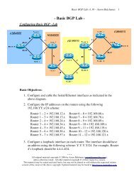
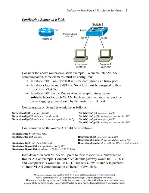
Configuring <strong>Router</strong> on a Stick<br />
MultiLayer <strong>Switching</strong> v1.11 – Aaron Balchunas<br />
Consider the above router-on-a-stick example. To enable inter-VLAN<br />
communication, three elements must be configured:<br />
• Interface fa0/10 on Switch B must be configured as a trunk port.<br />
• Interfaces fa0/14 and fa0/15 on Switch B must be assigned to their<br />
respective VLANs.<br />
• Interface fa0/1 on the <strong>Router</strong> A must be split into separate<br />
subinterfaces for each VLAN. Each subinterface must support the<br />
frame-tagging protocol used by the switch’s trunk port.<br />
Configuration on Switch B would be as follows:<br />
Switch(config)# interface fa0/10<br />
Switch(config-if)# switchport mode trunk<br />
Switch(config-if)# switchport trunk encapsulation dot1q<br />
Configuration on the <strong>Router</strong> A would be as follows:<br />
<strong>Router</strong>(config)# interface fa0/1<br />
<strong>Router</strong>(config-if)# no shut<br />
<strong>Router</strong>(config)# interface fa0/1.101<br />
<strong>Router</strong>(config-subif)# encapsulation dot1q 101<br />
<strong>Router</strong>(config-subif)# ip address 172.16.1.1 255.255.0.0<br />
Switch(config)# interface fa0/14<br />
Switch(config-if)# switchport access vlan 101<br />
Switch(config)# interface fa0/15<br />
Switch(config-if)# switchport access vlan 102<br />
<strong>Router</strong>(config)# interface fa0/1.102<br />
<strong>Router</strong>(config-subif)# encapsulation dot1q 102<br />
<strong>Router</strong>(config-subif)# ip address 10.1.1.1 255.255.0.0<br />
Host devices in each VLAN will point to their respective subinterface on<br />
<strong>Router</strong> A. For example, Computer A’s default gateway would be 172.16.1.1,<br />
and Computer B’s would be 10.1.1.1. This will allow <strong>Router</strong> A to perform<br />
all inter-VLAN communication on behalf of Switch B.<br />
* * *<br />
All original material copyright © 2009 by Aaron Balchunas (aaron@routeralley.com),<br />
unless otherwise noted. All other material copyright © of their respective owners.<br />
This material may be copied and used freely, but may not be altered or sold without the expressed written<br />
consent of the owner of the above copyright. Updated material may be found at http://www.routeralley.com.<br />
2