Multilayer Switching - Router Alley
Multilayer Switching - Router Alley
Multilayer Switching - Router Alley

Create successful ePaper yourself
Turn your PDF publications into a flip-book with our unique Google optimized e-Paper software.
Routing Between VLANs<br />
MultiLayer <strong>Switching</strong> v1.11 – Aaron Balchunas<br />
- <strong>Multilayer</strong> <strong>Switching</strong> -<br />
VLANs separate a Layer-2 switch into multiple broadcast domains. Each<br />
VLAN becomes its own individual broadcast domain (or IP subnet). Only<br />
interfaces belonging to the same VLAN can communicate without an<br />
intervening device. Interfaces assigned to separate VLANS require a router<br />
to communicate.<br />
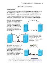
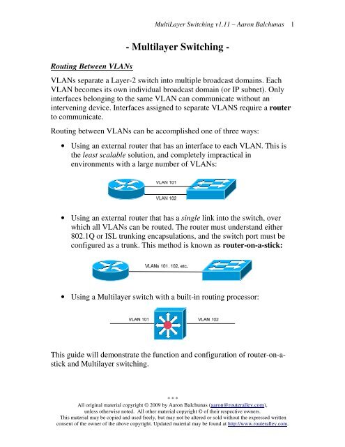
Routing between VLANs can be accomplished one of three ways:<br />
• Using an external router that has an interface to each VLAN. This is<br />
the least scalable solution, and completely impractical in<br />
environments with a large number of VLANs:<br />
• Using an external router that has a single link into the switch, over<br />
which all VLANs can be routed. The router must understand either<br />
802.1Q or ISL trunking encapsulations, and the switch port must be<br />
configured as a trunk. This method is known as router-on-a-stick:<br />
• Using a <strong>Multilayer</strong> switch with a built-in routing processor:<br />
This guide will demonstrate the function and configuration of router-on-astick<br />
and <strong>Multilayer</strong> switching.<br />
* * *<br />
All original material copyright © 2009 by Aaron Balchunas (aaron@routeralley.com),<br />
unless otherwise noted. All other material copyright © of their respective owners.<br />
This material may be copied and used freely, but may not be altered or sold without the expressed written<br />
consent of the owner of the above copyright. Updated material may be found at http://www.routeralley.com.<br />
1
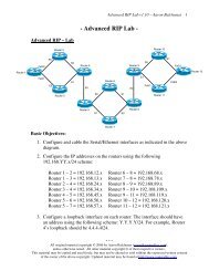
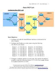
Configuring <strong>Router</strong> on a Stick<br />
MultiLayer <strong>Switching</strong> v1.11 – Aaron Balchunas<br />
Consider the above router-on-a-stick example. To enable inter-VLAN<br />
communication, three elements must be configured:<br />
• Interface fa0/10 on Switch B must be configured as a trunk port.<br />
• Interfaces fa0/14 and fa0/15 on Switch B must be assigned to their<br />
respective VLANs.<br />
• Interface fa0/1 on the <strong>Router</strong> A must be split into separate<br />
subinterfaces for each VLAN. Each subinterface must support the<br />
frame-tagging protocol used by the switch’s trunk port.<br />
Configuration on Switch B would be as follows:<br />
Switch(config)# interface fa0/10<br />
Switch(config-if)# switchport mode trunk<br />
Switch(config-if)# switchport trunk encapsulation dot1q<br />
Configuration on the <strong>Router</strong> A would be as follows:<br />
<strong>Router</strong>(config)# interface fa0/1<br />
<strong>Router</strong>(config-if)# no shut<br />
<strong>Router</strong>(config)# interface fa0/1.101<br />
<strong>Router</strong>(config-subif)# encapsulation dot1q 101<br />
<strong>Router</strong>(config-subif)# ip address 172.16.1.1 255.255.0.0<br />
Switch(config)# interface fa0/14<br />
Switch(config-if)# switchport access vlan 101<br />
Switch(config)# interface fa0/15<br />
Switch(config-if)# switchport access vlan 102<br />
<strong>Router</strong>(config)# interface fa0/1.102<br />
<strong>Router</strong>(config-subif)# encapsulation dot1q 102<br />
<strong>Router</strong>(config-subif)# ip address 10.1.1.1 255.255.0.0<br />
Host devices in each VLAN will point to their respective subinterface on<br />
<strong>Router</strong> A. For example, Computer A’s default gateway would be 172.16.1.1,<br />
and Computer B’s would be 10.1.1.1. This will allow <strong>Router</strong> A to perform<br />
all inter-VLAN communication on behalf of Switch B.<br />
* * *<br />
All original material copyright © 2009 by Aaron Balchunas (aaron@routeralley.com),<br />
unless otherwise noted. All other material copyright © of their respective owners.<br />
This material may be copied and used freely, but may not be altered or sold without the expressed written<br />
consent of the owner of the above copyright. Updated material may be found at http://www.routeralley.com.<br />
2
<strong>Multilayer</strong> Switch Port Types<br />
MultiLayer <strong>Switching</strong> v1.11 – Aaron Balchunas<br />
<strong>Multilayer</strong> switches support both Layer-2 (switching) and Layer-3 (routing)<br />
functions. Three port types can exist on <strong>Multilayer</strong> switches:<br />
• Switchports – Layer-2 ports on which MAC addresses are learned.<br />
• Layer-3 Ports – Essentially routing ports on multi-layer switches.<br />
• Switched Virtual Interfaces (SVI) – A VLAN virtual interface<br />
where an IP address can be assigned to the VLAN itself.<br />
The port type for each interface can be modified. By default, on Catalyst<br />
2950’s and 3550’s, all interfaces are switchports.<br />
To configure a port as a switchport:<br />
Switch(config)# interface fa0/10<br />
Switch(config-if)# switchport<br />
To configure a port as a Layer-3 (routing) port, and assign an IP address:<br />
Switch(config)# interface fa0/11<br />
Switch(config-if)# no switchport<br />
Switch(config-if)# ip address 192.168.1.1 255.255.0.0<br />
Switch(config-if)# no shut<br />
To assign an IP address to an SVI (virtual VLAN interface):<br />
Switch(config)# interface vlan 101<br />
Switch(config-if)# ip address 192.168.1.1 255.255.0.0<br />
Switch(config-if)# no shut<br />
Note that the VLAN itself is treated as an interface, and supports most IOS<br />
interface commands. To view the port type of a particular interface:<br />
Switch# show int fa0/10 switchport<br />
Name: Fa0/10<br />
Switchport: Enabled<br />
<br />
A Layer-3 interface would display the following output:<br />
Switch# show int fa0/10 switchport<br />
Name: Fa0/10<br />
Switchport: Disabled<br />
<br />
* * *<br />
All original material copyright © 2009 by Aaron Balchunas (aaron@routeralley.com),<br />
unless otherwise noted. All other material copyright © of their respective owners.<br />
This material may be copied and used freely, but may not be altered or sold without the expressed written<br />
consent of the owner of the above copyright. Updated material may be found at http://www.routeralley.com.<br />
3
<strong>Multilayer</strong> <strong>Switching</strong> Methods<br />
MultiLayer <strong>Switching</strong> v1.11 – Aaron Balchunas<br />
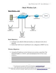
<strong>Multilayer</strong> switches contain both a switching and routing engine. A packet<br />
must first be routed, allowing the switching engine to cache the IP traffic<br />
flow. After this cache is created, subsequent packets destined for that flow<br />
can be switched and not routed, reducing latency.<br />
This concept is often referred to as route once, switch many. Cisco<br />
implemented this type of <strong>Multilayer</strong> switching as NetFlow switching or<br />
route-cache switching.<br />
As is their habit, Cisco replaced NetFlow multilayer switching with a more<br />
advanced method called Cisco Express Forwarding (CEF), to address<br />
some of the disadvantages of route-cache switching:<br />
• CEF is less intensive than Netflow for the multilayer switch CPU.<br />
• CEF does not cache routes, thus there is no danger of having stale<br />
routes in the cache if the routing topology changes.<br />
CEF contains two basic components:<br />
• Layer-3 Engine – Builds the routing table and then routes data<br />
• Layer-3 Forwarding Engine – Switches data based on the FIB.<br />
The Layer-3 Engine builds the routing table using standard methods:<br />
• Static routes.<br />
• Dynamically via a routing protocol (such as RIP or OSPF).<br />
The routing table is then reorganized into a more efficient table called the<br />
Forward Information Base (FIB). The most specific routes are placed at<br />
the top of the FIB. The Layer-3 Forwarding Engine utilizes the FIB to then<br />
switch data in hardware, as opposed to routing it through the Layer-3<br />
Engine’s routing table.<br />
Additionally, CEF maintains an Adjacency Table, containing the hardware<br />
address of the next-hop for each entry in the FIB. Entries in the adjacency<br />
table are populated as new neighboring routers are discovered, using ARP.<br />
This is referred to as gleaning the next-hop hardware address.<br />
Creating an adjacency table eliminates latency from ARP lookups for nexthop<br />
information when data is actually routed/switched.<br />
(Reference: http://www.cisco.com/en/US/docs/ios/12_1/switch/configuration/guide/xcdcef.html)<br />
* * *<br />
All original material copyright © 2009 by Aaron Balchunas (aaron@routeralley.com),<br />
unless otherwise noted. All other material copyright © of their respective owners.<br />
This material may be copied and used freely, but may not be altered or sold without the expressed written<br />
consent of the owner of the above copyright. Updated material may be found at http://www.routeralley.com.<br />
4
CEF Configuration<br />
MultiLayer <strong>Switching</strong> v1.11 – Aaron Balchunas<br />
CEF is enabled by default on all Catalyst multi-layer switches that support<br />
CEF. CEF cannot even be disabled on Catalyst 3550, 4500 and 6500<br />
switches.<br />
To manually enable CEF:<br />
Switch(config)# ip cef<br />
To disable CEF on a specific interface:<br />
Switch(config)# interface fa0/24<br />
Switch(config-if)# no ip route-cache cef<br />
To view the CEF Forward Information Base (FIB) table:<br />
Switch# show ip cef<br />
Prefix Next Hop Interface<br />
172.16.1.0/24 10.5.1.1 Vlan100<br />
172.16.2.0/24 10.5.1.2 Vlan100<br />
172.16.0.0/16 10.5.1.2 Vlan100<br />
0.0.0.0/0 10.1.1.1 Vlan42<br />
Note that the FIB contains the following information:<br />
• The destination prefix (and mask)<br />
• The next-hop address<br />
• The interface the next-hop device exists off of<br />
The most specific routes are placed at the top of the FIB. To view the CEF<br />
Adjacency table:<br />
Switch# show adjacency<br />
Protocol Interface Address<br />
IP Vlan100 10.5.1.1(6)<br />
0 packets, 0 bytes<br />
0001234567891112abcdef120800<br />
ARP 01:42:69<br />
Protocol Interface Address<br />
IP Vlan100 10.5.1.2(6)<br />
0 packets, 0 bytes<br />
000C765412421112abcdef120800<br />
ARP 01:42:69<br />
* * *<br />
All original material copyright © 2009 by Aaron Balchunas (aaron@routeralley.com),<br />
unless otherwise noted. All other material copyright © of their respective owners.<br />
This material may be copied and used freely, but may not be altered or sold without the expressed written<br />
consent of the owner of the above copyright. Updated material may be found at http://www.routeralley.com.<br />
5
<strong>Multilayer</strong> <strong>Switching</strong> vs. <strong>Router</strong> on a Stick<br />
MultiLayer <strong>Switching</strong> v1.11 – Aaron Balchunas<br />
The configuration of router-on-a-stick was demonstrated earlier in this<br />
section. Unfortunately, there are inherent disadvantages to router-on-a-stick:<br />
• There may be insufficient bandwidth for each VLAN, as all routed<br />
traffic will need to share the same router interface.<br />
• There will be an increased load on the router processor, to support the<br />
ISL or DOT1Q encapsulation taking place.<br />
A more efficient (though often more expensive) alternative is to use a<br />
multilayer switch.<br />
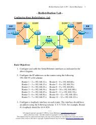
Configuration of inter-VLAN routing on a multilayer switch is simple. First,<br />
create the required VLANs:<br />
Switch(config)# vlan 101<br />
Switch(config-vlan)# name VLAN101<br />
Switch(config)# vlan 102<br />
Switch(config-vlan)# name VLAN102<br />
Then, routing must be globally enabled on the multilayer switch:<br />
Switch(config)# ip routing<br />
Next, each VLAN SVI is assigned an IP address:<br />
Switch(config)# interface vlan 101<br />
Switch(config-if)# ip address 192.168.1.1 255.255.0.0<br />
Switch(config-if)# no shut<br />
Switch(config)# interface vlan 102<br />
Switch(config-if)# ip address 10.1.1.1 255.255.0.0<br />
Switch(config-if)# no shut<br />
These IP addresses will serve as the default gateways for the clients on each<br />
VLAN. By adding an IP address to a VLAN, those networks will be added<br />
to the routing table as directly connected routes, allowing routing to occur.<br />
* * *<br />
All original material copyright © 2009 by Aaron Balchunas (aaron@routeralley.com),<br />
unless otherwise noted. All other material copyright © of their respective owners.<br />
This material may be copied and used freely, but may not be altered or sold without the expressed written<br />
consent of the owner of the above copyright. Updated material may be found at http://www.routeralley.com.<br />
6
Fallback Bridging<br />
MultiLayer <strong>Switching</strong> v1.11 – Aaron Balchunas<br />
The Catalyst 3550 only supports IP when using CEF multilayer switching. If<br />
other protocols (IPX, Appletalk, SNA) need to be routed between VLANs,<br />
fallback bridging can be used.<br />
To configure fallback bridging, a bridge-group must first be created. Then<br />
specific VLANs can be assigned to that bridge-group. A maximum of 31<br />
bridge-groups can be created.<br />
Switch(config)# bridge-group 1 protocol vlan-bridge<br />
Switch(config)# interface vlan 100<br />
Switch(config-if)# bridge-group 1<br />
Switch(config)# interface vlan 101<br />
Switch(config-if)# bridge-group 1<br />
The first command creates the bridge-group. The next command place<br />
VLANs 100 and 101 in bridge-group 1. If protocols other than IP utilize<br />
these VLANs, they will be transparently bridged across the VLANs.<br />
To view information about all configured bridge groups:<br />
Switch# show bridge group<br />
* * *<br />
All original material copyright © 2009 by Aaron Balchunas (aaron@routeralley.com),<br />
unless otherwise noted. All other material copyright © of their respective owners.<br />
This material may be copied and used freely, but may not be altered or sold without the expressed written<br />
consent of the owner of the above copyright. Updated material may be found at http://www.routeralley.com.<br />
7