Hubs vs. Switches vs. Routers - Router Alley
Hubs vs. Switches vs. Routers - Router Alley
Hubs vs. Switches vs. Routers - Router Alley

Create successful ePaper yourself
Turn your PDF publications into a flip-book with our unique Google optimized e-Paper software.
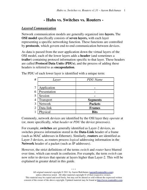
Layered Communication<br />
<strong>Hubs</strong> <strong>vs</strong>. <strong>Switches</strong> <strong>vs</strong>. <strong><strong>Router</strong>s</strong> v1.31 – Aaron Balchunas<br />
- <strong>Hubs</strong> <strong>vs</strong>. <strong>Switches</strong> <strong>vs</strong>. <strong><strong>Router</strong>s</strong> -<br />
Network communication models are generally organized into layers. The<br />
OSI model specifically consists of seven layers, with each layer<br />
representing a specific networking function. These functions are controlled<br />
by protocols, which govern end-to-end communication between devices.<br />
As data is passed from the user application down the virtual layers of the<br />
OSI model, each of the lower layers adds a header (and sometimes a<br />
trailer) containing protocol information specific to that layer. These headers<br />
are called Protocol Data Units (PDUs), and the process of adding these<br />
headers is referred to as encapsulation.<br />
The PDU of each lower layer is identified with a unique term:<br />
# Layer PDU Name<br />
7 Application -<br />
6 Presentation -<br />
5 Session -<br />
4 Transport Segments<br />
3 Network Packets<br />
2 Data-link Frames<br />
1 Physical Bits<br />
Commonly, network devices are identified by the OSI layer they operate at<br />
(or, more specifically, what header or PDU the device processes).<br />
For example, switches are generally identified as Layer-2 devices, as<br />
switches process information stored in the Data-Link header of a frame<br />
(such as MAC addresses in Ethernet). Similarly, routers are identified as<br />
Layer-3 devices, as routers process logical addressing information in the<br />
Network header of a packet (such as IP addresses).<br />
However, the strict definitions of the terms switch and router have blurred<br />
over time, which can result in confusion. For example, the term switch can<br />
now refer to devices that operate at layers higher than Layer-2. This will be<br />
explained in greater detail in this guide.<br />
* * *<br />
All original material copyright © 2011 by Aaron Balchunas (aaron@routeralley.com),<br />
unless otherwise noted. All other material copyright © of their respective owners.<br />
This material may be copied and used freely, but may not be altered or sold without the expressed written<br />
consent of the owner of the above copyright. Updated material may be found at http://www.routeralley.com.<br />
1
Icons for Network Devices<br />
<strong>Hubs</strong> <strong>vs</strong>. <strong>Switches</strong> <strong>vs</strong>. <strong><strong>Router</strong>s</strong> v1.31 – Aaron Balchunas<br />
The following icons will be used to represent network devices for all guides<br />
on routeralley.com:<br />
Hub____ Switch___<br />
Multilayer Switch<br />
<strong>Router</strong><br />
* * *<br />
All original material copyright © 2011 by Aaron Balchunas (aaron@routeralley.com),<br />
unless otherwise noted. All other material copyright © of their respective owners.<br />
This material may be copied and used freely, but may not be altered or sold without the expressed written<br />
consent of the owner of the above copyright. Updated material may be found at http://www.routeralley.com.<br />
2
Layer-1 <strong>Hubs</strong><br />
<strong>Hubs</strong> <strong>vs</strong>. <strong>Switches</strong> <strong>vs</strong>. <strong><strong>Router</strong>s</strong> v1.31 – Aaron Balchunas<br />
<strong>Hubs</strong> are Layer-1 devices that physically connect network devices together<br />
for communication. <strong>Hubs</strong> can also be referred to as repeaters.<br />
<strong>Hubs</strong> provide no intelligent forwarding whatsoever. <strong>Hubs</strong> are incapable of<br />
processing either Layer-2 or Layer-3 information, and thus cannot make<br />
decisions based on hardware or logical addressing.<br />
Thus, hubs will always forward every frame out every port, excluding the<br />
port originating the frame. <strong>Hubs</strong> do not differentiate between frame types,<br />
and thus will always forward unicasts, multicasts, and broadcasts out every<br />
port but the originating port.<br />
Ethernet hubs operate at half-duplex, which allows a device to either<br />
transmit or receive data, but not simultaneously. Ethernet utilizes Carrier<br />
Sense Multiple Access with Collision Detect (CSMA/CD) to control<br />
media access. Host devices monitor the physical link, and will only transmit<br />
a frame if the link is idle.<br />
However, if two devices transmit a frame simultaneously, a collision will<br />
occur. If a collision is detected, the hub will discard the frames and signal<br />
the host devices. Both devices will wait a random amount of time before<br />
resending their respective frames.<br />
Remember, if any two devices connected to a hub send a frame<br />
simultaneously, a collision will occur. Thus, all ports on a hub belong to the<br />
same collision domain. A collision domain is simply defined as any<br />
physical segment where a collision can occur.<br />
Multiple hubs that are uplinked together still all belong to one collision<br />
domain. Increasing the number of host devices in a single collision domain<br />
will increase the number of collisions, which can significantly degrade<br />
performance.<br />
<strong>Hubs</strong> also belong to only one broadcast domain – a hub will forward both<br />
broadcasts and multicasts out every port but the originating port. A broadcast<br />
domain is a logical segmentation of a network, dictating how far a broadcast<br />
(or multicast) frame can propagate.<br />
Only a Layer-3 device, such as a router, can separate broadcast domains.<br />
* * *<br />
All original material copyright © 2011 by Aaron Balchunas (aaron@routeralley.com),<br />
unless otherwise noted. All other material copyright © of their respective owners.<br />
This material may be copied and used freely, but may not be altered or sold without the expressed written<br />
consent of the owner of the above copyright. Updated material may be found at http://www.routeralley.com.<br />
3
Layer-2 Switching<br />
<strong>Hubs</strong> <strong>vs</strong>. <strong>Switches</strong> <strong>vs</strong>. <strong><strong>Router</strong>s</strong> v1.31 – Aaron Balchunas<br />
Layer-2 devices build hardware address tables, which will contain the<br />
following at a minimum:<br />
• Hardware addresses for host devices<br />
• The port each hardware address is associated with<br />
Using this information, Layer-2 devices will make intelligent forwarding<br />
decisions based on frame (Data-Link) headers. A frame can then be<br />
forwarded out only the appropriate destination port, instead of all ports.<br />
Layer-2 forwarding was originally referred to as bridging. Bridging is a<br />
largely deprecated term (mostly for marketing purposes), and Layer-2<br />
forwarding is now commonly referred to as switching.<br />
There are some subtle technological differences between bridging and<br />
switching. <strong>Switches</strong> usually have a higher port-density, and can perform<br />
forwarding decisions at wire speed, due to specialized hardware circuits<br />
called ASICs (Application-Specific Integrated Circuits). Otherwise,<br />
bridges and switches are nearly identical in function.<br />
Ethernet switches build MAC-address tables through a dynamic learning<br />
process. A switch behaves much like a hub when first powered on. The<br />
switch will flood every frame, including unicasts, out every port but the<br />
originating port.<br />
The switch will then build the MAC-address table by examining the source<br />
MAC address of each frame. Consider the following diagram:<br />
Switch<br />
Computer A<br />
Fa0/10 Fa0/11<br />
Computer B<br />
When ComputerA sends a frame to<br />
ComputerB, the switch will add ComputerA’s<br />
MAC address to its table, associating it with<br />
port fa0/10. However, the switch will not<br />
learn ComputerB’s MAC address until<br />
ComputerB sends a frame to ComputerA, or<br />
to another device connected to the switch.<br />
<strong>Switches</strong> always learn from the source<br />
MAC address.<br />
A switch is in a perpetual state of learning. However, as the MAC-address<br />
table becomes populated, the flooding of frames will decrease, allowing the<br />
switch to perform more efficient forwarding decisions.<br />
* * *<br />
All original material copyright © 2011 by Aaron Balchunas (aaron@routeralley.com),<br />
unless otherwise noted. All other material copyright © of their respective owners.<br />
This material may be copied and used freely, but may not be altered or sold without the expressed written<br />
consent of the owner of the above copyright. Updated material may be found at http://www.routeralley.com.<br />
4
Layer-2 Switching (continued)<br />
<strong>Hubs</strong> <strong>vs</strong>. <strong>Switches</strong> <strong>vs</strong>. <strong><strong>Router</strong>s</strong> v1.31 – Aaron Balchunas<br />
While hubs were limited to half-duplex communication, switches can<br />
operate in full duplex. Each individual port on a switch belongs to its own<br />
collision domain. Thus, switches create more collision domains, which<br />
results in fewer collisions.<br />
Like hubs though, switches belong to only one broadcast domain. A Layer-<br />
2 switch will forward both broadcasts and multicasts out every port but the<br />
originating port. Only Layer-3 devices separate broadcast domains.<br />
Because of this, Layer-2 switches are poorly suited for large, scalable<br />
networks. The Layer-2 header provides no mechanism to differentiate one<br />
network from another, only one host from another.<br />
This poses significant difficulties. If only hardware addressing existed, all<br />
devices would technically be on the same network. Modern internetworks<br />
like the Internet could not exist, as it would be impossible to separate my<br />
network from your network.<br />
Imagine if the entire Internet existed purely as a Layer-2 switched<br />
environment. <strong>Switches</strong>, as a rule, will forward a broadcast out every port.<br />
Even with a conservative estimate of a billion devices on the Internet, the<br />
resulting broadcast storms would be devastating. The Internet would simply<br />
collapse.<br />
Both hubs and switches are susceptible to switching loops, which result in<br />
destructive broadcast storms. <strong>Switches</strong> utilize the Spanning Tree Protocol<br />
(STP) to maintain a loop-free environment. STP is covered in great detail in<br />
another guide.<br />
Remember, there are three things that switches do that hubs do not:<br />
• Hardware address learning<br />
• Intelligent forwarding of frames<br />
• Loop avoidance<br />
<strong>Hubs</strong> are almost entirely deprecated – there is no advantage to using a hub<br />
over a switch. At one time, switches were more expensive and introduced<br />
more latency (due to processing overhead) than hubs, but this is no longer<br />
the case.<br />
* * *<br />
All original material copyright © 2011 by Aaron Balchunas (aaron@routeralley.com),<br />
unless otherwise noted. All other material copyright © of their respective owners.<br />
This material may be copied and used freely, but may not be altered or sold without the expressed written<br />
consent of the owner of the above copyright. Updated material may be found at http://www.routeralley.com.<br />
5
Layer-2 Forwarding Methods<br />
<strong>Hubs</strong> <strong>vs</strong>. <strong>Switches</strong> <strong>vs</strong>. <strong><strong>Router</strong>s</strong> v1.31 – Aaron Balchunas<br />
<strong>Switches</strong> support three methods of forwarding frames. Each method copies<br />
all or part of the frame into memory, providing different levels of latency<br />
and reliability. Latency is delay - less latency results in quicker forwarding.<br />
The Store-and-Forward method copies the entire frame into memory, and<br />
performs a Cycle Redundancy Check (CRC) to completely ensure the<br />
integrity of the frame. However, this level of error-checking introduces the<br />
highest latency of any of the switching methods.<br />
The Cut-Through (Real Time) method copies only enough of a frame’s<br />
header to determine its destination address. This is generally the first 6 bytes<br />
following the preamble. This method allows frames to be transferred at wire<br />
speed, and has the least latency of any of the three methods. No error<br />
checking is attempted when using the cut-through method.<br />
The Fragment-Free (Modified Cut-Through) method copies only the first<br />
64 bytes of a frame for error-checking purposes. Most collisions or<br />
corruption occur in the first 64 bytes of a frame. Fragment-Free represents a<br />
compromise between reliability (store-and-forward) and speed (cut-through).<br />
* * *<br />
All original material copyright © 2011 by Aaron Balchunas (aaron@routeralley.com),<br />
unless otherwise noted. All other material copyright © of their respective owners.<br />
This material may be copied and used freely, but may not be altered or sold without the expressed written<br />
consent of the owner of the above copyright. Updated material may be found at http://www.routeralley.com.<br />
6
Layer-3 Routing<br />
<strong>Hubs</strong> <strong>vs</strong>. <strong>Switches</strong> <strong>vs</strong>. <strong><strong>Router</strong>s</strong> v1.31 – Aaron Balchunas<br />
Layer-3 routing is the process of forwarding a packet from one network to<br />
another network, based on the Network-layer header. <strong><strong>Router</strong>s</strong> build routing<br />
tables to perform forwarding decisions, which contain the following:<br />
• The destination network and subnet mask<br />
• The next hop router to get to the destination network<br />
• Routing metrics and Administrative Distance<br />
Note that Layer-3 forwarding is based on the destination network, and not<br />
the destination host. It is possible to have host routes, but this is less<br />
common.<br />
The routing table is concerned with two types of Layer-3 protocols:<br />
• Routed protocols - assigns logical addressing to devices, and routes<br />
packets between networks. Examples include IP and IPX.<br />
• Routing protocols - dynamically builds the information in routing<br />
tables. Examples include RIP, EIGRP, and OSPF.<br />
Each individual interface on a router belongs to its own collision domain.<br />
Thus, like switches, routers create more collision domains, which results in<br />
fewer collisions.<br />
Unlike Layer-2 switches, Layer-3 routers also separate broadcast domains.<br />
As a rule, a router will never forward broadcasts from one network to<br />
another network (unless, of course, you explicitly configure it to). ☺<br />
<strong><strong>Router</strong>s</strong> will not forward multicasts either, unless configured to participate in<br />
a multicast tree. Multicast is covered in great detail in another guide.<br />
Traditionally, a router was required to copy each individual packet to its<br />
buffers, and perform a route-table lookup. Each packet consumed CPU<br />
cycles as it was forwarded by the router, resulting in latency. Thus, routing<br />
was generally considered slower than switching.<br />
It is now possible for routers to cache network-layer flows in hardware,<br />
greatly reducing latency. This has blurred the line between routing and<br />
switching, from both a technological and marketing standpoint. Caching<br />
network flows is covered in greater detail shortly.<br />
* * *<br />
All original material copyright © 2011 by Aaron Balchunas (aaron@routeralley.com),<br />
unless otherwise noted. All other material copyright © of their respective owners.<br />
This material may be copied and used freely, but may not be altered or sold without the expressed written<br />
consent of the owner of the above copyright. Updated material may be found at http://www.routeralley.com.<br />
7
Collision <strong>vs</strong>. Broadcast Domain Example<br />
<strong>Hubs</strong> <strong>vs</strong>. <strong>Switches</strong> <strong>vs</strong>. <strong><strong>Router</strong>s</strong> v1.31 – Aaron Balchunas<br />
Consider the above diagram. Remember that:<br />
• <strong><strong>Router</strong>s</strong> separate broadcast and collision domains.<br />
• <strong>Switches</strong> separate collision domains.<br />
• <strong>Hubs</strong> belong to only one collision domain.<br />
• <strong>Switches</strong> and hubs both only belong to one broadcast domain.<br />
In the above example, there are THREE broadcast domains, and EIGHT<br />
collision domains:<br />
* * *<br />
All original material copyright © 2011 by Aaron Balchunas (aaron@routeralley.com),<br />
unless otherwise noted. All other material copyright © of their respective owners.<br />
This material may be copied and used freely, but may not be altered or sold without the expressed written<br />
consent of the owner of the above copyright. Updated material may be found at http://www.routeralley.com.<br />
8
VLANs – A Layer-2 or Layer-3 Function?<br />
<strong>Hubs</strong> <strong>vs</strong>. <strong>Switches</strong> <strong>vs</strong>. <strong><strong>Router</strong>s</strong> v1.31 – Aaron Balchunas<br />
By default, a switch will forward both broadcasts and multicasts out every<br />
port but the originating port.<br />
However, a switch can be logically segmented into multiple broadcast<br />
domains, using Virtual LANs (or VLANs). VLANs are covered in<br />
extensive detail in another guide.<br />
Each VLAN represents a unique broadcast domain:<br />
• Traffic between devices within the same VLAN is switched<br />
(forwarded at Layer-2).<br />
• Traffic between devices in different VLANs requires a Layer-3<br />
device to communicate.<br />
Broadcasts from one VLAN will not be forwarded to another VLAN. This<br />
separation provided by VLANs is not a Layer-3 function. VLAN tags are<br />
inserted into the Layer-2 header.<br />
Thus, a switch that supports VLANs is not necessarily a Layer-3 switch.<br />
However, a purely Layer-2 switch cannot route between VLANs.<br />
Remember, though VLANs provide separation for Layer-3 broadcast<br />
domains, and are often associated with IP subnets, they are still a Layer-2<br />
function.<br />
* * *<br />
All original material copyright © 2011 by Aaron Balchunas (aaron@routeralley.com),<br />
unless otherwise noted. All other material copyright © of their respective owners.<br />
This material may be copied and used freely, but may not be altered or sold without the expressed written<br />
consent of the owner of the above copyright. Updated material may be found at http://www.routeralley.com.<br />
9
Layer-3 Switching<br />
<strong>Hubs</strong> <strong>vs</strong>. <strong>Switches</strong> <strong>vs</strong>. <strong><strong>Router</strong>s</strong> v1.31 – Aaron Balchunas 10<br />
In addition to performing Layer-2 switching functions, a Layer-3 switch<br />
must also meet the following criteria:<br />
• The switch must be capable of making Layer-3 forwarding decisions<br />
(traditionally referred to as routing).<br />
• The switch must cache network traffic flows, so that Layer-3<br />
forwarding can occur in hardware.<br />
Many older modular switches support Layer-3 route processors – this alone<br />
does not qualify as Layer-3 switching. Layer-2 and Layer-3 processors can<br />
act independently within a single switch chassis, with each packet requiring<br />
a route-table lookup on the route processor.<br />
Layer-3 switches leverage ASICs to perform Layer-3 forwarding in<br />
hardware. For the first packet of a particular traffic flow, the Layer-3 switch<br />
will perform a standard route-table lookup. This flow is then cached in<br />
hardware – which preserves required routing information, such as the<br />
destination network and the MAC address of the corresponding next-hop.<br />
Subsequent packets of that flow will bypass the route-table lookup, and will<br />
be forwarded based on the cached information, reducing latency. This<br />
concept is known as route once, switch many.<br />
Layer-3 switches are predominantly used to route between VLANs:<br />
Traffic between devices within the same VLAN, such as ComputerA and<br />
ComputerB, is switched at Layer-2 as normal. The first packet between<br />
devices in different VLANs, such as ComputerA and ComputerD, is routed.<br />
The switch will then cache that IP traffic flow, and subsequent packets in<br />
that flow will be switched in hardware.<br />
* * *<br />
All original material copyright © 2011 by Aaron Balchunas (aaron@routeralley.com),<br />
unless otherwise noted. All other material copyright © of their respective owners.<br />
This material may be copied and used freely, but may not be altered or sold without the expressed written<br />
consent of the owner of the above copyright. Updated material may be found at http://www.routeralley.com.
<strong>Hubs</strong> <strong>vs</strong>. <strong>Switches</strong> <strong>vs</strong>. <strong><strong>Router</strong>s</strong> v1.31 – Aaron Balchunas 11<br />
Layer-3 Switching <strong>vs</strong>. Routing – End the Confusion!<br />
The evolution of network technologies has led to considerable confusion<br />
over the terms switch and router. Remember the following:<br />
• The traditional definition of a switch is a device that performs Layer-2<br />
forwarding decisions.<br />
• The traditional definition of a router is a device that performs Layer-3<br />
forwarding decisions.<br />
Remember also that, switching functions were typically performed in<br />
hardware, and routing functions were typically performed in software. This<br />
resulted in a widespread perception that switching was fast, and routing was<br />
slow (and expensive).<br />
Once Layer-3 forwarding became available in hardware, marketing gurus<br />
muddied the waters by distancing themselves from the term router. Though<br />
Layer-3 forwarding in hardware is still routing in every technical sense, such<br />
devices were rebranded as Layer-3 switches.<br />
Ignore the marketing noise. A Layer-3 switch is still a router.<br />
Compounding matters further, most devices still currently referred to as<br />
routers can perform Layer-3 forwarding in hardware as well. Thus, both<br />
Layer-3 switches and Layer-3 routers perform nearly identical functions at<br />
the same performance.<br />
There are some differences in implementation between Layer-3 switches and<br />
routers, including (but not limited to):<br />
• Layer-3 switches are optimized for Ethernet, and are predominantly<br />
used for inter-VLAN routing. Layer-3 switches can also provide<br />
Layer-2 functionality for intra-VLAN traffic.<br />
• <strong>Switches</strong> generally have higher port densities than routers, and are<br />
considerably cheaper per port than routers (for Ethernet, at least).<br />
• <strong><strong>Router</strong>s</strong> support a large number of WAN technologies, while Layer-3<br />
switches generally do not.<br />
• <strong><strong>Router</strong>s</strong> generally support more advanced feature sets.<br />
Layer-3 switches are often deployed as the backbone of LAN or campus<br />
networks. <strong><strong>Router</strong>s</strong> are predominantly used on network perimeters,<br />
connecting to WAN environments.<br />
(Fantastic Reference: http://blog.ioshints.info/2011/02/how-did-we-ever-get-into-this-switching.html)<br />
* * *<br />
All original material copyright © 2011 by Aaron Balchunas (aaron@routeralley.com),<br />
unless otherwise noted. All other material copyright © of their respective owners.<br />
This material may be copied and used freely, but may not be altered or sold without the expressed written<br />
consent of the owner of the above copyright. Updated material may be found at http://www.routeralley.com.
Multilayer Switching<br />
<strong>Hubs</strong> <strong>vs</strong>. <strong>Switches</strong> <strong>vs</strong>. <strong><strong>Router</strong>s</strong> v1.31 – Aaron Balchunas 12<br />
Multilayer switching is a generic term, referring to any switch that<br />
forwards traffic at layers higher than Layer-2. Thus, a Layer-3 switch is<br />
considered a multilayer switch, as it forwards frames at Layer-2 and packets<br />
at Layer-3.<br />
A Layer-4 switch provides the same functionality as a Layer-3 switch, but<br />
will additionally examine and cache Transport-layer application flow<br />
information, such as the TCP or UDP port.<br />
By caching application flows, QoS (Quality of Service) functions can be<br />
applied to preferred applications.<br />
Consider the following example:<br />
Network and application traffic flows from ComputerA to the Webserver<br />
and Fileserver will be cached. If the traffic to the Webserver is preferred,<br />
then a higher QoS priority can be assigned to that application flow.<br />
Some advanced multilayer switches can provide load balancing, content<br />
management, and other application-level services. These switches are<br />
sometimes referred to as Layer-7 switches.<br />
* * *<br />
All original material copyright © 2011 by Aaron Balchunas (aaron@routeralley.com),<br />
unless otherwise noted. All other material copyright © of their respective owners.<br />
This material may be copied and used freely, but may not be altered or sold without the expressed written<br />
consent of the owner of the above copyright. Updated material may be found at http://www.routeralley.com.