Basler L301kc - BFi OPTiLAS
Basler L301kc - BFi OPTiLAS
Basler L301kc - BFi OPTiLAS
- TAGS
- basler
- optilas
- bfioptilas.com

You also want an ePaper? Increase the reach of your titles
YUMPU automatically turns print PDFs into web optimized ePapers that Google loves.
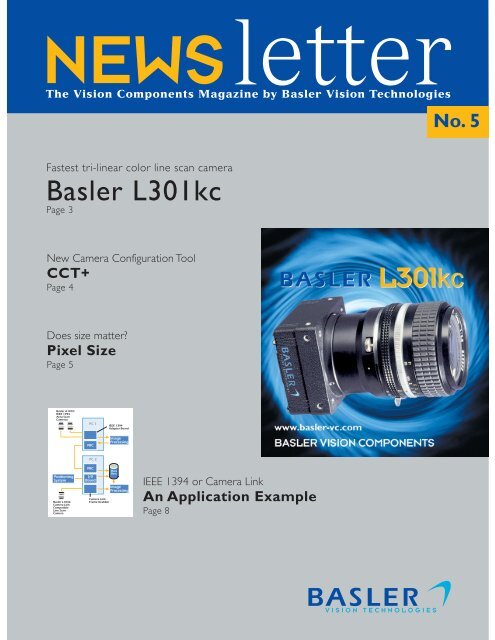
NEWSletter<br />
The Vision Components Magazine by <strong>Basler</strong> Vision Technologies<br />
Fastest tri-linear color line scan camera<br />
<strong>Basler</strong> <strong>L301kc</strong><br />
Page 3<br />
New Camera Configuration Tool<br />
CCT+<br />
Page 4<br />
Does size matter?<br />
Pixel Size<br />
Page 5<br />
<strong>Basler</strong> A101fc<br />
IEEE 1394<br />
Area Scan<br />
Cameras<br />
Positioning<br />
System<br />
<strong>Basler</strong> L104b<br />
Camera Link<br />
Compatible<br />
Line Scan<br />
Camera<br />
PC 1<br />
NIC<br />
PC 2<br />
NIC<br />
I/0<br />
Board<br />
Camera Link<br />
Frame Grabber<br />
IEEE 1394<br />
Adapter Board<br />
Image<br />
Processing<br />
Data<br />
Base<br />
Image<br />
Processing<br />
IEEE 1394 or Camera Link<br />
An Application Example<br />
Page 8<br />
No. 5
Dr. Ralf S. Pulz<br />
Business Segment Manager<br />
Vision Components<br />
2<br />
Comment<br />
Welcome to the second half of 2002 and the newest<br />
issue of our VC Newsletter – No. 5! This newsletter<br />
includes information on the following topics:<br />
The introduction of the <strong>Basler</strong> <strong>L301kc</strong>.<br />
This camera has been designed to provide the<br />
ultimate in color line scan performance at a very<br />
attractive price. Please review page 3 for more<br />
information.<br />
Re-launch of the Camera Configuration Tool.<br />
The revised configuration tool is called CCT+.<br />
Following a thorough requirements analysis, we<br />
decided to completely redesign the CCT and to<br />
implement many exciting new handling features.<br />
Details about the new CCT+ can be found on<br />
page 4.<br />
IEEE 1394 vs. Camera Link interface technology.<br />
There are two new interface technologies for<br />
industrial digital cameras on the market, IEEE 1394<br />
(FireWire ® ) and Camera Link. Those of you who<br />
spent a long time investigating which interface<br />
technology might best suit your applications, may<br />
have found this to be a somewhat confusing topic.<br />
The article on pages 8 through 10 will hopefully<br />
clear up some of the confusion.<br />
As announced in newsletter No. 4, we will begin<br />
presenting some of our partners in each issue. This<br />
time, you will find articles from Matrox Imaging,<br />
Neuro Check, and Jos. Schneider Optische Werke<br />
GmbH on pages 6 and 7.<br />
In earlier issues, we covered news from the European<br />
and US regions. In this issue, a general survey about<br />
Asia is included. New distributors, sales support,<br />
and application support will enhance our presence<br />
in the Asia Pacific region. More on page 11.<br />
Last but not least, we have introduced a new section<br />
called Technical Corner. Technical Corner is dedicated<br />
to discussions on frequently asked questions from<br />
our customers and partners. If you have any<br />
suggestions, topics, etc., please let us know. This<br />
issue’s topic will be pixel size.<br />
While looking back on a successful first half of year<br />
2002, the entire VC team wishes you much fun in<br />
reading this issue of our newsletter and a profitable<br />
second half of the year.<br />
Sincerely yours,<br />
Dr. Ralf S. Pulz
<strong>Basler</strong> Introduces the <strong>L301kc</strong><br />
<strong>Basler</strong> Vision Components (<strong>Basler</strong>-VC) has announced<br />
the introduction of the <strong>L301kc</strong>, a tri-linear, color<br />
line scan camera. The <strong>L301kc</strong> features a three-line<br />
sensor with 2098 pixels per line. With a maximum<br />
line rate of 9.2 kHz, the <strong>L301kc</strong> ranks as one of the<br />
fastest tri-linear cameras.<br />
The <strong>L301kc</strong> has been designed to provide the ultimate<br />
in color line scan performance at a very attractive<br />
price. Because of its lower level of complexity, the<br />
<strong>L301kc</strong> is much more affordable than the typical<br />
three-sensor color line scan camera. And unlike<br />
three-sensor cameras, the <strong>L301kc</strong> does not require<br />
an expensive matched lens in order to obtain the<br />
best possible image quality. The camera's simple<br />
design also means that it is lightweight, a factor that<br />
can be important in some design applications.<br />
The <strong>L301kc</strong> uses<br />
a three-line<br />
sensor with one<br />
line used to<br />
capture red color<br />
information, one<br />
line used to<br />
capture green<br />
color information,<br />
and one line used to capture blue color information.<br />
Because there is a separation between the lines in<br />
the camera, each line will capture a given area on<br />
the object passing the camera at a different time.<br />
This means that to get full color information for a<br />
given area on the object, the data from three different<br />
line captures must be combined. This process is<br />
commonly called "spatial correction". With earlier<br />
versions of color line scan cameras, the process of<br />
storing and combining the data from different line<br />
captures was performed on the frame grabber. The<br />
<strong>L301kc</strong>, however, includes an integrated spatial<br />
correction feature that stores and combines line<br />
captures right in the camera. And the <strong>L301kc</strong> includes<br />
a set of adjustable parameters that allows the user<br />
to control exactly how the spatial correction task<br />
will be performed. When the <strong>L301kc</strong> is combined<br />
with a position encoder, accurate color reproduction<br />
is easy to achieve.<br />
The "k" designation indicates that the camera is fully<br />
compliant with the new Camera Link standard.<br />
Camera Link is an interface standard that was<br />
developed by a group of camera and frame grabber<br />
manufacturers. Since the <strong>L301kc</strong> is fully Camera Link<br />
compatible, it can be easily integrated with a Camera<br />
Link compatible frame grabber thus lowering system<br />
design time and system cost. A <strong>Basler</strong> Interface<br />
Converter for k type cameras (k-BIC) is also available.<br />
The k-BIC can be used to convert the output of the<br />
camera to standard RS-644 LVDS.<br />
The <strong>L301kc</strong> incorporates the features most popular<br />
with <strong>Basler</strong> customers including: asynchronous image<br />
triggering, electronic exposure control, super compact<br />
size, a precision housing, and built-in test capabilities<br />
for trouble shooting. The camera also includes<br />
Camera Link's new high-speed RS-644 serial<br />
communication capability that can be used for online<br />
parameter setting. A Windows® based Camera<br />
Configuration Tool will be available for the <strong>L301kc</strong><br />
which allows the user to change camera settings<br />
with ease. The <strong>L301kc</strong> has been externally certified<br />
for CE and FCC compliance. Full camera<br />
documentation is available.<br />
Series production of the <strong>L301kc</strong> began in July 2002.<br />
Author: Anthony Pieri, Technical and Marketing<br />
Communications Specialist<br />
Response Number 01<br />
<strong>Basler</strong> <strong>L301kc</strong> _ fastest<br />
tri-linear color line scan<br />
camera with Camera<br />
Link interface<br />
Scan direction<br />
3
Fig. 1: The CCT+ user interface<br />
4<br />
Re-launch of the Camera Configuration Tool<br />
Executive Summary<br />
Innovative new CCT+ for use with our newer<br />
cameras<br />
Available for the A102k, A202k, <strong>L301kc</strong>, and A501k;<br />
more to come<br />
Camera auto-identification<br />
Supports all camera link frame grabbers<br />
Immediate response to setting changes<br />
Resizable window<br />
Categories to enhance usability<br />
Communications trace for experienced users<br />
Interdependencies between features are<br />
explicitly shown<br />
As you may know, all <strong>Basler</strong> cameras can be fully<br />
configured via a serial interface. You are also probably<br />
aware that users can easily setup their cameras with<br />
<strong>Basler</strong>’s popular Camera Configuration Tool (CCT).<br />
Since the first release of this tool back in 1997,<br />
<strong>Basler</strong> cameras have become more and more featurerich.<br />
As a result, the need arose for a complete CCT<br />
redesign. The new configuration tool is called the<br />
CCT+ and it is available from our website. 1 The<br />
CCT+ currently works with the <strong>Basler</strong> A102k, A202k,<br />
<strong>L301kc</strong>, and A501k Camera Link cameras.<br />
Using the CCT+<br />
The CCT+ supports all frame grabbers compliant<br />
with the Camera Link standard. 2 In addition, cameras<br />
can be accessed using a k-BIC and one of the PC’s<br />
standard COM ports. Just start the CCT+ and select<br />
the appropriate port from a drop down list (see fig. 1).<br />
To speed things up, you can place a link on the<br />
desktop and supply the port name via command<br />
line.<br />
The CCT+ will automatically identify the camera<br />
and show a list of all camera parameters with their<br />
current settings (see fig. 1). The list is grouped by<br />
categories to simplify navigation. The window is<br />
fully sizable so you can enlarge it for overview and<br />
shrink it if you want to access only a few properties.<br />
The window will remember its last settings.<br />
There are three types of settings in the list of<br />
parameters: enumerable settings, such as Binning,<br />
which are exposed via a drop-down box, read-only<br />
settings which are printed in gray, and scalar settings,<br />
such as Frame Rate, for which a slider is blended in<br />
at the bottom of the window. For some parameters,<br />
for example Exposure Time, the slider is logarithmic<br />
to give constant relative sensitivity over the whole<br />
range of values. To change a setting incrementally,<br />
either use the cursor keys or type in the setting<br />
directly.<br />
In contrast to the old CCT, the new CCT+<br />
immediately sends any parameter changes to the<br />
camera. This means that dragging the Exposure Time<br />
slider while showing a live image will change the<br />
appearance of the image instantly. This is a great<br />
feature often missed with the older CCT, but it<br />
comes with a small drawback: to avoid inconsistent<br />
parameter sets, the bounds of each parameter must<br />
be restricted. For example, the sum of the area of<br />
interest (AOI) Starting Column plus the AOI Width<br />
must not be greater than the number of horizontal<br />
pixels in the sensor array. As a result, the maximum<br />
setting of the AOI Width depends on the AOI Starting<br />
Column and vice versa. To expose these dependencies<br />
to the user, the CCT+ shows a yellow mark on any<br />
other feature that depends on the currently selected<br />
parameter. In addition, a textual explanation of the<br />
restrictions is displayed in the help window. This<br />
feature will help camera users to understand the<br />
underlying concepts of the camera.<br />
Extended features<br />
The set of parameters that a camera is currently<br />
using (called the work set) can be stored into and<br />
loaded from a file. This feature is useful when cloning<br />
camera settings. Also, the work set can be stored in<br />
one of 15 available user sets and users can define<br />
which user set will be loaded when the camera is<br />
powered up.<br />
To speed up and simplify support, a camera register<br />
dump and any error message the CCT+ might show<br />
can be stored in a file and sent to <strong>Basler</strong> by email.<br />
Expert users who want to program the camera<br />
themselves should look over the Communication<br />
Trace window. In this window, the commands sent<br />
to the camera are listed together with the contents<br />
of the binary protocol used by the tool.<br />
Because the CCT+ only blocks the communication<br />
port during transactions, 3 it can be used in parallel<br />
with other programs accessing the camera, for<br />
example, frame grabber viewer programs. You can
configure the CCT+ to refresh the display repeatedly<br />
to see if other programs are changing camera settings<br />
in the background. Of course, you can also run as<br />
many instances of the CCT+ in parallel as you like<br />
and you can mix the new CCT+ with the classic<br />
CCT.<br />
What to do next<br />
Download the new CCT+ from our website and<br />
give it a try. It is written in Java and comes with an<br />
optional Java Virtual Machine so it will run on any<br />
Win32 machine without problems.<br />
There is a demo mode for each camera available,<br />
so if you want to have a look at how certain camera<br />
features are set before you actually get a camera<br />
for evaluation, the CCT+ is a great place to start.<br />
Technical Corner<br />
Pixel Size – Does It Matter?<br />
Today's marketplace offers a wide variety of sensors<br />
with many different sizes, resolutions, speeds, and<br />
sensitivities. In this article, we outline some of the<br />
effects of pixel size.<br />
Effects on sensor size<br />
A higher pixel size will, of course, result in a larger<br />
sensor. With larger sensors, lens effects such as<br />
shading and distortion may be added to the image.<br />
Effects on the fill factor<br />
For area scan sensors with CMOS and interline<br />
transfer technology, either some ”blind” electronic<br />
devices or some vertical shift registers must be<br />
placed next to the light sensitive areas on the sensor.<br />
The fill factor (ratio of sensitive area to total area)<br />
decreases as the pixels become smaller. Due to this,<br />
you may find micro lenses on sensors with small<br />
pixels. Micro lenses increase the effective fill factor<br />
through optical means.<br />
Effects on MTF<br />
MTF is determined by a combination of sensor and<br />
optics. When using a <strong>Basler</strong> camera, a poor quality<br />
lens can be a major limitation. This is especially true<br />
in the region below a 7 µm pixel size where a good<br />
1 Download the CCT+ from the product range<br />
section (e.g., A100 Series) of our website at<br />
www.basler-vc.com.<br />
2 The frame grabber driver needs to supply a<br />
CLSER***.DLL as described in appendix B of the<br />
Specifications of the Camera Link Interface<br />
Standard for Digital Cameras and Frame Grabbers<br />
(October 2000).<br />
3 This is compliant with the Camera Link Serial<br />
Software Enhancements that will be included in<br />
the upcoming new version of the Camera Link<br />
standard.<br />
Author: Dr. Friedrich Dierks, Software<br />
Development Manager VC-D<br />
Response Number 02<br />
quality lens is needed to resolve the image data to<br />
the pixels. It's clear that to achieve the best<br />
performance with any <strong>Basler</strong> camera, you should<br />
use high quality lenses.<br />
Effects on sensitivity and S/N ratio<br />
Opinions on this subject differ, but experienced<br />
engineers say, "Yes, pixel size does matter! " With<br />
smaller pixels, the lens will focus slightly less light<br />
on the pixels. With less sensitivity, the S/N ratio<br />
trends toward worse behavior, but this effect is<br />
minimal. For example, the difference in S/N ratio<br />
between 10 µm and 14 µm pixels will only be about<br />
20%.<br />
To sum it up<br />
In many respects, pixel size does matter. Bigger pixels<br />
have their advantages but they can also cause<br />
problems. In the end, we come to the conclusion<br />
that the quality of the entire camera must be<br />
considered - that's why <strong>Basler</strong> is here.<br />
Author: Ingo Lewerendt, Product Manager<br />
Vision Components<br />
The CCT+ development team<br />
(from left to right): Margret<br />
Albrecht, Alexander Happe<br />
5
6<br />
Partner Page<br />
No More Bottlenecks with PCI-X<br />
PCI-X is a high-performance enhancement to the<br />
conventional PCI bus specification. This technology,<br />
with its increased performance, addresses the<br />
demanding I/O requirements for high-bandwidth<br />
applications like Gigabit Ethernet and high-speed<br />
CameraLink cameras. Version 1.0 of PCI-X specifies<br />
a 64-bit connection at speeds of 66, 100 or 133 MHz,<br />
resulting in a peak bandwidth of 528, 800 or 1064<br />
Megabytes per second, respectively.<br />
Equally important, PCI-X provides backward<br />
compatibility by allowing devices to operate at<br />
conventional PCI frequencies and modes. PCI-X<br />
peripheral cards can operate in a conventional PCI<br />
slot, although only at PCI rates and may require a<br />
3.3 V conventional PCI slot. Similarly, a PCI peripheral<br />
card with a 3.3 V or universal card edge connector<br />
can operate in a PCI-X slot, however the bus clock<br />
will remain at a frequency acceptable to the PCI<br />
card.<br />
However, as with many technologies, there is a tradeoff.<br />
With PCI-X, speed is sacrificed as the number<br />
NeuroCheck Implements<br />
<strong>Basler</strong> IEEE 1394 Cameras<br />
NeuroCheck GmbH, a medium-sized German<br />
company, develops innovative systems for optical<br />
quality control in production processes. Implemented<br />
in more than 2,500 applications, NeuroCheck’s<br />
software package has proven high performance in<br />
automating visual inspection processes worldwide.<br />
The company's application department develops<br />
turnkey system solutions for optical inspection of<br />
all kinds of products.<br />
Based on years of positive experience with <strong>Basler</strong><br />
cameras, NeuroCheck decided early this year to<br />
of slots per bus segment increases. A 66 MHz<br />
operation allows a maximum of four slots per<br />
segment (compared with a maximum of two slots<br />
for 66 MHz conventional PCI). A 100 MHz operation<br />
allows a maximum two slots per segment, while a<br />
133 MHz operation allows a maximum of one slot<br />
per segment.<br />
Server and workstation class systems and<br />
motherboards are starting to appear with PCI-X<br />
equipped core logic chipsets such as the<br />
ServerWorks Grand Champion series, Intel®<br />
E7500 and the soon-to-arrive AMD-8000 series.<br />
The ePCI-X specification from the PCI Industrial<br />
Computer Manufacturers Group (PICMG) will pave<br />
the way for Industrial PCs with PCI-X slots.<br />
And stay tuned as Matrox Imaging will soon be<br />
announcing an exciting new generation of frame<br />
grabbers and vision processors that take advantage<br />
of PCI-X technology!<br />
Author: Pierantonio Boriero, Product Line Manager<br />
for Matrox Imaging<br />
support the new <strong>Basler</strong> IEEE 1394 cameras in their<br />
version NC5.1 software.<br />
Under Windows 2000 and Windows XP, version<br />
NC5.1 supports all 1394 cameras identified by the<br />
<strong>Basler</strong> BCAM 1394 driver. In theory, an unlimited<br />
number of different color and monochrome cameras<br />
can be operated simultaneously. In the NeuroCheck<br />
Device Manager, the identified cameras are listed in<br />
a tree view. For each device, the user can easily set<br />
the corresponding parameters in the Properties<br />
dialog. In addition to the standard camera settings
defined in the DCAM standard, <strong>Basler</strong> specific<br />
functions such as triggering and test images are easy<br />
to configure. All settings can be included in an export<br />
file and stored in an archive for documentation<br />
purposes.<br />
Since the new 1394 technology eliminates the need<br />
for fine-tuning the camera/framegrabber combination,<br />
integration in NeuroCheck is very simple.<br />
NeuroCheck communicates directly with the camera,<br />
Schneider Kreuznach has introduced two new lenses<br />
to its well-established Macro System family:<br />
Componon-S 5.6/100 and Macro Symmar 5.6/80.<br />
Users benefit from the increased focal length of 28<br />
to 100 mm. And with the Macro Symmar 5.6/80, a<br />
lens is now available that is optimized for a 1:1<br />
magnification ratio.<br />
The lenses of the Macro System are renowned for<br />
their outstanding imaging performance. Due to their<br />
large image circle diameter, they can be combined<br />
with even comparatively large CCD matrix and line<br />
scan sensors of up to 42 mm. Larger sensor sizes<br />
can be supported using the lenses of the Unifoc<br />
58/76 system.<br />
The Macro System is universally applicable. Its<br />
mechanical stability makes it an ideal choice for<br />
industrial applications. Using extension tubes in<br />
different sizes from 6 to 75 mm, these lenses can<br />
it identifies the camera type, and it reads out the<br />
corresponding resolution and setting options. If a<br />
camera is removed during runtime, the user receives<br />
a message and the current checking cycle is stopped<br />
immediately. This functionality represents an intelligent<br />
way of using the operating system's plug & play<br />
mechanism in favor of increased process reliability.<br />
Compared to traditional solutions, NeuroCheck<br />
expects 1394 technology to considerably reduce<br />
the demand for technical support.<br />
Author: Till Pleyer, Marketing NeuroCheck<br />
Schneider Introduces New Macro<br />
Lenses for Image Processing<br />
easily be adapted to the user's specific imaging task.<br />
For focusing, the Unifoc 12 or 6 helical mounts are<br />
used. The large number of camera adapters available,<br />
such as C-Mount, Nikon-Bayonet, and many others,<br />
ensure compatibility with almost any camera type.<br />
The uniform mechanical interface consists of three<br />
grub screws engaging into a groove. This ensures a<br />
solid and permanent connection while offering<br />
multiple combination options of the individual<br />
components. It is even possible to mount the lens<br />
in the reverse position for enlarged imaging.<br />
For further information about the Macro Lenses,<br />
please visit the Schneider web site at<br />
www.schneiderkreuznach.com/industrie<br />
optik_e/makro/makro.htm.<br />
Author: Joerg Blaetz, Vertrieb/Sales<br />
Industrial Optics, Jos. Schneider<br />
Optische Werke GmbH<br />
Adjusting the camera properties in<br />
the NeuroCheck Device Manager<br />
7
8<br />
IEEE 1394 or Camera Link –<br />
Which One Do I Want?<br />
If you've been to a machine vision trade show lately<br />
or if you've looked through any industry related<br />
publication, you know that two new interfaces for<br />
industrial digital cameras were recently introduced.<br />
The new interfaces, Camera Link TM and IEEE 1394<br />
(also known as FireWire ® ) appeared amid much<br />
fanfare and with long lists of supposed advantages<br />
to camera users. But even if you have extensive<br />
experience with digital cameras, the competing claims<br />
and highly technical explanations for each interface<br />
may easily have left you confused about whether<br />
either interface is worth considering in your current<br />
or your future applications.<br />
In this article, we will clear up some of the confusion<br />
by looking at a real world decision-making process<br />
that revolved around the Camera Link and the IEEE<br />
1394 interfaces. Stan Shmia, an applications engineer<br />
for <strong>Basler</strong> Vision Technologies, recently worked with<br />
International Cybernetics and helped them work<br />
through their questions about the two interfaces<br />
and to decide what was appropriate for their<br />
application. Stan's experience with Cybernetics<br />
provides some insights that you might find useful.<br />
Before we go further, you may want to look over<br />
Table 1. It outlines some of the basic characteristics<br />
of the IEEE 1394 and Camera Link interfaces. If you<br />
would like to become even more familiar with the<br />
technical details of the Camera Link or IEEE 1394<br />
interfaces, a key word web search will yield a wealth<br />
of information.<br />
The Cybernetics application<br />
International Cybernetics<br />
develops and manufactures<br />
a variety of equipment<br />
used to examine and<br />
profile highways. Currently,<br />
they are working on a new<br />
piece of equipment that<br />
will employ two truck<br />
mounted camera systems<br />
to examine the condition<br />
of highway striping and<br />
overhead signs (see Fig. 1).<br />
As the truck moves along<br />
a highway, camera system<br />
one uses a high speed line<br />
scan camera to capture<br />
images of the highway striping. Camera system two<br />
uses two medium resolution area scan cameras to<br />
capture images of overhead signs. Proprietary<br />
software is used to evaluate the condition of the<br />
striping and the signs and a positioning system is<br />
used to track the location of the truck on the<br />
highway. Condition and location information are<br />
logged in a database (see Fig. 2). Potential customers<br />
for this equipment include state and local highway<br />
departments who will use the information from the<br />
database to schedule highway maintenance.<br />
For camera system one, an extremely high speed<br />
line scan camera is required. Stan noted that trying<br />
to meet this requirement reveals some of the<br />
limitations of the IEEE 1394 interface and highlights<br />
some of Camera Link's strengths. Currently, the<br />
specifications that govern IEEE 1394 cameras do not<br />
define a line scan camera, so no IEEE 1394 line scan<br />
cameras are available. Also, the IEEE 1394 bus has<br />
a relatively low data rate; it can handle approximately<br />
32 MBytes of image data per second. On the other<br />
hand, Camera Link line scan cameras are readily<br />
available. And with a potential image data rate of up<br />
to approximately 650 MBytes per second, Camera<br />
Link can easily handle the fastest line scan cameras<br />
currently available.<br />
Another interesting consideration is that the standard<br />
electrical interface on Camera Link cameras and<br />
frame grabbers would allow the Cybernetics<br />
engineers to test cameras from several different<br />
manufacturers with a minimum of effort. In the past,<br />
each manufacturer used different connectors, different<br />
cables, and different pin layouts on their products.<br />
This resulted in major headaches for engineers who<br />
wanted to test products from different manufacturers<br />
head to head. The standard connectors and cabling<br />
associated with Camera Link make it much easier<br />
to try different cameras during a development effort.<br />
Keep in mind, however, that you will still need to<br />
obtain a different frame grabber configuration file<br />
for each different camera that you test.<br />
For camera system one, Stan pointed to the Camera<br />
Link cables as a major advantage over the cables used<br />
with older products. Camera Link cables are thinner,<br />
are much more flexible, and are more robust. In the<br />
Cybernetics application where harsh conditions,<br />
vibration, and cable routings with tight curves are all<br />
present, the Camera Link cables are an obvious plus.
Stan's recommendation for camera system one was<br />
a <strong>Basler</strong> L104b 2k monochrome line scan camera.<br />
The L104b is Camera Link compatible and has a<br />
29.2 kHz line rate. At this line rate, the camera can<br />
capture high-resolution images of the highway striping<br />
even when the Cybernetics vehicle is traveling at<br />
highway speeds.<br />
Camera system number two posed a different set<br />
of challenges. The Cybernetics engineers specified<br />
that they needed two medium-resolution area scan<br />
cameras and that the cameras must connect to a<br />
single computer. Since the overhead signs these<br />
cameras will be imaging remain in view for a relatively<br />
long period of time, high frame rates are not required.<br />
Also, since lighting conditions can change dramatically<br />
from moment to moment, the cameras must have<br />
very fast re-parameterization capability. Stan<br />
concluded that cameras using the IEEE 1394 interface<br />
were well suited for this situation. Using an<br />
inexpensive interface board, two cameras can easily<br />
be connected to a single computer. In fact, the ability<br />
to connect multiple cameras to a single bus at a<br />
very low cost is an outstanding advantage of the<br />
IEEE 1394 interface. Stan also pointed out that the<br />
bi-directional nature of the IEEE 1394 bus allows<br />
attached cameras to be re-parameterized before<br />
each image acquisition with little or no effect on the<br />
frame rate. Stan also noted that as with Camera<br />
Link, the cables used with the IEEE 1394 interface<br />
are very flexible and robust. The IEEE 1394 cables<br />
have an additional advantage in that since they are<br />
widely used in many video applications, they are<br />
readily available and tend to be less expensive than<br />
the cables used with Camera Link.<br />
For system number two, Stan recommended using<br />
two <strong>Basler</strong> A101fc IEEE 1394 color area scan cameras.<br />
A101fc cameras have a resolution of 1300 x1030<br />
pixels and a maximum 11.75 fps frame rate. At this<br />
speed and resolution, they can provide high quality<br />
images to the system’s overhead sign condition<br />
analysis software. When these cameras operate at<br />
full resolution and frame rate, they generate<br />
approximately 15 MBytes of image data per second<br />
per camera or a total of 30 MBytes for the two<br />
cameras. This is within the maximum 32 MByte<br />
capacity of the IEEE 1394 bus and means that the<br />
two cameras can be attached to a single IEEE 1394<br />
adapter board while operating at full resolution and<br />
frame rate. Most adapter boards have<br />
multiple IEEE 1394 ports thus allowing<br />
the two A101fc cameras to be<br />
connected directly to a single board.<br />
Some adapter boards also have an<br />
internal connection to the power supply<br />
in the host PC. This connection allows<br />
the board to supply sufficient power<br />
to the two A101fc cameras via the IEEE<br />
1394 cables. You should note that many<br />
adapter boards draw their power from<br />
the PCI bus and do not have a direct<br />
connection to the host computer’s<br />
power supply. In this case, the adapter<br />
boards cannot supply sufficient power<br />
to most cameras and an external IEEE<br />
1394 powered hub must be used.<br />
So in summation, Stan's recommendations for the<br />
Cybernetics development project incorporate both<br />
of the new interfaces and match the strengths of<br />
each interface to the needs of the system. As a result,<br />
Cybernetics will achieve superior performance at a<br />
lower cost.<br />
What about legacy systems?<br />
As the discussion about the new Cybernetics system<br />
progressed, the issue of legacy systems arose.<br />
Cybernetics produced systems in the past that used<br />
digital cameras with RS-644 format video output<br />
and they must be able to maintain those legacy<br />
systems. Their first concern was whether<br />
manufacturers would discontinue production of<br />
cameras with the older types of interface. Camera<br />
manufacturers have a very large base of customers<br />
who depend on the availability of cameras with the<br />
current interfaces both for production of systems<br />
they currently sell and as service replacements in<br />
their installed base. For at least the foreseeable<br />
future, all of the major manufacturers appear to be<br />
keeping their RS-644 camera lines intact.<br />
The Cybernetics engineers also wondered if there<br />
might be any advantages to integrating cameras with<br />
newer interfaces into their legacy systems. Camera<br />
Link cameras generally have very high performance<br />
and high data rates. In some cases, integrating these<br />
cameras into legacy systems can significantly improve<br />
system performance. Stan also pointed out that<br />
many of the newer cameras include desirable features<br />
<strong>Basler</strong> A101fc<br />
IEEE 1394<br />
Area Scan<br />
Cameras<br />
Positioning<br />
System<br />
<strong>Basler</strong> L104b<br />
Camera Link<br />
Compatible<br />
Line Scan<br />
Camera<br />
PC 1<br />
NIC<br />
PC 2<br />
NIC<br />
I/0<br />
Board<br />
Camera Link<br />
Frame Grabber<br />
IEEE 1394<br />
Adapter Board<br />
Image<br />
Processing<br />
Data<br />
Base<br />
Image<br />
Processing<br />
9
IEEE 1394 or Camera<br />
Link? A careful<br />
application evaluation<br />
is required<br />
10<br />
that are not available on older models. For example,<br />
Stan described a "shading correction" feature, which<br />
can give a significant boost to image quality and is<br />
only available on newer <strong>Basler</strong> cameras. If you can<br />
entice your customers with an upgrade that will<br />
increase system performance and if you can price<br />
the upgrade high enough to recover engineering<br />
costs and an acceptable profit margin, it is worthwhile<br />
to consider integrating the newer cameras in legacy<br />
systems.<br />
In some cases, it could be worthwhile<br />
to consider using the newer cameras in<br />
legacy systems because it can lower<br />
production and service costs. For<br />
example, if you have a system that uses<br />
multiple area scan cameras connected<br />
to a single PC, you may find that switching to IEEE<br />
1394 based cameras with their ability to share a single<br />
bus can significantly reduce your costs. You will also<br />
find that some manufacturers offer devices that<br />
convert the output of Camera Link cameras to an<br />
Table 1: Comparison of IEEE 1394 and Camera Link<br />
Maximum Cable Length<br />
Cable<br />
Connectors<br />
Standard Camera<br />
Operating Modes and<br />
Features are Defined<br />
4.5 meters<br />
(up to 72 meters with repeaters)<br />
Uses standard six conductor IEEE 1394 cables<br />
widely available from a variety of manufacturers.<br />
Four wires in the cable are used for image data<br />
transmission, parameterization, and control<br />
signals. Two wires in the cable are used for power.<br />
Uses standard six pin IEEE 1394 connectors<br />
widely available from a variety of manufacturers.<br />
Yes. Several operating modes and standard<br />
resolutions are defined. Many standard features<br />
such as gain and brightness are also defined.<br />
older RS-644 format. This allows Camera Link<br />
Cameras to be easily integrated into some legacy<br />
equipment and to be used as service replacements.<br />
If you buy Camera Link cameras for both newly<br />
designed equipment and for legacy equipment, you<br />
may find that quantity discounts reduce your overall<br />
costs.<br />
A final concern voiced by Cybernetics was that the<br />
code they have developed for use with RS-644 based<br />
frame grabbers would require major revisions to<br />
work with Camera Link frame grabbers. In general,<br />
frame grabber manufacturers have been acutely<br />
aware of this concern and they have been careful to<br />
make Camera Link frame grabbers compatible with<br />
existing software.<br />
Note: Firewire is a registered trademark of Apple<br />
Computer Inc. Camera Link is a trademark of Pulnix<br />
America Inc.<br />
Author: Anthony Pieri, Technical and Marketing<br />
Communications Specialist<br />
Response Number 03<br />
Topology Bus<br />
Point-to-point<br />
Adapter Standard IEEE 1394 Adapter<br />
Frame Grabber<br />
Maximum Image ~ 32 MBytes/sec per adapter<br />
Base Config: ~ 243 MBytes/sec<br />
Data Bandwidth (Up to two adapters can be used<br />
Medium Config: ~ 486 MBytes/sec<br />
in a single PC)<br />
Full Config: ~ 648 MBytes/sec<br />
Parameter Port<br />
~ 8 MBytes/sec<br />
At least 9600 baud<br />
~ 10 meters<br />
Uses standard 26 conductor MDR cables readily<br />
available from 3M and others.<br />
One cable required for the base configuration<br />
and two cables required for the medium or full<br />
configuration.<br />
All 26 wires in the cable are used for image data<br />
transmission, parameterization, and control<br />
signals.<br />
A separate power cable specified by the camera<br />
manufacturer is required.<br />
Uses standard 26 pin MDR connectors readily<br />
available from 3M and others.<br />
A separate connector specified by the camera<br />
manufacturer is required for power.<br />
No. Camera Link is basically an electrical interface<br />
specification.
News From the Regions<br />
Our Asia Pacific Sales Channels<br />
are Expanding<br />
In order to better serve our customers in the Asia<br />
Pacific region, we are expanding our sales channels<br />
in the area. New distributors have been added in<br />
China and Japan and the staff of our Singapore office<br />
has been increased.<br />
New distributors<br />
In China, Beijing Lingzhi brings nearly a decade of<br />
vision system experience to the market. They have<br />
been our unofficial partner in China for some time<br />
and have now joined <strong>Basler</strong> as an authorized<br />
distributor.<br />
Beijing Da Heng Image Vision Company is a new<br />
distributor for <strong>Basler</strong>. The company was founded in<br />
1995 and they are a subsidiary of the China Da Heng<br />
Group. They specialize in vision applications for the<br />
medical and industrial markets.<br />
<strong>Basler</strong>’s Asia Pacific Sales Network<br />
Beijing Da Heng Image Vision Co. Ltd.<br />
Phone: +86 10 6254 2059<br />
Fax: +86 10 6254 2058<br />
Email: sales@daheng-image.com<br />
Contact: Mr.Yang Shao Rong<br />
Post: No. A2, South 4th Street<br />
Zhong Guan Cun<br />
Beijing 100080 China<br />
Web: www.daheng-image.com<br />
Beijing Lingzhi Image Technology Corp.<br />
Phone: +86 10 6257 6237<br />
Fax: +86 10 6252 2629<br />
Email: guanqunli@lzimage.com.cn<br />
Contact: Mr. Guan QunLi<br />
Post: No. Jia 331<br />
Zhong Guan Cun Hai Dian District<br />
Beijing 100080 China<br />
Web: www.lzimage.com.cn<br />
DAT System Corporation<br />
Phone: +82 2 402 1854<br />
Fax: +82 2 402 1853<br />
Email: cho0325@chollian.net<br />
Contact: Mr. Cho Hyun-ki<br />
Post: Yungsun Bldg. #302, 108-8<br />
Garak-Dong, Songpa-Ku<br />
Seoul 138-60 Korea<br />
Web: www.datsys.co.kr<br />
In Japan, DHT has joined us as a new distributor.<br />
DHT has over 10 years of experience dealing with<br />
high technology products used for imaging processing<br />
and industrial measurement applications.<br />
Singapore office expands<br />
A sales and applications assistant has been added to<br />
<strong>Basler</strong>’s Singapore office to further enhance the<br />
existing strong support given to our Asia Pacific<br />
customers. Our goals are to provide better purchase<br />
order processing and delivery monitoring and to<br />
improve our ability to provide comprehensive, timely<br />
application support.<br />
To find representatives or distributors anywhere in<br />
the world, please visit our web site:<br />
www.basler-vc.com.<br />
Author: Anthony Pieri, Technical and Marketing<br />
Communications Specialist<br />
Chong Yoon Foo, Sales Manager Asia Pacific<br />
DHT Corporation<br />
Phone: +81 44 455 0251<br />
Fax: +81 44 434 3679<br />
Email: rin@dht.co.jp<br />
Contact: Mr. Gakuyoshi Rin<br />
Post: 1-636-4 Maruko-Dori, Nakahara-ku,<br />
Kawasaki City, Kanagawam Pref, 211-0006<br />
Japan<br />
Web: www.dht.co.jp<br />
Jastam Corporation<br />
Phone: +81 3 3558-2411<br />
Fax: +81 3 3558-1557<br />
Email: sales@jatsam.co.jp<br />
Contact: Mr. Tamio Mori<br />
Post: Wakoh Bldg., 3-7-30, Azusawa<br />
Itbashi-ku, Tokyo, 174<br />
Japan<br />
Web: www.jastam.co.jp<br />
Total Turnkey Solutions<br />
Phone: +61 2 9979 5643<br />
Fax: +61 2 9979 9573<br />
EMail: sales@turnkey-solutions.com.au<br />
Post: Bungan House, 1st Floor, No. 1<br />
Bungan Lane<br />
Mona Vale NSW 2103<br />
Australia<br />
Web: www.turnkey-solutions.com.au<br />
<strong>Basler</strong> Asia Pte. Ltd.<br />
Phone: +65 6425 0472<br />
Fax: +65 6425 0473<br />
EMail:<br />
vc.sales.asia@baslerweb.com<br />
Post: <strong>Basler</strong> Asia Pte. Ltd<br />
25 International Business Park<br />
#02-06 German Center<br />
Singapore 609916<br />
Web: www.basler-vc.com<br />
New distributors, sales<br />
support, and application<br />
support will enhance<br />
our presence in the<br />
Asia Pacific region<br />
11