LEYBOLD DIDACTIC GMBH Gebrauchsanweisung 389 521 ...
LEYBOLD DIDACTIC GMBH Gebrauchsanweisung 389 521 ...
LEYBOLD DIDACTIC GMBH Gebrauchsanweisung 389 521 ...

Create successful ePaper yourself
Turn your PDF publications into a flip-book with our unique Google optimized e-Paper software.
1/95-Sf-<br />
11<br />
Physik Chemie ⋅ Biologie Technik <strong>LEYBOLD</strong> <strong>DIDACTIC</strong> <strong>GMBH</strong><br />
13<br />
6<br />
7<br />
8<br />
10<br />
9<br />
12<br />
4 5<br />
3 6<br />
2<br />
7<br />
1<br />
8<br />
0<br />
9<br />
-1 10<br />
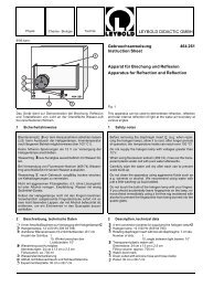
Lehrmodell einer Kompressionswärmepumpe auf Demonstrationstafel,<br />
als Luft/Wasser- oder Wasser/Wasser-Wärmepumpe<br />
verwendbar.<br />
Versuchsbeispiele:<br />
- Leistungszahl<br />
- Druck- und Temperaturmessung am Kältemittelkreislauf,<br />
Messungen zum Mollier- (h-, lg p)-Diagramm<br />
Zusammen mit Solarkollektor (<strong>389</strong> 50) und STE-Miniaturpumpe<br />
(579 22);<br />
- Modell eines Energiedaches<br />
Literatur: Buch "Energie 2" (599 651)<br />
1 Sicherheitshinweise<br />
5<br />
<strong>389</strong> <strong>521</strong><br />
15<br />
10 20<br />
5<br />
25<br />
0 30<br />
• Wärmepumpe immer vertikal aufbewahren, transportieren<br />
und betreiben; nach Kippen auf die Seite vor Inbetriebnahme<br />
mindestens 7 Stunden lang aufrecht stehen lassen.<br />
• Berührungsgefährliche Spannung im Kompressor-Stromkreis!<br />
Meßgeräte mit 4-mm-Buchsen nur über Sicherheitsexperimentierkabel<br />
(500 610 ff) und Meßanschlußkasten<br />
(502 05) anschließen.(s. Fig. 3.1)<br />
• Unter Druck stehenden Kältemittelkreislauf unter keinen<br />
Umständen zu öffnen versuchen!<br />
• Kompressor nicht thermisch isolieren! Überhitzungsgefahr!<br />
• Kupferrohre nicht als Griff benutzen! Verbiegungsgefahr!<br />
14<br />
4<br />
3<br />
2<br />
1<br />
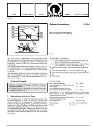
<strong>Gebrauchsanweisung</strong> <strong>389</strong> <strong>521</strong><br />
Instruction Sheet<br />
Wärmepumpe pT<br />
Heat Pump pT<br />
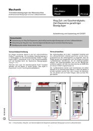
Fig. 1<br />
Teaching model of a compressor-type heat pump on demonstration<br />
panel, for use as air/water or water-water heat pump.<br />
Experiment examples:<br />
- Coefficient of performance<br />
- Measuring the pressure and temperature in the coolant<br />
circuit, measurements for Mollier (h, lg p) diagrams<br />
- Together with solar collector (<strong>389</strong> 50) and STE-miniature<br />
pump (579 22):<br />
- Model of a solar roof<br />
Literature: book "Experiments on energy 2" (599 651, in German)<br />
1 Safety notes<br />
• Always store, transport and operate the heat pump in a<br />
vertical position. If the apparatus is laid on its side, return it<br />
to the vertical and leave it in this position for at least 7<br />
hours before putting it into operation.<br />
• Dangerous contact voltages in compressor supply circuit!<br />
Connect measuring instruments with 4-mm sockets only<br />
via safety connecting leads (500 610 ff) and the measuring<br />
junction box (502 05); see Fig. 1.<br />
• The coolant circuit is pressurized. Do not attempt to open<br />
this circuit under any circumstances!<br />
• Do not thermally insulate the compressor; this can cause<br />
the device to overheat.<br />
• Do not carry the apparatus by the copper tubing: danger of<br />
bending!
P 1<br />
T 1<br />
2 Beschreibung Lieferumfang, technische Daten<br />
2.1 Beschreibung der Komponenten (Fig. 2)<br />
Kältemittel: R134a (FCKW-frei)<br />
� Kompressor 230 V; 50/60 Hz.<br />
Leistungsaufnahme ca. 130 W bei 50 Hz.<br />
� ausschwenkbare Stellfläche für rot-markierten Warmwasserbehälter<br />
� Verflüssiger, Innendurchmesser ca. 13 cm<br />
� Sammler/Reiniger<br />
� Expansionsventil, thermostatisch geregelt<br />
� Temperaturfühler des Expansionsventils, thermisch isoliert<br />
� Verdampfer, Innendurchmesser ca. 13 cm<br />
� ausschwenkbare Stellfläche für blau-markierten Kaltwasserbehälter<br />
� Rohrwindungen als elastische Verbindung zwischen Kompressor<br />
und Wärmetauscher<br />
� Druckwächter<br />
� Kunststoffhalter (2x) für Thermometer und Temperaturfühler,<br />
zum Anklemmen an Kupferrohre, jeweils bestehend<br />
aus doppelseitiger Klammer und Kunststoffrohr.<br />
� Kupfer-Meßschuh (2x) mit Klemmschrauben und Bohrungen,<br />
Ø 2 mm, zum Einstecken von Temperaturfühlern für<br />
Temperaturmessungen an den Kupferrohren des Kältemittelkreislaufs.<br />
� Manometer für die Niederdruckseite;<br />
innere Skala für Druckmessung von -1...+10 bar, äußerste<br />
Skala mit zugehöriger Taupunkttemperatur für R134a von<br />
-60 °C bis +40 °C.<br />
� Manometer für die Hochdruckseite; innere Skala: Druck<br />
von -1...+30 bar, äußerste Skala mit zugehöriger Taupunkttemperatur<br />
für R 134a von -60 °C bis + 85°C.<br />
Hinweis:<br />
Die beiden mittleren Temperaturskalen von � und � gelten für<br />
andere Kältemittel und sind daher bei dieser Wärmepumpe<br />
ohne Bedeutung.<br />
P 2<br />
T 2<br />
2<br />
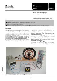
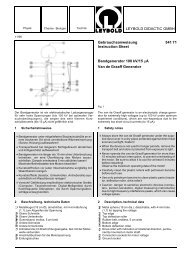
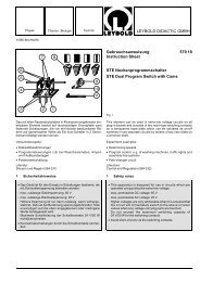
Fig. 2<br />
Wärmepumpe pT (<strong>389</strong> <strong>521</strong>) mit schematischer Darstellung<br />
der Funktionsteile<br />
Heat pump pT (<strong>389</strong> <strong>521</strong>) with schematic diagram of all<br />
functional components<br />
2 Description, scope of supply, technical data<br />
2.1 Description of components (Fig. 2)<br />
Coolant: R134a (CFC-free)<br />
� Compressor 230 V; 50/60 Hz.<br />
Power consumption approx. 130 W at 50 Hz.<br />
� Hinged support for water vessel with red mark<br />
� Liquefier, internal diameter approx. 13 cm<br />
� Collector/purifier<br />
� Expansion valve, thermostatically controlled<br />
� Temperature sensor for expansion valve, thermally<br />
insulated<br />
� Vaporizer, internal diameter approx. 13 cm<br />
� Hinged support for water vessel with blue mark<br />
� Spiral tubing as elastic connection between compressor<br />
and heat exchanger<br />
� Pressure switch<br />
� Plastic holders (2x) for thermometer and temperature sensor<br />
for clamping to copper tubing, each consisting of two-sided<br />
clamp and copper tube.<br />
� Copper measuring lug (2x) with terminal screws and holes<br />
2 mm dia. for inserting temperature sensors for temperature<br />
measurements at the copper tubes of the coolant circuit.<br />
� Manometer for the low-pressure side;<br />
inner scale for pressure measurement from -1...+10 bar,<br />
outer scale with corresponding dew-point temperature of<br />
R134a from -60 °C to +40 °C.<br />
� Manometer for high-pressure side; inner scale for pressure<br />
measurement from -1...+30 bar, outer scale with corresponding<br />
dew-point temperature of R134a from -60 °C to + 85°C.<br />
Note:<br />
the two middle temperature scales of � and � apply for other<br />
coolants, and are thus irrelevant for this heat pump.
Ohne Abbildung:<br />
Kaltwasserbehälter, 5 l, blau markiert<br />
mit zwei Schlaucholiven zum Anschluß eines externen Wasserkreislaufs;<br />
Innenskala mit Literteilung.<br />
Warmwasserbehälter, 5 l, rot markiert<br />
mit zwei Schlaucholiven zum Anschluß eines externen Wasserkreislaufs;<br />
Innenskala mit Literteilung.<br />
2 Schläuche, 1 m lang, Ø 6 mm<br />
Abmessungen:70 cm x 50 cm x 82 cm<br />
Masse: 30 kg<br />
2.2 Funktionsweise<br />
Eine Wärmepumpe entzieht einem Reservoir der Temperatur<br />
T1 Wärme und führt sie einem Reservoir der Temperatur T2 zu.<br />
Dadurch wird der Temperaturunterschied (T1-T2) zwischen beiden<br />
Reservoirs vergrößert. Der Wärmetransport geschieht<br />
über ein Kältemittel R134a , das beim Verdampfen Wärme aufnimmt<br />
und sie beim Kondensieren wieder abgibt.<br />
Die Wärmereservoirs sind gefüllte Wasserbehälter, in die die<br />
beiden "Wärmetauscher" � und � eintauchen.<br />
Das gasförmige Kältemittel wird vom Kompressor � komprimiert<br />
und dabei stark erhitzt. Es kühlt sich in der Kupferrohrschlange<br />
� des Verflüssigers ab und kondensiert, wobei es<br />
seine Kondensationswärme an das Wasser im Warmwasserbehälter<br />
abgibt.<br />
Das verflüssigte, aber noch mit Gasblasen durchsetzte Kältemittel<br />
wird im "Reiniger" � gefiltert. Dieser wirkt gleichzeitig als<br />
"Sammler": In seinem Innern bildet sich ein Flüssigkeitsspiegel,<br />
der eine blasenfreie Flüssigkeitszufuhr für das Expansionsventil<br />
� sicherstellt.<br />
Das Expansionsventil ist das Gegenstück zum Kompressor: Es<br />
dosiert die Kältemittelzufuhr zum Verdampfer �, wo das Kältemittel<br />
sich entspannt, verdampft, sich dabei stark abkühlt und<br />
so dem Kaltwasserreservoir Wärme entzieht. Das nun wieder<br />
gasförmige Kältemittel wird vom Kompressor angesaugt, wo<br />
der Kreislauf von vorne beginnt. Das Expansionsventil �<br />
schützt den Kompressor vor "Flüssigkeitsschlägen", d.h. Ansaugen<br />
flüssigen Kältemittels mit nachfolgender Zerstörung<br />
des Kompressors. Die Kältemittelzufuhr zum Verdampfer wird<br />
nämlich von einem Temperaturfühler � geregelt (daher auch<br />
die genauere Bezeichnung "thermostatisches Expansionsventil").<br />
Als Regelgröße dient die Temperaturdifferenz zwischen Einund<br />
Auslaßrohr des Verdampfers. Fällt diese unter einen bestimmten,<br />
am Expansionsventil fest eingestellten Wert-weil z.B.<br />
die Wärmezufuhr zum Verdampfer zu gering ist-, wird der Kältemittelnachschub<br />
gedrosselt.<br />
Der Druckwächter � schaltet den Kompressor ab, wenn der<br />
Druck auf der Verflüssigerseite 16 bar überschreitet (Einstellung<br />
auf der linken Skala ). Dies kann passieren, wenn der Verflüssiger<br />
� ohne Wasserreservoir betrieben und dadurch zu<br />
warm wird (T2 > 60 °C). Der Kompressor schaltet sich erst dann<br />
wieder ein, wenn der Druck um den auf der rechten Skala eingestellten<br />
Betrag (9 bar) unter den Abschaltdruck gefallen ist.<br />
Durch die Rohrwindungen � am Kompressor-Ein- und Auslaß<br />
wird verhindert, daß sich die Vibrationen des Kompressors auf<br />
das gesamte Gerät übertragen.<br />
3<br />
Not shown:<br />
Cold-water vessel, 5 l, with blue mark<br />
with two hose nipples for connecting an external water circuit;<br />
inner scale with liter divisions.<br />
Warm-water vessel, 5 l, with red mark<br />
with two hose nipples for connecting an external water circuit;<br />
inner scale with liter divisions.<br />
2 tubes, 1 m long, 6 mm dia.<br />
Dimensions: 70 cm x 50 cm x 82 cm<br />
Weight: 30 kg<br />
2.2 Function<br />
A heat pump withdraws heat from a reservoir with the temperature<br />
T1 and transports it to a reservoir with the temperature<br />
T2.<br />
As a result, the temperature difference (T1-T2) between the two<br />
reservoirs increases. The heat is transported by the coolant<br />
R134a, which absorbs heat through evaporation and releases it<br />
when it condenses.<br />
The heat reservoirs are vessels filled with water, in which the<br />
two "heat exchangers" � and � are immersed.<br />
The gaseous coolant is compressed in the compressor �,<br />
which heats it significantly. It is cooled in the spiral of copper<br />
tubing � of the liquefier and condenses, in the process transferring<br />
its heat of condensation to the water in the vessel.<br />
The liquified coolant still contains bubbles of gas, so it is filtered<br />
in the "purifier" �. This simultaneously functions as a<br />
"collector": it accumulates a level of liquid which ensures that<br />
the expansion valve � always receives a bubble-free liquid<br />
supply.<br />
The expansion valve is the counterpart of the compressor: it<br />
regulates the supply of coolant to the vaporizer �, where the<br />
coolant expands and evaporates. In the process it cools down<br />
rapidly, and thus withdraws heat from the cold-water vessel.<br />
The coolant, once more in the gaseous state, is drawn into the<br />
compressor, and the cycle begins anew. The expansion valve<br />
� protects the compressor from "liquid shocks", i.e. suction of<br />
liquid coolant, which would otherwise destroy the compressor.<br />
The supply of coolant to the vaporizer is regulated by a<br />
temperature sensor � (thus the more precise designation<br />
"thermostatic expansion valve").<br />
The temperature difference between the inlet and outlet tubes<br />
of the vaporizer serves as the controlled variable. If this value<br />
drops below a fixed value set at the expansion valve - e.g.<br />
because the supply of heat to the vaporizer is too low - the<br />
supply of coolant is reduced.<br />
The pressure switch � shuts down the compressor when the<br />
pressure on the liquefier side exceeds 16 bar (setting on the<br />
left-hand scale). This can occur when the liquefier � is operated<br />
without a water reservoir and thus becomes too warm<br />
(T2 > 60 °C). The compressor does not switch back on until the<br />
pressure drops below the shutoff pressure by the value set on<br />
the right side of the scale (9 bar).<br />
The spiral tubing sections � at the compressor inlet and outlet<br />
prevent the vibrations of the compressor from being transmitted<br />
to the entire apparatus.
3 Bedienung<br />
Zusätzlich erforderliche Geräte:<br />
Zur Temperaturmessung:<br />
Thermometer, Bereich 0 °C....50 °C, z.B.<br />
2 Temperaturfühler (666 193) mit digitalem Temperaturmeßgerät<br />
mit 4 Eingängen (666 210) , s. Fig. 3.1 oder<br />
2 Glasthermometer -10 °C....+50 °C (382 35)<br />
Zur qualitativen Temperaturanzeige: Satz Flüssigkristallfolien<br />
(382 93)<br />
Zur Messung der Kompressorleistung oder der aufgewandten<br />
elektrischen Arbeit:<br />
Entweder<br />
1 Wechselstromzähler (560 331)<br />
oder (s. Fig. 3.1)<br />
1 Leistungs- und Energiemesser (531 83) mit Meßanschlußkasten<br />
(502 05) und Sicherheitsexperimentierkabeln (500 610 ff)<br />
oder<br />
1 Spannungs- und 1 Strommesser (z.B. 2 x 531 911) mit<br />
Meßanschlußkasten (502 05) und Sicherheits-Experimentierkabeln<br />
(500 610 ff)<br />
1 Stoppuhr (z.B. 313 05)<br />
3.1 Versuchsaufbau<br />
Erforderliche Schlauchverbindungen zwischen Wasserbehälter<br />
und externem Wasserkreislauf herstellen, sonst jeweils obere<br />
und untere Schlaucholive jedes Behälters durch Schlauchstücke<br />
miteinander verbinden.<br />
Behälter bis zur 4-l-Markierung mit Wasser füllen, Stellflächen<br />
� und � ausschwenken, Wasserbehälter in Versuchsposition<br />
bringen und auf den wieder zurückgeschwenkten Stellflächen<br />
abstellen.<br />
Thermometerhalter an den Kupferrohren oberhalb des Verflüssigers<br />
� und des Verdampfers � festklemmen und Temperaturfühler<br />
in die Kunststoffröhrchen der Thermometerhalter einsetzen.<br />
Bei Benutzung eines Glasthermometers dieses anstelle<br />
des Kunststoffröhrchens in die Klammer vorsichtig(!) einschieben,<br />
nachdem die Klammer an das Kupferrohr angeklemmt<br />
wurde.<br />
W<br />
Ws<br />
10V<br />
30V<br />
1A 10² s<br />
3V<br />
100V 0,3A 3A 10s<br />
10³ s<br />
W<br />
1V<br />
300V 0,1A 10A 1s<br />
10 4 s<br />
Ws τ<br />
z<br />
Run<br />
10.00^=10V<br />
Stop<br />
U I<br />
Reset Output<br />
53183<br />
50205<br />
4 5<br />
3 6<br />
2<br />
7<br />
1<br />
8<br />
0<br />
9<br />
-1 10<br />
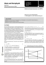
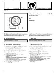
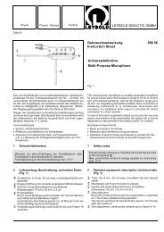
Fig. 3.1<br />
Wärmepumpe mit Geräten zur Temperatur- und Leistungsmessung<br />
4<br />
3 Operation<br />
Additionally required:<br />
For temperature measurement:<br />
Thermometer, range 0 °C....50 °C, e.g.<br />
2 temperature sensors (666 193) with digital thermometer with<br />
4 inputs (666 210) see Fig. 3.1 or<br />
2 glass thermometers -10 °C....+50 °C (382 35)<br />
For qualitative temperature indication: set of liquid crystal foils<br />
(382 93)<br />
For measuring the compressor power or the applied electrical<br />
work:<br />
Either<br />
1 alternating current meter (560 331)<br />
or (see Fig. 3.1)<br />
1 joule and wattmeter (531 83) with measuring junction box<br />
(502 05) and safety connecting leads (500 610 ff)<br />
or<br />
1 voltmeter and 1 ammeter (e.g. 2 x 531 911) with measuring<br />
junction box (502 05) and safety connecting leads (500 610 ff)<br />
1 stopclock (e.g. 313 05)<br />
3.1 Experiment setup<br />
Make the appropriate hose connections between the water<br />
vessel and the external water circuit; alternatively, connect the<br />
top and bottom hose nipples of each vessel together using<br />
sections of tubing.<br />
Fill each vessel with water up to the 4 l mark, fold up the<br />
supports � and �, place the water vessels in their experiment<br />
positions, then fold out the supports again and rest the water<br />
vessels on them.<br />
Attach the thermometer holders to the copper tubes above the<br />
liquefier � and the vaporizer � and insert the temperature<br />
sensors in the plastic tubes of the thermometer holders. When<br />
using a glass thermometer, carefully (!) insert it in the clamp in<br />
place of the plastic tube, but only after you attach the clamp to<br />
the copper tube.<br />
MIN MAX<br />
+<br />
U<br />
a<br />
-<br />
MAN<br />
COM<br />
T1-T2 MIN/MAX<br />
5s<br />
10s<br />
T1 2 T3 T4<br />
30s<br />
Ni Cr-Ni (-200...+1200°C) NTC (-20...+120°C) T1...T4 °C/°F/ K AUTOM.<br />
<strong>389</strong> <strong>521</strong><br />
15<br />
10 20<br />
5<br />
25<br />
0 30<br />
Fig. 3.1<br />
Heat pump with apparatus for measuring temperature and<br />
power
Fig. 3.2<br />
Temperaturverlauf im roten und blauen Wasserbehälter als<br />
Funktion der Zeit. Kompressorleistung: P = 127 W<br />
Temperature curves in red and blue water vessels as a<br />
function of time; compressor power: P = 127 W<br />
3.2 Bestimmung der Leistungszahl ε<br />
Wärmepumpe z.B. über Leistungs- und Energiemesser an das<br />
Netz anschließen. Meßanschlußkasten und Sicherheitsexperimentierkabel<br />
verwenden (s. Fig. 3.1)!<br />
Messung des Temperaturabfalls T1 (t) im blauen Wasserbehälter<br />
sowie des Temperaturanstiegs T2(t) im roten Wasserbehälter<br />
(Fig. 3.2) sowie der Leistungsaufnahme P des Kompressors.<br />
Während des Versuchs Wasser in beiden Wasserbehältern immer<br />
gut umrühren, ohne die Thermometer zu beschädigen:<br />
Zum Umrühren optimal geeignet: Kartoffelstampfer (Küchengerät)<br />
oder Eintauchpumpe 306 98.<br />
Auswertung<br />
Die Leistungszahl ε ist definiert als Verhältnis der Wärmemenge<br />
Δ Q, die von der Wärmepumpe pro Zeiteinheit Δt dem Warmwasserreservoir<br />
zugeführt wird, zur Leistung P des Kompressors:<br />
ε = ΔQ<br />
P Δt<br />
Dabei gilt<br />
ΔQ = c ⋅ m ⋅ ΔT2 mit<br />
c = spezifische Wärmekapazität von Wasser<br />
= 4,19 ⋅ 10 3 Ws kg -1 K -1<br />
m = Masse des Wassers = 4 kg<br />
Wenn Wärmeverluste in die Umgebung vernachlässigt werden,<br />
ist die Steigung<br />
ΔT2 (t)<br />
Δt<br />
einer Tangente an das T2 (t)-Diagramm der thermischen Leistung<br />
ΔQ<br />
Δt<br />
der Wärmepumpe proportional. Das Ergebnis der Auswertung<br />
zeigt Fig. 3.3. Die Leistungszahl ε (Δ T) nimmt mit wachsender-<br />
Temperaturdifferenz Δ T = T2-T1 zwischen Verflüssiger und<br />
Verdampfer ab (Fig. 3.3), weil das T2 (t)-Diagramm bei wachsender<br />
Temperaturdifferenz abflacht. Zu dieser Abflachung tragen<br />
bei hohen Temperaturen die Wärmeverluste durch Verdunsten<br />
des Wasers, Wärmeabstrahlung und -leitung des Kompressors<br />
und der Rohre zwischen Kompressor und Verflüssiger<br />
bei, deren Einfluß sich nicht quantitativ erfassen läßt.<br />
5<br />
Fig. 3.3<br />
Leistungszahl ε(ΔT) als Funktion der Temperaturdifferenz<br />
ΔT = T2 - T1 zwischen Warm- und Kaltwasserbehälter<br />
Coefficient of performance ε(ΔT) as a function of the<br />
temperature difference ΔT = T2 - T1 between the warm-water<br />
and cold-water vessels<br />
3.2 Determining the coefficient of performance ε<br />
Connect the heat pump to the mains e.g. via the joule and<br />
power meter. Use the measuring junction box and the safety<br />
connecting leads ( s. Fig. 3.1)!<br />
Measure the temperature drop T1 (t) in the blue water vessel<br />
and the temperature rise T2(t) in the red water vessel (Fig. 3.2)<br />
as well as the power consumption P of the compressor.<br />
During the experiment, stir the water in the two vessels well,<br />
being careful not to damage the thermometers; the most suitable<br />
stirring tools are a potato masher (from the kitchen) or the<br />
immersion pump 306 98.<br />
Evaluation<br />
The coefficient of performance ε is defined as the ratio of the<br />
amount of heat Δ Q supplied by the heat pump to the warmwater<br />
vessel per unit of time Δ t, and the power P of the<br />
compressor:<br />
ε = ΔQ<br />
P Δt<br />
where<br />
ΔQ = c ⋅ m ⋅ ΔT2 with<br />
c = specific heat capacity of water<br />
= 4,19 ⋅ 10 3 Ws kg -1 K -1<br />
m = mass of water = 4 kg<br />
When the ambient heat losses are ignored, the slope<br />
ΔT2 (t)<br />
Δt<br />
of a tangent to the T2 (t)-diagram is proportional to the thermal<br />
power<br />
ΔQ<br />
Δt<br />
of the heat pump. The result of the evaluation is shown in<br />
Fig. 3.3. The coefficient of performance ε (Δ T) decreases with<br />
the increasing temperature difference Δ T = T2-T1 between<br />
liquefier and vaporizer (Fig. 3.3), because the T2 (t) diagram<br />
levels off with increasing temperature difference. At high<br />
temperatures, factors contributing to this leveling-off include<br />
heat losses due to water evaporation, heat radiation and conduction<br />
of the compressor and the tubes between compressor and<br />
liquefier; their influence cannot be quantitatively determined<br />
here.
Optimierung der Leistungszahl<br />
a) Wasserbehälter und Rohrleitungen (nicht aber Kompressor!)<br />
thermisch isolieren (Schaumstoffstreifen).<br />
b) Kompressor vor Versuchsbeginn auf Betriebstemperatur<br />
bringen (ca. 10 Minuten laufen lassen), dann Wasser in<br />
den Behälter erneuern und Versuch starten.<br />
Optimizing the coefficient of performance<br />
a) Thermally insulate the water vessels and the tubes (but not<br />
the compressor!), e.g. with strips of foam rubber.<br />
b) Before starting the experiment, bring the compressor up to<br />
its operating temperature (let it run for approx. 10 minutes),<br />
then replace the water in the vessels and start the<br />
experiment.<br />
<strong>LEYBOLD</strong> <strong>DIDACTIC</strong> <strong>GMBH</strong> ⋅ Leyboldstrasse 1 ⋅ D-50354 Hürth ⋅ Phone (02233) 604-0 ⋅ Telefax (02233) 604-222 ⋅ Telex 17 223 332 LHPCGN D<br />
© by Leybold Didactic GmbH, Printed in the Federal Republic of Germany<br />
Technical alterations reserved

![[667 359] Labor-Refraktometer - LD DIDACTIC](https://img.yumpu.com/24788329/1/184x260/667-359-labor-refraktometer-ld-didactic.jpg?quality=85)