Welding symbols on drawings - .:YUSUF MANSUROGLU - P
Welding symbols on drawings - .:YUSUF MANSUROGLU - P
Welding symbols on drawings - .:YUSUF MANSUROGLU - P

Create successful ePaper yourself
Turn your PDF publications into a flip-book with our unique Google optimized e-Paper software.
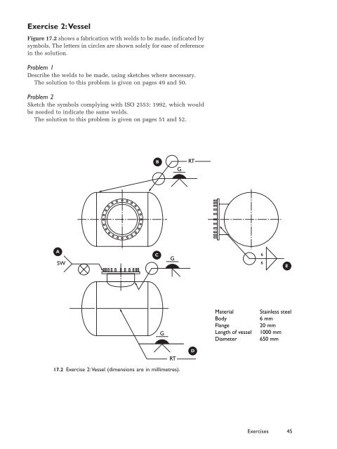
Exercise 2:Vessel<br />
Figure 17.2 shows a fabricati<strong>on</strong> with welds to be made, indicated by<br />
<str<strong>on</strong>g>symbols</str<strong>on</strong>g>. The letters in circles are shown solely for ease of reference<br />
in the soluti<strong>on</strong>.<br />
Problem 1<br />
Describe the welds to be made, using sketches where necessary.<br />
The soluti<strong>on</strong> to this problem is given <strong>on</strong> pages 49 and 50.<br />
Problem 2<br />
Sketch the <str<strong>on</strong>g>symbols</str<strong>on</strong>g> complying with ISO 2553: 1992, which would<br />
be needed to indicate the same welds.<br />
The soluti<strong>on</strong> to this problem is given <strong>on</strong> pages 51 and 52.<br />
A<br />
SW<br />
17.2 Exercise 2:Vessel (dimensi<strong>on</strong>s are in millimetres).<br />
B<br />
C<br />
G<br />
G<br />
RT<br />
G<br />
RT<br />
D<br />
Material<br />
Body<br />
Flange<br />
Length of vessel<br />
Diameter<br />
6<br />
6<br />
E<br />
Stainless steel<br />
6 mm<br />
20 mm<br />
1000 mm<br />
650 mm<br />
Exercises 45