Cabling Guidelines for INTRON-D - Industronic
Cabling Guidelines for INTRON-D - Industronic
Cabling Guidelines for INTRON-D - Industronic

You also want an ePaper? Increase the reach of your titles
YUMPU automatically turns print PDFs into web optimized ePapers that Google loves.
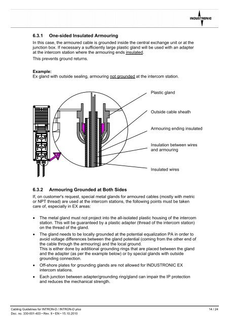
6.3.1 One-sided Insulated Armouring<br />
In this case, the armoured cable is grounded inside the central exchange unit or at the<br />
junction box. If necessary a sufficiently large plastic gland will be used with an adapter<br />
at the intercom station where the armouring ends insulated.<br />
This prevents ground returns.<br />
Example:<br />
Ex gland with outside sealing, armouring not grounded at the intercom station.<br />
6.3.2 Armouring Grounded at Both Sides<br />
Plastic gland<br />
Outside cable sheath<br />
Armouring ending insulated<br />
Insulation between wires<br />
and armouring<br />
Insulated wires<br />
If, on customer's request, special metal glands <strong>for</strong> armoured cables (mostly with metric<br />
or NPT thread) are used at the intercom stations, the following points must be taken<br />
care of, especially in EX areas:<br />
• The metal gland must not project into the all-isolated plastic housing of the intercom<br />
station. This will be guaranteed by a plastic adapter (thread of the intercom station)<br />
on the thread of the gland.<br />
• The gland needs to be locally grounded at the potential equalization PA in order to<br />
avoid voltage differences between the gland potential (coming from the other end of<br />
the cable through the armouring) and the local ground.<br />
This is either done by additional grounding rings that are placed between the gland<br />
and the adapter (as per the example below) or by special glands with outside<br />
grounding connection.<br />
• Off-shore plates <strong>for</strong> grounding glands are not allowed <strong>for</strong> INDUSTRONIC EX<br />
intercom stations.<br />
• Each junction between adapter/grounding ring/gland can impair the IP protection<br />
and reduces the mechanical strength.<br />
<strong>Cabling</strong> <strong>Guidelines</strong> <strong>for</strong> <strong>INTRON</strong>-D / <strong>INTRON</strong>-D plus 14 / 24<br />
Doc. no. 330-001-403 • Rev. 9 • EN • 15.10.2010