Cabling Guidelines for INTRON-D - Industronic
Cabling Guidelines for INTRON-D - Industronic
Cabling Guidelines for INTRON-D - Industronic

You also want an ePaper? Increase the reach of your titles
YUMPU automatically turns print PDFs into web optimized ePapers that Google loves.
<strong>Cabling</strong> <strong>Guidelines</strong> <strong>for</strong> <strong>INTRON</strong>-D /<br />
<strong>INTRON</strong>-D plus Systems<br />
Doc. no. 330-001-403 • Rev. 9 • EN • 15.10.2010
Table of Contents<br />
1 Introduction............................................................................................................ 3<br />
2 Abbreviations......................................................................................................... 3<br />
3 Applicable Documents / Standards ..................................................................... 3<br />
4 <strong>Cabling</strong> Scheme..................................................................................................... 4<br />
4.1 Example System ............................................................................................. 4<br />
5 Cable Types suitable <strong>for</strong> System Components................................................... 5<br />
5.1 Cables <strong>for</strong> Intercom Stations........................................................................... 5<br />
5.1.1 General <strong>Guidelines</strong>......................................................................................... 5<br />
5.1.2 Laying of Cables in Outdoor Areas ................................................................ 6<br />
5.1.3 Cable Laying Inside a Building ....................................................................... 7<br />
5.1.4 Cable Laying in Explosive Areas.................................................................... 7<br />
5.2 Loudspeaker Cables ....................................................................................... 8<br />
5.3 Cables <strong>for</strong> Flashing Beacons .......................................................................... 8<br />
5.4 Cables <strong>for</strong> 48 V / 60 V Battery Supplies.......................................................... 8<br />
5.5 Fiber-optic Cables........................................................................................... 9<br />
5.6 Antenna and Antenna Cables ......................................................................... 9<br />
6 Grounding concept / Potential Equalization ..................................................... 10<br />
6.1 Central Exchange Unit / System Voltage...................................................... 10<br />
6.2 Periphery / Grounding in Ex Areas ............................................................... 11<br />
6.3 Grounding of Armoured Cables .................................................................... 13<br />
6.3.1 One-sided Insulated Armouring.................................................................... 14<br />
6.3.2 Armouring Grounded at Both Sides ............................................................. 14<br />
6.3.3 Grounding by Off-Shore-Plates .................................................................... 16<br />
7 Wire Requirement Table <strong>for</strong> Digital Stations and Speakers ............................ 17<br />
7.1 Speech Applications ..................................................................................... 17<br />
7.2 Speech and Signal Applications ................................................................... 17<br />
7.3 Radio Applications ........................................................................................ 18<br />
7.4 Speaker <strong>Cabling</strong> ........................................................................................... 18<br />
8 Gland Sizes and Cable Data ............................................................................... 20<br />
8.1 Gland Sizes................................................................................................... 20<br />
8.2 Outside Diameter of Cables.......................................................................... 21<br />
8.3 Wire Diameter / Wire Cross Section ............................................................. 22<br />
8.4 Technical Data on Telecom Cables .............................................................. 22<br />
9 Conversion into Anglo-American Dimensions (AWG) ..................................... 23<br />
Document History and Imprint .................................................................................. 24<br />
<strong>Cabling</strong> <strong>Guidelines</strong> <strong>for</strong> <strong>INTRON</strong>-D / <strong>INTRON</strong>-D plus 2 / 24<br />
Doc. no. 330-001-403 • Rev. 9 • EN • 15.10.2010
1 Introduction<br />
This document outlines the general rules <strong>for</strong> the cabling of communication and public<br />
address systems of types <strong>INTRON</strong>-D and in particular <strong>INTRON</strong>-D plus from<br />
INDUSTRONIC.<br />
2 Abbreviations<br />
EL Public addressing<br />
e.g. one-way communication within speaker circuits (= PA<br />
technology) or to intercom stations without talk-back facility<br />
TC Telecome.g.<br />
TC cable = telecom cable<br />
INTERCOM Generic term <strong>for</strong> communication techniques,<br />
e.g two-way communication, party line, telephony, radio etc.<br />
<strong>INTRON</strong>-D / Fully digital INDUSTRONIC system<br />
<strong>INTRON</strong>-D plus<br />
ISDN Integrated Services Digital Network = hardware plat<strong>for</strong>m <strong>for</strong><br />
intercom devices<br />
LINE Pair of wires <strong>for</strong> the transmission of digitalized voice /control<br />
signals and phantom powering of an intercom station<br />
LK Speaker circuit<br />
OFF-SHORE Special technology <strong>for</strong> installation on drilling rigs with common<br />
grounding plate <strong>for</strong> cable gland<br />
PA Potential equalization<br />
PE Protection Earth = Schutzerde<br />
WL Two-way communication (half duplex), i.e. pressing the talk<br />
key <strong>for</strong> talking, releasing the key <strong>for</strong> listening<br />
3 Applicable Documents / Standards<br />
System documentation <strong>for</strong> the reference project (if any)<br />
Wiring calculation guidelines <strong>for</strong> analog systems: 330-001-015<br />
VDE 0100: <strong>Guidelines</strong> <strong>for</strong> the erection of high voltage systems up to 1000V<br />
VDE 0165; EN 60079-14: Erecting electric systems in hazardous areas<br />
IEC / EN 60079- ... Ex Protection types<br />
VDE 0800 Intercom technology<br />
VDE 0815 Cables <strong>for</strong> installation in telecom and data processing systems<br />
VDE 0816 Outdoor cables <strong>for</strong> telecom systems<br />
<strong>Cabling</strong> <strong>Guidelines</strong> <strong>for</strong> <strong>INTRON</strong>-D / <strong>INTRON</strong>-D plus 3 / 24<br />
Doc. no. 330-001-403 • Rev. 9 • EN • 15.10.2010
4 <strong>Cabling</strong> Scheme<br />
In order to guarantee highest safety and availability of the INDUSTRONIC intercom<br />
systems, cables to intercom stations and centrally supplied loudspeaker groups etc.<br />
are generally laid by starting at the central exchange unit.<br />
Only the cross connections between parallel loudspeakers and the connections of a<br />
station's subcomponents are laid on site. Junction boxes <strong>for</strong> the cabling will be applied<br />
on customer's request.<br />
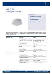
4.1 Example System<br />
The following diagram is a typical wiring diagram (branch scheme) of a combined<br />
digital intercom system with public address facility:<br />
1DES03<br />
1MH14<br />
1DES02 +<br />
2*16DET01<br />
12DT00x 6DA00x AXA311 6DX00x CWB-ATEX 4*<br />
DSP25EExmN<br />
6DWS01 +2*HS15EEmN +HS15EEmN<br />
+CWB-ATEX<br />
Number of necessary wires<br />
The number of wires <strong>for</strong> digital intercom stations of <strong>INTRON</strong>-D / <strong>INTRON</strong>-D plus<br />
systems is calculated as follows:<br />
• 2 basic wires (a/b lines including phantom powering)<br />
• + 2 additional supply wires if booster amplifiers, ancillary units or desktop intercom<br />
stations with more than 2 keypads are employed (see chapter 7)<br />
• + 2 additional supply wires <strong>for</strong> flashing beacons<br />
The number of wires <strong>for</strong> analog intercom stations of <strong>INTRON</strong>-D / <strong>INTRON</strong>-D plus<br />
systems is calculated as follows:<br />
• 4 basic wires (+/- <strong>for</strong> Spannungsversorgung, a/b für NF),<br />
• + 1 supply wire <strong>for</strong> the booster amplifier (included in the standard calculation)<br />
• + 1 wire <strong>for</strong> each installed key at the intercom station<br />
The central exchange unit of the system shown above consists of:<br />
<strong>Cabling</strong> <strong>Guidelines</strong> <strong>for</strong> <strong>INTRON</strong>-D / <strong>INTRON</strong>-D plus 4 / 24<br />
Doc. no. 330-001-403 • Rev. 9 • EN • 15.10.2010
• Central exchange cabinet 1 with exchange facility<br />
• Central exchange cabinet 2 with power supply and battery backup<br />
The following peripheral units are used:<br />
• Station 1: Digital flush-mounted intercom station with 32 keys<br />
• Station 2: Digital desktop intercom station with 12 keys, dial keypad, display and<br />
wall socket<br />
• Station 3: Digital outdoor intercom station with 6 keys<br />
• Station 4: Analog explosion-proof intercom station with 2 keys, booster amplifier<br />
and 2 explosion-proof loudspeakers<br />
• Station 5: Digital explosion-proof intercom station with 6 keys, booster amplifier, 1<br />
explosion-proof loudspeaker and flashing beacon with junction box<br />
• H1: Explosion-proof flashing beacon<br />
• LK1: 4x Explosion-proof loudspeakers (central power supply, local grounding)<br />
5 Cable Types suitable <strong>for</strong> System Components<br />
Depending on the various components of the communication system, different cable<br />
types are applied.<br />
Please, note that cables <strong>for</strong> the periphery of the communication system must not be<br />
laid next to high-voltage cables, power cables or cables with large RF or harmonics<br />
shares (e.g. <strong>for</strong> rotary current thyristor drives).<br />
There should be a minimum distance of 30 cm to such cables.<br />
5.1 Cables <strong>for</strong> Intercom Stations<br />
5.1.1 General <strong>Guidelines</strong><br />
Cables which connect intercom stations with the central exchange unit must principally<br />
have twisted pair wires or star quad wires. Thus, possible interferences and alternating<br />
fields cannot impair the quality of the communication.<br />
Normally, further protection of the cables is not necessary. For guidelines on armoured<br />
cables, please refer to item 6.3.<br />
Cables are laid according to local rules, e.g. on flat beds or in conduits.<br />
Depending on the lengths of the cables, some wires <strong>for</strong> intercom stations may have to<br />
be connected in parallel. Regarding digital intercom stations, further instructions on this<br />
subject can be taken from chapter 7 and regarding analog stations from document no.<br />
330-001-015.<br />
<strong>Cabling</strong> <strong>Guidelines</strong> <strong>for</strong> <strong>INTRON</strong>-D / <strong>INTRON</strong>-D plus 5 / 24<br />
Doc. no. 330-001-403 • Rev. 9 • EN • 15.10.2010
5.1.2 Laying of Cables in Outdoor Areas<br />
For outdoor intercom stations, telecom cables are applied usually.<br />
INDUSTRONIC recommends the A2Y(L)2Y .... x2x0,8 ST III Bd cable types. These are<br />
designed <strong>for</strong> industrial ambient conditions and are mechanically stable.<br />
Cable Structure A2Y(L)2Y ... (according to DIN VDE 0816):<br />
Outer sheath: PE (rein<strong>for</strong>ced)<br />
Static screen: plastic covered aluminium band<br />
k t t ffb hi ht t<br />
Stranding: star quad twisting<br />
Plastic foil<br />
Conductor: bare copper wire<br />
Insulation of the wires: polyethelene<br />
Please, note that, with star quad twisting, pairs are <strong>for</strong>med by opposite wires (not by<br />
neighbouring ones).<br />
Marking <strong>for</strong> unit stranded cables A2Y(L)2Y ... according to VDE 0816:<br />
The wires of a quad are marked by rings. Pairs (branches) are <strong>for</strong>med by opposite<br />
wires.<br />
Branch 1<br />
Star quad a - wire (without ring)<br />
b - wire<br />
Branch 2<br />
a - wire<br />
b - wire<br />
Five star quads with differently colored wires <strong>for</strong>m one bundle.<br />
Quad 1: red<br />
Quad 2: green<br />
Quad 3: grey<br />
Quad 4: yellow<br />
Quad 5: white<br />
Bundles where the counting starts anew are marked by red helixes.<br />
For further technical details, please, refer to chapter 8.<br />
<strong>Cabling</strong> <strong>Guidelines</strong> <strong>for</strong> <strong>INTRON</strong>-D / <strong>INTRON</strong>-D plus 6 / 24<br />
Doc. no. 330-001-403 • Rev. 9 • EN • 15.10.2010
5.1.3 Cable Laying Inside a Building<br />
Inside buildings, also telecom indoor cables of the J-Y(St)Y ... x2x0,8 Lg type are<br />
applied.<br />
Cable structure J-Y(ST)Y... (according to DIN VDE 0815):<br />
Outside sheath: PVC<br />
Marking <strong>for</strong> telecom indoor cables J-Y(ST)Y... according to VDE 0815:<br />
The wires are distinguished by the colour of their insulation:<br />
Two-paired installation cables:<br />
1. pair: a - wire red, b - wire black<br />
2. pair: a - wire white, b - wire yellow<br />
Four- or multi-paired installation cables:<br />
a - wire of the first pair in each layer red, of the other pairs white<br />
b - wire blue, yellow, green, brown, black being continuously repeated<br />
For further technical details, please refer to chapter 8.<br />
Static screen: plastic covered aluminium foil with<br />
additional Cu wire<br />
Stranding: twisted pairs<br />
Plastic foil<br />
Insulation of the wires: PVC<br />
Conductor: bare copper wire<br />
5.1.4 Cable Laying in Explosive Areas<br />
The EN/IEC 60079-14:2008 standard requires that fixed laid cables contain embedded<br />
extruded material and non-hygroscopic fillers. When laying cables outdoors,<br />
A2YF(L)2Y .... x2x0,8 ST III Bd telecom cable types can be used in the Ex zones 1 and<br />
2, provided that additional measures are taken to prevent a potential flame<br />
propagation, e.g. installing cables in trenches filled with sand (see EN/IEC 60079-14,<br />
chapter 9).<br />
As an alternative, telecom cables with additional flame-retardant outer sheath having<br />
flame propagation characteristics as per IEC 60332-1 can be installed in explosive<br />
areas, e.g. A2YF(L)2YY... .<br />
<strong>Cabling</strong> <strong>Guidelines</strong> <strong>for</strong> <strong>INTRON</strong>-D / <strong>INTRON</strong>-D plus 7 / 24<br />
Doc. no. 330-001-403 • Rev. 9 • EN • 15.10.2010
According to EN/IEC 60079-14:2008 free wires ending in the Ex “e” compartments of<br />
devices installed in explosive areas must be properly insulated using terminals suitable<br />
<strong>for</strong> this type of ignition protection. Using only an insulating tape <strong>for</strong> insulation is not<br />
permitted. Cables leading to DX or DXG type intercom stations must have appropriate<br />
dimensions to connect all wires to the existing terminals. Two cores of same wire type<br />
and diameter can be connected to one terminal up to a cross section of 1 mm 2 .<br />
5.2 Loudspeaker Cables<br />
Loudspeaker applications in industries use the 100 V technology. Thus, high<br />
loudspeaker powers can be supplied at low losses over large distances.<br />
In most cases, outside power cables of the type NYY-0 2x1,5² (see 5.2) are used, as<br />
the loudspeakers are all-insulated or separately connected to the local PA.<br />
If a cable of the type NYY-J 3x1,5² with a protective conductor is used, the conductor<br />
needs to be insulated on both sides or cut off with the cable's outside insulation.<br />
For connecting an intercom station with booster amplifier to an additional loudspeaker,<br />
also telecom cables might be used (please, refer to 5.1). In this case, please, ensure a<br />
corresponding electric strength of >200V.<br />
Regarding the loudspeaker cabling, observe the corresponding grounding regulations<br />
(item 6.2 periphery / grounding in EX areas).<br />
5.3 Cables <strong>for</strong> Flashing Beacons<br />
For flashing beacons with 48V/60V technology, both telecom cables (please refer to<br />
5.1) and power cables (please refer to 5.2) can be used.<br />
For flashing beacons that are relay-driven by the central exchange unit, power cables<br />
are preferable. For flash beacons being operated with mains voltage (115V/230V),<br />
power cables are obligatory.<br />
5.4 Cables <strong>for</strong> 48 V / 60 V Battery Supplies<br />
Due to the possibly high short-circuit current, increased demands have to be met<br />
concerning the cabling of battery cabinets or racks.<br />
Feed lines of battery blocks on separate battery racks have to be bipolarly protected<br />
directly at the battery block (e.g. by a HRC fuse) taking into account the necessary<br />
distance to the batteries. Between battery and fuse, cables have to be laid which are<br />
short circuit proof and resistant to oil and acid.<br />
Connecting cables between power supply cabinets and other central exchange<br />
cabinets are protected inside the power supply cabinets. It is not necessary to protect<br />
the other ends of the cables.<br />
For battery blocks the cable cross section depends on the current and the fuse<br />
protection. Typically, <strong>for</strong> battery capacities up to 65 Ah and line lengths of up to 10 m<br />
cables of type NYY-O 0 4x16² are used and <strong>for</strong> battery blocks up to 120 Ah, the type<br />
NYY-0 4x35² or NYY-0 4x25².<br />
The cable types <strong>for</strong> higher battery capacities or longer lines will be indicated in the<br />
corresponding system documentation.<br />
<strong>Cabling</strong> <strong>Guidelines</strong> <strong>for</strong> <strong>INTRON</strong>-D / <strong>INTRON</strong>-D plus 8 / 24<br />
Doc. no. 330-001-403 • Rev. 9 • EN • 15.10.2010
5.5 Fiber-optic Cables<br />
For <strong>INTRON</strong>-D intercom systems INDUSTRONIC offers <strong>INTRON</strong>-D / <strong>INTRON</strong>-D plus<br />
components which serve to set up subcentrals (satellites) or couple several central<br />
exchange units. These components are connected by fibre-optic cables.<br />
Electro-magnetic interferences can be excluded on such cables. Existing fibres, e.g. at<br />
crane applications, can be made use of.<br />
The following items have to be observed:<br />
For each route you need two fibres which must be exclusively available <strong>for</strong> the<br />
<strong>INTRON</strong>-D / <strong>INTRON</strong>-D plus systems.<br />
• Use optic fibres of gradient type 50/125μm or 62.5/125μm, alternatively singlemode<br />
fibers 9/125μm, suitable <strong>for</strong> the component<br />
• Use only one fiber type <strong>for</strong> one connection.<br />
• Max. cable length 3 km per fiber<br />
• Max. allowed attenuation
6 Grounding concept / Potential Equalization<br />
6.1 Central Exchange Unit / System Voltage<br />
Grounding serves as protection from overvoltage in direct current and low frequency<br />
areas.<br />
A central exchange cabinet with live components requires all electrically conductive<br />
parts to be properly grounded.<br />
Furthermore, grounding is essentially necessary in order to "shield" the complete<br />
system effectively.<br />
Consequently, all side panels, roofs and doors of INDUSTRONIC cabinets are already<br />
electrically connected as a standard.<br />
There<strong>for</strong>e, on site you only have to shunt the complete cabinet to the corresponding<br />
ground potential. This saves time during installation and rules out possible sources of<br />
trouble.<br />
Connect the equipotential busbar in the installation room via a grounding line with the<br />
central grounding point in the cabinet.<br />
The central grounding point in the cabinet is marked .<br />
The grounding line is required according to general regulations to have at least a<br />
conductor cross-section as indicated in the following table:<br />
Equipotential busbar<br />
installation room<br />
From to Distance<br />
Grounding point<br />
central exchange<br />
cabinet<br />
< 10 m<br />
> 10 m<br />
Conductor crosssection<br />
mm² AWG<br />
Note: AWG means "American Wire Gage" and is generally used in North America <strong>for</strong><br />
measuring conductors. Those values are indicated as in<strong>for</strong>mation only.<br />
INDUSTRONIC central exchange cabinets generally have to be connected to the local<br />
system ground (protective ground PE). Every cabinet has a grounding knot.<br />
As a rule, the system voltage <strong>for</strong> INDUSTRONIC intercom systems is 60VDC or<br />
48VDC.<br />
This system voltage is not grounded in order to avoid parasitic inductions and ground<br />
returns. In case overvoltage protection modules are used <strong>for</strong> connected station lines,<br />
the negative pole of the supply voltage must be grounded. Otherwise, there is the<br />
danger that the system voltage separates from the ground potential releasing the<br />
overvoltage arresters. In order to exclude interferences the system voltage is<br />
connected to ground via an inductance.<br />
INDUSTRONIC does not use function grounds as described in VDE 0800.<br />
<strong>Cabling</strong> <strong>Guidelines</strong> <strong>for</strong> <strong>INTRON</strong>-D / <strong>INTRON</strong>-D plus 10 / 24<br />
Doc. no. 330-001-403 • Rev. 9 • EN • 15.10.2010<br />
10<br />
16<br />
6<br />
4
6.2 Periphery / Grounding in Ex Areas<br />
According to VDE 0100 all (not all-insulated) stationary electrical devices with metal<br />
housings must be grounded.<br />
Regarding the peripheral units from INDUSTRONIC, this applies only to metal<br />
loudspeakers, flash lamps and junction boxes and possible project-specific special<br />
units.<br />
INDUSTRONIC intercom stations have a protective insulation and do not provide of a<br />
grounding connection. If a component that must be grounded, e.g. a metal<br />
loudspeaker, has to be connected to an intercom station, the loudspeaker will be<br />
locally grounded (potential equalization PA). Flashing beacons and metal loudspeakers<br />
that are supplied by the central exchange unit as well as noise absorbing hoods will be<br />
locally grounded, too.<br />
Attention:<br />
In EX areas all metal parts (also non-electrical ones) from a certain size upward are on<br />
site electrically connected to the potential equalization of the respective area.<br />
Even a small potential difference of only some V could already cause a spark which<br />
then could lead to an explosion (please, also refer to 6.3 “Grounding of Armoured<br />
Cables”).<br />
However:<br />
PA areas set by the customers must remain isolated from each other!<br />
There<strong>for</strong>e, it must be taken care that the armourings or shieldings of cables<br />
between different PA areas are insulated at least at one end!<br />
Otherwise, equalizing currents of up to several kilo Ampère could arise there!<br />
Additionally, there could emerge interferences in the cable that would impair the quality<br />
of the communication.<br />
Thus, INDUSTRONIC recommends not to ground the armouring or shielding!<br />
<strong>Cabling</strong> <strong>Guidelines</strong> <strong>for</strong> <strong>INTRON</strong>-D / <strong>INTRON</strong>-D plus 11 / 24<br />
Doc. no. 330-001-403 • Rev. 9 • EN • 15.10.2010
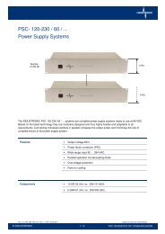
System example:<br />
The following diagram shows a branch scheme of a system with various PA areas.<br />
The armourings or shieldings of the cables must in any case end insulated at the<br />
marked places!<br />
The PA areas are defined by the customer and have to be communicated to<br />
INDUSTRONIC ® <strong>for</strong> the cable engineering.<br />
.<br />
Central exchange outside the PA areas. Junction box of PA area A with cables to<br />
Cabinet grounded to the system ground, other PA areas.<br />
outgoing cable not grounded.<br />
The armourings/shieldings of the cables<br />
must end insulated here!<br />
Off-shore technology is not allowed here!<br />
Off-shore junction boxes of the PA areas B and C with cables locally grounded<br />
inside the respective PA area.<br />
All metal parts of one area are electrically connected.<br />
There must not flow any equalizing currents between the PA areas A, B, C!<br />
<strong>Cabling</strong> <strong>Guidelines</strong> <strong>for</strong> <strong>INTRON</strong>-D / <strong>INTRON</strong>-D plus 12 / 24<br />
Doc. no. 330-001-403 • Rev. 9 • EN • 15.10.2010
6.3 Grounding of Armoured Cables<br />
On request of the customer, armoured cables may be used in certain cases.<br />
Armouring represents a mechanical protection of the cable but can also be used <strong>for</strong><br />
shielding.<br />
Potential equalization via the armouring cannot be recommended but should be<br />
measured or dimensioned in each particular case and belongs to the responsibility of<br />
the customer.<br />
If the armouring is used as electrical shielding, the shielding should be grounded at one<br />
side only to protect against ground returns and equalizing currents, i.e. the armouring<br />
should end insulated in a plastic gland. INDUSTRONIC does not recommend the<br />
armouring's grounding at both sides. This would be allowed only within a PA area and<br />
could cause interferences of the communication quality.<br />
Please, also note the instructions of item 6.2!<br />
If special metal armoured glands as per customer's request are used, the following<br />
parameters always have to be indicated when selecting the glands:<br />
• Outside cable diameter<br />
• Outside diameter of the armouring<br />
• Desired type of thread<br />
• Ambient conditions (range of temperatures, IP protection degree)<br />
• Industrial or Ex version (Ex-d, Ex-e)<br />
• Sealing:<br />
- only outside sheath<br />
- only inside sheath<br />
- outside and inside sheath<br />
- outside sheath and lead cover<br />
• Armouring type and wire strength<br />
The following types of armouring are available:<br />
• Steel tape armouring (DSTA)<br />
• Single wire armouring (SWA)<br />
• Wire braid armouring (wire braid)<br />
• Aluminium tape armouring (AWA + ASA)<br />
Please, note that bulky glands might perhaps allow only one entry at each side of the<br />
housing as the distance between the glands is predefined by the prepared thread inset<br />
plate.<br />
<strong>Cabling</strong> <strong>Guidelines</strong> <strong>for</strong> <strong>INTRON</strong>-D / <strong>INTRON</strong>-D plus 13 / 24<br />
Doc. no. 330-001-403 • Rev. 9 • EN • 15.10.2010
6.3.1 One-sided Insulated Armouring<br />
In this case, the armoured cable is grounded inside the central exchange unit or at the<br />
junction box. If necessary a sufficiently large plastic gland will be used with an adapter<br />
at the intercom station where the armouring ends insulated.<br />
This prevents ground returns.<br />
Example:<br />
Ex gland with outside sealing, armouring not grounded at the intercom station.<br />
6.3.2 Armouring Grounded at Both Sides<br />
Plastic gland<br />
Outside cable sheath<br />
Armouring ending insulated<br />
Insulation between wires<br />
and armouring<br />
Insulated wires<br />
If, on customer's request, special metal glands <strong>for</strong> armoured cables (mostly with metric<br />
or NPT thread) are used at the intercom stations, the following points must be taken<br />
care of, especially in EX areas:<br />
• The metal gland must not project into the all-isolated plastic housing of the intercom<br />
station. This will be guaranteed by a plastic adapter (thread of the intercom station)<br />
on the thread of the gland.<br />
• The gland needs to be locally grounded at the potential equalization PA in order to<br />
avoid voltage differences between the gland potential (coming from the other end of<br />
the cable through the armouring) and the local ground.<br />
This is either done by additional grounding rings that are placed between the gland<br />
and the adapter (as per the example below) or by special glands with outside<br />
grounding connection.<br />
• Off-shore plates <strong>for</strong> grounding glands are not allowed <strong>for</strong> INDUSTRONIC EX<br />
intercom stations.<br />
• Each junction between adapter/grounding ring/gland can impair the IP protection<br />
and reduces the mechanical strength.<br />
<strong>Cabling</strong> <strong>Guidelines</strong> <strong>for</strong> <strong>INTRON</strong>-D / <strong>INTRON</strong>-D plus 14 / 24<br />
Doc. no. 330-001-403 • Rev. 9 • EN • 15.10.2010
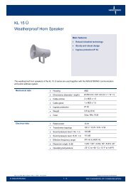
Example:<br />
EX gland with inside and outside sealing <strong>for</strong> steel wire armoured cables, locally<br />
grounded by a separate grounding ring and grounding wire.<br />
Plastic adapter M25<br />
Grounding connection of the<br />
armouring by separate grounding<br />
Armouring gland<br />
Armouring connected to the<br />
gland by a cone<br />
Steel wire armoured cable<br />
<strong>Cabling</strong> <strong>Guidelines</strong> <strong>for</strong> <strong>INTRON</strong>-D / <strong>INTRON</strong>-D plus 15 / 24<br />
Doc. no. 330-001-403 • Rev. 9 • EN • 15.10.2010
6.3.3 Grounding by Off-Shore-Plates<br />
If armoured cables are used in connection with junction boxes, the metal glands of the<br />
incoming and outgoing cables are electrically connected with each other by so-called<br />
off-shore plates at the junction boxes and are connected to the local ground (potential<br />
equalization). This is admissible only within each PA area.<br />
Please, also note our instructions as per item 6.2!<br />
Off-shore plates are brass plates in the junction box housing with cut threads where the<br />
glands are screwed in and thus grounded.<br />
Off-shore plates must not be inserted into INDUSTRONIC EX intercom stations!<br />
Example:<br />
Plastic junction box with off-shore technology, metal EX armouring glands, grounded<br />
by an inserted off-shore plate.<br />
Grounding connection of the off-shore<br />
plate, e.g. to the grounding terminal and,<br />
by another gland, directly to the local<br />
ground (PA)<br />
Off-Shore plate (brass)<br />
Armouring gland, screwed through<br />
the housing into the off-shore plate<br />
Steel wire armoured cable<br />
<strong>Cabling</strong> <strong>Guidelines</strong> <strong>for</strong> <strong>INTRON</strong>-D / <strong>INTRON</strong>-D plus 16 / 24<br />
Doc. no. 330-001-403 • Rev. 9 • EN • 15.10.2010
7 Wire Requirement Table <strong>for</strong> Digital Stations and<br />
Speakers<br />
Wires <strong>for</strong> additional power supply<br />
For the connection of a digital intercom station, two wires are normally required.<br />
However, we recommend to lay at least 4 wires to all intercom stations, even if they<br />
should not yet be necessary at the time of installation.<br />
Within a distance of 2 km to the central exchange unit, modular desktop intercom<br />
stations and flush-mounted intercom stations with up to 2 keypads can be operated via<br />
two wires. If the distance is greater or if there are more than 2 keypads, two further<br />
wires are necessary <strong>for</strong> the power supply. If the relevant station has a booster<br />
amplifier, the electronics can be fed via the amplifier’s supply lines.<br />
Safety note:<br />
To avoid breakdown times and subsequent costs because of broken wires, we suggest<br />
to provide additional spare wires, especially <strong>for</strong> long distances (e.g. > 1000 meters).<br />
Since the power consumption of an intercom station receiving continuous tone signals<br />
is higher than when receiving voice signals, the wire requirements are calculated<br />
separately <strong>for</strong> both cases.<br />
7.1 Speech Applications<br />
Depending on the length of cables the number of wires is to be calculated as follows:<br />
Wire diameter = 0.8 mm:<br />
System Voltage Cable length Wires <strong>for</strong> a/b<br />
line<br />
Wires <strong>for</strong><br />
additional<br />
amplifier<br />
60 V DC 0 to 1500 m 2 2 4<br />
1500 to 4000 m 2 4 6<br />
68 V DC 0 to 2000 m 2 2 4<br />
2000 to 4000 m 2 4 6<br />
7.2 Speech and Signal Applications<br />
Total<br />
number<br />
of wires<br />
Depending on the length of cables the number of wires is to be calculated as follows:<br />
Wire diameter = 0.8 mm:<br />
System Voltage Cable length Wires <strong>for</strong> a/b<br />
line<br />
Wires <strong>for</strong><br />
additional<br />
amplifier<br />
Total<br />
number<br />
of wires<br />
60 V DC 0 to 500 m 2 2 4<br />
500 to 1300 m 2 4 6<br />
1300 to 2500 m 2 6 8<br />
68 V DC 0 to 700 m 2 2 4<br />
700 to 1800 m 2 4 6<br />
1800 to 2900 m 2 6 8<br />
<strong>Cabling</strong> <strong>Guidelines</strong> <strong>for</strong> <strong>INTRON</strong>-D / <strong>INTRON</strong>-D plus 17 / 24<br />
Doc. no. 330-001-403 • Rev. 9 • EN • 15.10.2010
7.3 Radio Applications<br />
Wire diameter: = 0.8 mm:<br />
System voltage Cable length Wires <strong>for</strong> a/b<br />
line<br />
Wires <strong>for</strong><br />
power supply<br />
Total<br />
number<br />
of wires<br />
60 V DC 0 to 500 m 2 2 4<br />
500 to 1300 m 2 4 6<br />
1300 to 2500 m 2 6 8<br />
68 V DC 0 to 700 m 2 2 4<br />
700 to 1800 m 2 4 6<br />
1800 to 2900 m 2 6 8<br />
110 / 230 V AC 0 to 2500 m 2 * 2<br />
*) The voltage is supplied in a decentralised way and according to the local regulations.<br />
7.4 Speaker <strong>Cabling</strong><br />
<strong>Cabling</strong> between central exchange unit and speakers or speaker groups.<br />
Depending on the length of cable and the power, the cross-section of wires is<br />
calculated as follows:<br />
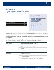
-3dB power loss <strong>for</strong> speech and public address applications<br />
Power to transfer<br />
Cable length 30W 50W 100W 150W 250W wire of<br />
0 to 700m 1.5mm² 1.5mm² 1.5mm² 1.5mm² 1.5mm²<br />
700 to 1000m 1.5mm² 1.5mm² 1.5mm² 1.5mm² 2.5mm²<br />
1000 to 1900m 1.5mm² 1.5mm² 1.5mm² 2.5mm² 4mm²<br />
1900 to 2800m 1.5mm² 1.5mm² 2.5mm² 4mm² 6mm²<br />
2800 to 4000m 1.5mm² 1.5mm² 4mm² 6mm² 10mm² Cross-section<br />
A power loss of -3dB with speech applications is only audible in the direct comparison<br />
and corresponds to a volume difference of -3dB. For alarm applications we recommend<br />
a power loss of no more than -2dB.<br />
<strong>Cabling</strong> <strong>Guidelines</strong> <strong>for</strong> <strong>INTRON</strong>-D / <strong>INTRON</strong>-D plus 18 / 24<br />
Doc. no. 330-001-403 • Rev. 9 • EN • 15.10.2010
Cable diagram <strong>for</strong> –3dB power loss<br />
Cable length [m]<br />
4000<br />
3500<br />
3000<br />
2500<br />
2000<br />
1500<br />
1000<br />
500<br />
0<br />
20 30 40 50 60 70 80 90 100 110 120 130 140 150 160 170 180 190 200 210 220 230 240 250 260 270 280 290 300<br />
Pow er to transfer [W att]<br />
-2dB power loss <strong>for</strong> emergency and alarm application<br />
Power to transfer<br />
Cable length 30W 50W 100W 150W 250W<br />
0 to 400m 1.5mm² 1.5mm² 1.5mm² 1.5mm² 1.5mm²<br />
400 to 1100m 1.5mm² 1.5mm² 1.5mm² 2.5mm² 4mm²<br />
1100 to 1700m 1.5mm² 1.5mm² 2.5mm² 4mm² 6mm²<br />
1700 to 2900m 1.5mm² 2.5mm² 4mm² 6mm² 10mm²<br />
2900 to 3600(4400)m 1.5mm² 2.5mm² (6mm²) (10mm²)<br />
For alarms and evacuactions it is important that the largest part of the amplifier output<br />
power actually arrives at the loudspeakers. There<strong>for</strong>e, the power loss should be<br />
maximum-2dB in these cases. This corresponds to a volume difference of -2dB.<br />
<strong>Cabling</strong> diagram <strong>for</strong> -2dB power loss<br />
Cable length [m]<br />
4000<br />
3500<br />
3000<br />
2500<br />
2000<br />
1500<br />
1000<br />
500<br />
0<br />
20 30 40 50 60 70 80 90 100 110 120 130 140 150 160 170 180 190 200 210 220 230 240 250 260 270 280 290 300<br />
Power to transfer [Watt]<br />
<strong>Cabling</strong> <strong>Guidelines</strong> <strong>for</strong> <strong>INTRON</strong>-D / <strong>INTRON</strong>-D plus 19 / 24<br />
Doc. no. 330-001-403 • Rev. 9 • EN • 15.10.2010<br />
1,5mm²<br />
2,5mm²<br />
4mm²<br />
6mm²<br />
10mm²<br />
1,5mm²<br />
2,5mm²<br />
4mm²<br />
6mm²<br />
10mm²<br />
Cross section wire
8 Gland Sizes and Cable Data<br />
8.1 Gland Sizes<br />
The following table gives data on standard glands <strong>for</strong> typical INDUSTRONIC units:<br />
Unit Attached glands Admissable<br />
outside cable<br />
∅<br />
Dig. Ex intercom station . D(A)X . . . 2x M20<br />
5 – 13 mm<br />
1x M25<br />
8 – 17 mm<br />
Dig. intercom station . DA . . . 2x M20<br />
5 – 13 mm<br />
1x M25<br />
8 – 17 mm<br />
Other glands (not<br />
included)<br />
Dig. intercom station . DAU . . . Blind gland 2 x ½“<br />
Dig. wall socket 6 DWS .. Opening Free<br />
Dig. booster amplifier 25 DVT . . 1x rubber bush 0 – 20 mm 1x rubber bush<br />
Dig. control unit 1 DES . . . 1x rubber bush 0 – 20 mm 1x rubber bush<br />
Dig. I/O-Box . . . . 1x PG16 10 – 14 mm 2x PG13.5<br />
Anal. Ex- intercom station AXA- . . . 2x PG16 10 – 14 mm 2x PG9<br />
Anal. Ex accessory unit .AXZ- . . . 2x PG16 10 – 14 mm 2x PG9<br />
Anal. intercom station . AD 501 2x PG16 10 – 14 mm 2x PG9<br />
Anal. accessory unit . ZD 501 2x PG16 10 – 14 mm 2x PG9<br />
Anal. Intercom station . ADK 501 2x PG16 10 – 14 mm 2x PG9<br />
Anal. amplifier 0 A 501 2x PG16 10 – 14 mm 2x PG9<br />
2x PG16<br />
Junction box 20KV01 1x PG16 10 – 14 mm 2x PG16<br />
3x PG11 4 – 10 mm<br />
Anal. wall socket 48WS5.. 2x rubber bush 0 – 20 mm 2x rubber bush<br />
Loudspeaker KL20/2Ü 1x M20 6 – 12 mm 1x M20<br />
Loudspeaker L25Ü 1x M20 6 – 12 mm 1x M20<br />
Ex loudspeaker HS15ExmN 1x M20 6 – 12 mm 1x M20<br />
Ex loudspeaker DSP25EexmNT 1x M20 6 – 12 mm 1x M20<br />
Ex loudspeaker DB425W 1x M20 7 – 14 mm 1 x M20 blind gland<br />
As, despite of the same gland thread, the admissible cable diameters differ depending<br />
on the manufacturer, we recommend to ask the manufacturer in cases of doubt. For<br />
special cases, reducers or extension glands with small threads and large admissible<br />
cable diameters are available.<br />
Glands may only be exchanged on site by skilled personnel.<br />
<strong>Cabling</strong> <strong>Guidelines</strong> <strong>for</strong> <strong>INTRON</strong>-D / <strong>INTRON</strong>-D plus 20 / 24<br />
Doc. no. 330-001-403 • Rev. 9 • EN • 15.10.2010
8.2 Outside Diameter of Cables<br />
The following table shows data on standard cable diameters that may however vary<br />
depending on the manufacturer:<br />
Cable type<br />
Telecom outside cables 0.6mm:<br />
<strong>Industronic</strong> no. Appr. Outside diameter<br />
A2Y(L)2Y 2x2x0,6 ST III Bd 10,5 mm<br />
A2Y(L)2Y 4x2x0,6 ST III Bd 11 mm<br />
A2Y(L)2Y 6x2x0,6 ST III Bd 11,5 mm<br />
A2Y(L)2Y 10x2x0,6 ST III Bd 024-401-920 13 mm<br />
A2Y(L)2Y 20x2x0,6 ST III Bd 16 mm<br />
A2Y(L)2Y 30x2x0,6 ST III Bd 18 mm<br />
A2Y(L)2Y 40x2x0,6 ST III Bd 19,5 mm<br />
A2Y(L)2Y 50x2x0,6 ST III Bd 21 mm<br />
Telecom outside cables 0.8mm:<br />
A2Y(L)2Y 2x2x0,8 ST III Bd 024-401-004 12 mm<br />
A2Y(L)2Y 4x2x0,8 ST III Bd 024-401-008 12 mm<br />
A2Y(L)2Y 6x2x0,8 ST III Bd 024-401-012 13,5 mm<br />
A2Y(L)2Y 10x2x0,8 ST III Bd 024-401-020 15 mm<br />
A2Y(L)2Y 14x2x0,8 ST III Bd 024-401-030 16,5 mm<br />
A2Y(L)2Y 20x2x0,8 ST III Bd 024-401-040 18 mm<br />
A2Y(L)2Y 30x2x0,8 ST III Bd 024-401-060 21 mm<br />
A2Y(L)2Y 40x2x0,8 ST III Bd 024-401-080 23,5 mm<br />
A2Y(L)2Y 50x2x0,8 ST III Bd 024-401-100 25,5 mm<br />
Telecom indoor cables 0.6mm:<br />
J-Y(St)Y 6x2x0,6 ST III Bd 024-304-012 7,5 mm<br />
J-Y(St)Y 10x2x0,6 ST III Bd 024-304-020 9 - 10 mm<br />
J-Y(St)Y 12x2x0,6 ST III Bd 024-304-024 9,5 – 10,5 mm<br />
J-Y(St)Y 20x2x0,6 ST III Bd 024-304-040 11 – 12 mm<br />
J-Y(St)Y 40x2x0,6 ST III Bd 024-304-080 15 mm<br />
J-Y(St)Y 60x2x0,6 ST III Bd 024-304-120 18 – 19 mm<br />
Telecom indoor cables 0.8mm:<br />
J-Y(St)Y 6x2x0,8 ST III Bd 11 mm<br />
J-Y(St)Y 10x2x0,8 ST III Bd 13 – 14 mm<br />
J-Y(St)Y 12x2x0,8 ST III Bd 14,5 mm<br />
J-Y(St)Y 20x2x0,8 ST III Bd 17 mm<br />
J-Y(St)Y 40x2x0,8 ST III Bd 23 mm<br />
J-Y(St)Y 60x2x0,8 ST III Bd 28 mm<br />
Power cables:<br />
NYY-0 2x1,5² 11 mm<br />
NYY-0 2x2,5² 12 mm<br />
NYY-J 3x1,5² 024-809-003 12 mm<br />
NYY-J 3x2,5² 13 mm<br />
NYY-0 4x1,5² 13 mm<br />
NYY-0 4x16² 22 mm<br />
NYY-0 4x35² 28 mm<br />
<strong>Cabling</strong> <strong>Guidelines</strong> <strong>for</strong> <strong>INTRON</strong>-D / <strong>INTRON</strong>-D plus 21 / 24<br />
Doc. no. 330-001-403 • Rev. 9 • EN • 15.10.2010
8.3 Wire Diameter / Wire Cross Section<br />
Cables <strong>for</strong> INDUSTRONIC intercom stations should be dimensioned with wires of ≥ 0.8<br />
mm diameter as this increases the maximum line length.<br />
Wires with diameters of 0.6 mm can be used, too, but reduce the maximum possible<br />
cable lengths. In this respect, please, also note the guidelines no. 330-001-015<br />
regarding the necessary wiring between central exchange units and intercom stations.<br />
Please, further note the German rules <strong>for</strong> designating permanently installed cables: If<br />
not indicated otherwise, wire sizes of
9 Conversion into Anglo-American Dimensions<br />
(AWG)<br />
Dimensions <strong>for</strong> copper conductors based on the US American system are normally<br />
given as AWG numbers.<br />
Please, find following an excerpt including the most important AWB conversion<br />
measures:<br />
AWG no. Diameter Cross<br />
section<br />
AWG no. Diameter Cross<br />
section<br />
1 7.35 mm 42.4 mm² 12 2.05 mm 3.31 mm²<br />
2 6.54 mm 33.6 mm² 14 1.63 mm 2.08 mm²<br />
4 5.19 mm 21.2 mm² 16 1.29 mm 1.31 mm²<br />
6 4.12 mm 13.3 mm² 18 1.024 mm 0.823 mm²<br />
8 3.26 mm 8.37 mm² 20 0.813 mm 0.519 mm²<br />
10 2.59 mm 5.26 mm² 22 0.643 mm 0.324 mm²<br />
Other conversion factors <strong>for</strong> general/electrical measures:<br />
Anglo-American<br />
measure<br />
European conversion<br />
(SI units)<br />
Anglo-American<br />
measure<br />
European conversion<br />
(SI units)<br />
1 inch (in. ‘’) 25.4 mm 1 pF per foot 3.28 pF/m<br />
1 foot 0.305 m 1 μF per mile 0.62 μF/km<br />
1 yard 0.914 m 1 megohm per mile 0.62 MΩ/km<br />
1 mile 1.61 km 1 decibel per mile 0.62 dB/km<br />
1 MCM 0.5067 mm² 1 ohm per 1000 ft 3.28 Ω/km<br />
1 square inch 645.16 mm² 1 ohm per yard 10.936 Ω/km<br />
1 pound (lb) 0.454 kg<br />
<strong>Cabling</strong> <strong>Guidelines</strong> <strong>for</strong> <strong>INTRON</strong>-D / <strong>INTRON</strong>-D plus 23 / 24<br />
Doc. no. 330-001-403 • Rev. 9 • EN • 15.10.2010
Document History and Imprint<br />
Revision Author Approved Changes<br />
01 H. Kuhn E. Ehehalt<br />
04-01/2002 E. Ehehalt W. Lenz<br />
Supplemented: chapter 7 and 8<br />
05-06/2002 M. Amend W. Lenz Supplemented: fiber optic cables, antennae,<br />
grounding guidelines<br />
06-12/2002 E. Ehehalt W. Lenz Supplemented: fiber optic cables, antennae,<br />
grounding guidelines<br />
07-08/2005 E. Ehehalt W. Lenz Supplemented: fiber optic cables, antennae,<br />
grounding guidelines<br />
08-06/2008 R. Amrhein W. Lenz Number of wires <strong>for</strong> flashing beacons,<br />
grounding of noise absorbing hoods, battery<br />
cables, cables in Ex areas<br />
18-10/2010 M.<br />
Holzhäuser<br />
R. Amrhein New CI / CD; supplemented: chapter 5.1.4<br />
Any duplication, reproduction, translation, scanning,<br />
storage, processing, copying or dissemination of this<br />
document and/or the in<strong>for</strong>mation contained herein, or<br />
any part thereof, is strictly prohibited.<br />
All rights and remedies are hereby expressly reserved.<br />
Violators will be prosecuted under all applicable German<br />
and international copyright and other intellectual property<br />
laws.<br />
All brands and registered trademarks mentioned within<br />
this document are the property of their respective owner.<br />
Subject to technical modifications.<br />
Copyright © INDUSTRONIC ®<br />
INDUSTRONIC ®<br />
Industrie-Electronic GmbH & Co. KG<br />
Carl-Jacob-Kolb-Weg 1<br />
97877 Wertheim / Germany<br />
Tel.: +49 9342 871-0<br />
Fax: +49 9342 871-565<br />
info@industronic.de<br />
www.industronic.com<br />
<strong>Cabling</strong> <strong>Guidelines</strong> <strong>for</strong> <strong>INTRON</strong>-D / <strong>INTRON</strong>-D plus 24 / 24<br />
Doc. no. 330-001-403 • Rev. 9 • EN • 15.10.2010