Cabling Guidelines for INTRON-D - Industronic
Cabling Guidelines for INTRON-D - Industronic
Cabling Guidelines for INTRON-D - Industronic

Create successful ePaper yourself
Turn your PDF publications into a flip-book with our unique Google optimized e-Paper software.
4 <strong>Cabling</strong> Scheme<br />
In order to guarantee highest safety and availability of the INDUSTRONIC intercom<br />
systems, cables to intercom stations and centrally supplied loudspeaker groups etc.<br />
are generally laid by starting at the central exchange unit.<br />
Only the cross connections between parallel loudspeakers and the connections of a<br />
station's subcomponents are laid on site. Junction boxes <strong>for</strong> the cabling will be applied<br />
on customer's request.<br />
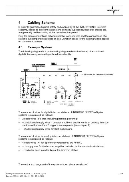
4.1 Example System<br />
The following diagram is a typical wiring diagram (branch scheme) of a combined<br />
digital intercom system with public address facility:<br />
1DES03<br />
1MH14<br />
1DES02 +<br />
2*16DET01<br />
12DT00x 6DA00x AXA311 6DX00x CWB-ATEX 4*<br />
DSP25EExmN<br />
6DWS01 +2*HS15EEmN +HS15EEmN<br />
+CWB-ATEX<br />
Number of necessary wires<br />
The number of wires <strong>for</strong> digital intercom stations of <strong>INTRON</strong>-D / <strong>INTRON</strong>-D plus<br />
systems is calculated as follows:<br />
• 2 basic wires (a/b lines including phantom powering)<br />
• + 2 additional supply wires if booster amplifiers, ancillary units or desktop intercom<br />
stations with more than 2 keypads are employed (see chapter 7)<br />
• + 2 additional supply wires <strong>for</strong> flashing beacons<br />
The number of wires <strong>for</strong> analog intercom stations of <strong>INTRON</strong>-D / <strong>INTRON</strong>-D plus<br />
systems is calculated as follows:<br />
• 4 basic wires (+/- <strong>for</strong> Spannungsversorgung, a/b für NF),<br />
• + 1 supply wire <strong>for</strong> the booster amplifier (included in the standard calculation)<br />
• + 1 wire <strong>for</strong> each installed key at the intercom station<br />
The central exchange unit of the system shown above consists of:<br />
<strong>Cabling</strong> <strong>Guidelines</strong> <strong>for</strong> <strong>INTRON</strong>-D / <strong>INTRON</strong>-D plus 4 / 24<br />
Doc. no. 330-001-403 • Rev. 9 • EN • 15.10.2010