BRS-6 General Installation Guide - CAFE Foundation
BRS-6 General Installation Guide - CAFE Foundation
BRS-6 General Installation Guide - CAFE Foundation

You also want an ePaper? Increase the reach of your titles
YUMPU automatically turns print PDFs into web optimized ePapers that Google loves.
D<br />
C<br />
B<br />
A<br />
6 5<br />
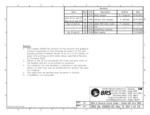
Notes:<br />
1. Part number 020001-03 consists of the textural and graphical<br />
contents presented on the following 48 sheets of this part<br />
drawing printed in booklet format on 8-1/2 x 5-1/2 sheets of<br />
paper with printing on both sides unless specified otherwise<br />
on Purchase Order.<br />
2. Sheets 2 and 50 are considered the front and back cover of<br />
the booklet and are to be printed on cardstock.<br />
3. The titleblock for this document is omitted on the following<br />
sheets so that they may be printed directly without the need<br />
for cropping.<br />
4. This page must be omitted when document is printed.<br />
5. Traceability: Lot Controlled<br />
ENG TK<br />
MFG<br />
KM<br />
6 5<br />
4<br />
3<br />
2<br />
Titleblock/Form No. 500, Issued 3/21/2002<br />
The information contained in this drawing is the sole property of <strong>BRS</strong> Inc. Any reproduction in part or whole without the written permission of <strong>BRS</strong> Inc. is prohibited.<br />
4 3<br />
2<br />
1<br />
Zone Rev' ECO<br />
Revisions<br />
Description Drafter Date<br />
- 1A 1218 initial release B. Torgerson 9/16/2007<br />
shts 12-14, and 45<br />
(pgs 10-12, and 43)<br />
2B 1386 redrawn with changes F. Hoffman 6/27/2007<br />
Pgs 43 and 44 3A 1416 added 1050 DAeC model P. Jacobson 11/1/2007<br />
- 3B n/a n/a - -<br />
- 3C 1419 consistency revisions - 11/19/2007<br />
Pg. 19 and 42 3D 1428 DAeC update 1/7/2008<br />
Defaults:<br />
Inches [MM]<br />
ASME Y14.5-1994<br />
2 Plc: N/A<br />
3 Plc: N/A<br />
Angles: N/A°<br />
<strong>BRS</strong>-6 <strong>General</strong> Install <strong>Guide</strong> - Model 600 thru 1800<br />
<strong>BRS</strong> No. 020001-03,<br />
Rev. D, Sht 1 of 49<br />
1<br />
D<br />
C<br />
B<br />
A
BALLISTIC RECOVERY SYSTEMS, INC.<br />
GENERAL INSTALLATION GUIDE<br />
FOR<br />
<strong>BRS</strong>-6 EMERGENCY PARACHUTE RECOVERY SYSTEMS<br />
(Models: 600, 800, 1050, 1350, 1350HS, 1600, & 1800)<br />
<strong>BRS</strong> Part № 020001-03, Revision D<br />
Copyright © 2008 Ballistic Recovery Systems, Inc.
This guide complies with applicable sections of ASTM F 2316,<br />
“Standard Specification for Airframe Emergency Parachutes<br />
for Light Sport Aircraft”<br />
This guide supersedes and replaces all previous<br />
<strong>BRS</strong> <strong>Installation</strong> <strong>Guide</strong>s<br />
Use of the <strong>BRS</strong> (ballistic recovery system) unit is for emergency<br />
situations only. Such use may subject you to mishap, injury, and<br />
even death. Since <strong>BRS</strong> cannot govern use of the unit, <strong>BRS</strong> hereby<br />
disclaims all liability.<br />
Modification of any component part of the <strong>BRS</strong> unit, or failure to<br />
strictly follow the procedures and directions set forth in this<br />
guide or supplemental material provided by <strong>BRS</strong>, can result in<br />
deployment failure and personal injury or death to the pilot and<br />
any passengers aboard the aircraft.<br />
Proprietary Notice<br />
The information contained in or disclosed by this document is<br />
considered proprietary to Ballistic Recovery Systems, Inc. This<br />
document and the items and information contained or disclosed<br />
within shall not be used, copied, or reproduced in whole or in part,<br />
nor shall the contents be revealed in any manner to any person<br />
unless written permission is obtained from Ballistic Recovery<br />
Systems, Inc.
THIS PAGE LEFT INTENTIONALLY BLANK<br />
<strong>BRS</strong>-6 <strong>General</strong> <strong>Installation</strong> <strong>Guide</strong> (Models 600 through 1800) Page 2 of 47<br />
<strong>BRS</strong> Document № 020001-03 Revision D Copyright © 2008, <strong>BRS</strong> Inc.
Introduction<br />
TABLE OF CONTENTS<br />
<strong>BRS</strong> SYSTEM BASICS ...........................................................................................7<br />
1. The Parachute .......................................................................................7<br />
2. The Slider.............................................................................................9<br />
3. The Rocket Assembly............................................................................. 10<br />
4. The Activation Assembly ........................................................................ 13<br />
5. The Bridles and Harnesses ...................................................................... 15<br />
<strong>Installation</strong> <strong>Guide</strong><br />
PROPER SYSTEM SELECTION............................................................................... 18<br />
1. Size of System ..................................................................................... 18<br />
2. Style of System .................................................................................... 18<br />
A. Canister (Sleeve Deployed) .................................................................. 18<br />
B. Softpack (Sleeve Deployed) .................................................................. 19<br />
C. Softpack (Bag Deployed)...................................................................... 20<br />
D. VLS (Vert. Launch System, Sleeve Deployed)............................................ 20<br />
SYSTEM MOUNTING.......................................................................................... 21<br />
1. Normal Operations................................................................................ 21<br />
2. Pilot and Passenger Safety ..................................................................... 21<br />
3. Weight and Balance .............................................................................. 22<br />
4. Structural ........................................................................................... 22<br />
5. Direction of Fire................................................................................... 23<br />
6. Egress................................................................................................ 25<br />
7. Service and Inspection Access.................................................................. 26<br />
PARACHUTE ATTACHMENT ................................................................................ 27<br />
1. Ultimate Loads, Rated Loads, and Safety Factors ........................................ 27<br />
2. Aircraft Structure Analysis ..................................................................... 28<br />
3. Harness Design Analysis ......................................................................... 29<br />
A. Aircraft Dynamics at Deployment .......................................................... 30<br />
B. Aircraft Descent and Touchdown Attitude................................................ 34<br />
C. Propeller or Empennage Entanglement ................................................... 35<br />
4. Harness Routing ................................................................................... 36<br />
5. Harness Styles ..................................................................................... 38<br />
ACTIVATION HANDLE MOUNTING ......................................................................... 39<br />
ACTIVATION HANDLE ROUTING ........................................................................... 40<br />
FINAL NOTES ................................................................................................. 41<br />
<strong>BRS</strong>-6 System Parameters<br />
Customer Loads Determination Worksheet<br />
<strong>BRS</strong>-6 <strong>General</strong> <strong>Installation</strong> <strong>Guide</strong> (Models 600 through 1800) Page 3 of 47<br />
<strong>BRS</strong> Document № 020001-03 Revision D Copyright © 2008, <strong>BRS</strong> Inc.
THIS PAGE LEFT INTENTIONALLY BLANK<br />
<strong>BRS</strong>-6 <strong>General</strong> <strong>Installation</strong> <strong>Guide</strong> (Models 600 through 1800) Page 4 of 47<br />
<strong>BRS</strong> Document № 020001-03 Revision D Copyright © 2008, <strong>BRS</strong> Inc.
INTRODUCTION<br />
Thank you for considering the new <strong>BRS</strong>-6 Emergency Parachute System, the highest<br />
quality, most innovative product of its kind. With worldwide sales exceeding 20,000 units and<br />
over 206 saved lives to its credit, <strong>BRS</strong> has the most successful and popular systems available.<br />
<strong>BRS</strong> Emergency Parachute Systems utilize a manually activated, solid propellant rocket motor<br />
to extract a round, non-steerable parachute and recover the aircraft in life-threatening<br />
emergency situations. With adequate altitude, it is designed to lower it to the ground at a<br />
survivable rate of descent. Current products are the result of more than 25 years of <strong>BRS</strong><br />
experience in designing, testing, manufacturing, and servicing ballistically deployed parachutes<br />
for aircraft. Functional and structural reliability have been essential to their successful<br />
development.<br />
<strong>BRS</strong> has sold units for over 300 different types of ultralight aircraft, experimental aircraft, and<br />
military unmanned aerospace vehicles (UAVs). In addition, there are FAA-certified systems<br />
currently installed on every Cirrus Design SR20 and SR22 aircraft, and select Cessna models<br />
(C150, C172, and C182) as an aftermarket STC product. The use of proven parachute and<br />
rocket motor technology has been a key factor in this endeavor. The materials, components,<br />
design methods, and production methods used in the <strong>BRS</strong> solid propellant rocket motors,<br />
parachutes, and related components have been adapted from military applications that have<br />
evolved through hundreds of projects over the past several decades. <strong>BRS</strong> maintains that our<br />
units have been tested under more conditions, in a greater selection of aircraft, and through a<br />
broader variety of potential use modes than any other emergency backup parachute system<br />
intended to recover aircraft and occupants together.<br />
While the <strong>BRS</strong> Emergency Parachute System will not make your flying absolutely safe, it will<br />
provide you with additional safety, if used according to this guide and with common sense.<br />
<strong>BRS</strong> Incorporated is a publicly held company based in South St. Paul, Minnesota. A full-time<br />
staff is available to assist you with any needs you may have relative to your purchase of a <strong>BRS</strong><br />
unit. If you have questions of any type, feel free to contact the company using the following<br />
information:<br />
Ballistic Recovery Systems, Incorporated<br />
300 Airport Rd<br />
South Saint Paul MN 55075-3551 • USA<br />
Telephone: (651) 457-7491<br />
(763) 226-6110 (Emergency Only)<br />
FAX: (651) 457-8651<br />
Email: info@<strong>BRS</strong>parachutes.com<br />
Website: www.<strong>BRS</strong>parachutes.com<br />
Hours: Mon-Fri, 8:00 AM to 5:00 PM CT<br />
<strong>BRS</strong>-6 <strong>General</strong> <strong>Installation</strong> <strong>Guide</strong> (Models 600 through 1800) Page 5 of 47<br />
<strong>BRS</strong> Document № 020001-03 Revision D Copyright © 2008, <strong>BRS</strong> Inc.
This document contains important information for both current and potential owners, as it<br />
gives a general overview of the most critical aspects of a parachute installation to be<br />
considered when planning the integration with your aircraft. This guide should be used in<br />
conjunction with the <strong>BRS</strong>-6 Owner’s Manual to provide the most complete and accurate<br />
information about our systems.<br />
Please keep in mind that this document is not tailored to any particular aircraft and was kept<br />
generic enough to cover most applications. <strong>BRS</strong> may have additional installation instructions or<br />
guides for your particular aircraft to supplement this document. These instructions will give<br />
specific direction and use illustrations or photographs of the aircraft. However, for custom<br />
orders, it is very likely that <strong>BRS</strong> will not have any supplemental instructions, since it is costprohibitive<br />
to develop a complete set of instructions for an order of one.<br />
IMPORTANT NOTICE: All current owners MUST completely read this guide. As<br />
an owner of a <strong>BRS</strong> system, it is absolutely mandatory that you completely<br />
read this guide before installing or using your new unit. Failure to install,<br />
maintain, and/or use the <strong>BRS</strong> could result in personal injury or even death<br />
to you or your passengers, and damage to your aircraft.<br />
Before purchasing a <strong>BRS</strong> product for non-certified aircraft, each customer shall understand and<br />
accept in writing the following disclaimer:<br />
o <strong>BRS</strong> products are not designed for a specific aircraft<br />
o <strong>BRS</strong>’s representations and warranties regarding this product, including, without<br />
limitation, the performance specifications of this product shall only apply to the extent<br />
the product is used within the scope of its formal Product Specification. <strong>BRS</strong> Product<br />
Specifications may be obtained by contacting <strong>BRS</strong>.<br />
o Any reference by <strong>BRS</strong> to an aircraft model, including, without limitation, illustrations<br />
and installation guidance, is based on the informal accumulation of customer<br />
experiences that have been shared with <strong>BRS</strong> and are now being passed on to<br />
subsequent customers without any formal testing by <strong>BRS</strong>, without any agreement with<br />
the manufacturer of such aircraft model, and without ongoing scrutiny or formal<br />
consideration by <strong>BRS</strong>.<br />
o The customer shall be responsible for the appropriate installation and maintenance of<br />
this product. <strong>BRS</strong> will not, in any event, be responsible for any installation or<br />
maintenance even if the customer has discussed the specific installation with <strong>BRS</strong> and<br />
received what the customer believes to be specific instructions.<br />
o The installation of a <strong>BRS</strong> product will affect the weight and balance of the aircraft and<br />
its handling.<br />
If you have any questions or are unsure of any portion of this guide, please call or write before<br />
proceeding in error. <strong>BRS</strong> wishes for you to fully understand the proper use of the <strong>BRS</strong> system<br />
for your safety and that of your passengers.<br />
In addition to boldface type, important information will be highlighted with:<br />
<strong>BRS</strong>-6 <strong>General</strong> <strong>Installation</strong> <strong>Guide</strong> (Models 600 through 1800) Page 6 of 47<br />
<strong>BRS</strong> Document № 020001-03 Revision D Copyright © 2008, <strong>BRS</strong> Inc.
<strong>BRS</strong> SYSTEM BASICS<br />
The following discussion is useful to better understand the basics of what you are about to<br />
consider installing on your aircraft. You’ll come to depend on it and you’ll want to understand<br />
it. This information is also repeated in the <strong>BRS</strong>-6 Owner’s Manual.<br />
1. The Parachute<br />
Round, non-steerable parachutes are used for aircraft recovery because their purpose is<br />
simple, to slow an aircraft to a descent speed that is conducive to a safe touchdown. It is this<br />
simplicity that enhances their reliability.<br />
Parachutes are fabricated from woven textiles in the form of fabrics, tapes, webbing, and<br />
thread. The basic structure of a round parachute (shown in Fig. 1) consists of the canopy and<br />
suspension lines. The canopy, which creates the aerodynamic drag, is made up of a series of<br />
fabric panels or "gores" sewn together to form its desired shape. The canopy has a vent at its<br />
center to allow some air to escape in a controlled manner and thus reduce oscillations and<br />
provide a stable descent. Vent lines are attached to the perimeter of the vent and routed<br />
symmetrically across its center to provide structural support and maintain its shape.<br />
The suspension lines are attached to the "skirt" of the canopy and converge to a riser or set of<br />
risers at the opposite end. The canopy structural integrity is enhanced by a "skeleton" of tapes<br />
and webbings sewn nearly perpendicular to each other to the top surface of the canopy fabric.<br />
Radial bands run from opposite suspension line attachment points, across the top of the<br />
canopy. The skirt band, vent band, and circumferential bands run around the circumference<br />
of the canopy. The precise geometry of the canopy shape, positioning of the structural<br />
reinforcement and choice of materials are all adjusted for each particular application, striking<br />
a balance between opening characteristics, strength, stability and rate of descent.<br />
<strong>BRS</strong>-6 <strong>General</strong> <strong>Installation</strong> <strong>Guide</strong> (Models 600 through 1800) Page 7 of 47<br />
<strong>BRS</strong> Document № 020001-03 Revision D Copyright © 2008, <strong>BRS</strong> Inc.
Canopy<br />
Vent<br />
Figure 1.<br />
<strong>BRS</strong> Parachute Assembly<br />
Circumferential Bands<br />
Slider<br />
Riser<br />
Radials Bands<br />
Skirt<br />
Suspension Lines<br />
<strong>BRS</strong>-6 <strong>General</strong> <strong>Installation</strong> <strong>Guide</strong> (Models 600 through 1800) Page 8 of 47<br />
<strong>BRS</strong> Document № 020001-03 Revision D Copyright © 2008, <strong>BRS</strong> Inc.
With a few minor exceptions, all of the textile components in our parachute systems are<br />
fabricated from either Kevlar® or Nylon. The materials used in <strong>BRS</strong> parachutes, including the<br />
fabric, reinforcement tapes, suspension lines, and threads, are all woven to military or industry<br />
specifications that define specific parameters such as raw fiber materials, yarn count, yarn<br />
twist, weave type, and finish.<br />
Parachute material strength requirements are ultimately based on deployment characteristics,<br />
or specifically, deployment loads. A typical deployment load profile begins with a snatch force<br />
which occurs when the parachute assembly is initially extracted from its container and pulled<br />
to full line stretch. This is usually not felt by the pilot/passenger. When air begins to fill the<br />
canopy, higher inflation loads result. The number and magnitude of the peak loads is<br />
dependent on airspeed at deployment, payload weight, and atmospheric conditions.<br />
2. The Slider<br />
After the parachute is completely extracted and exposed to the relative wind, it begins to<br />
inflate, generating drag forces to decelerate the airplane. The magnitude of these drag forces,<br />
or inflation loads, for a particular parachute design is a function of the airplane's weight, the<br />
airspeed at deployment, and the rate of inflation.<br />
The inflation rate of <strong>BRS</strong> parachutes is controlled by a proprietary slider, an annular shaped<br />
fabric panel with metal grommets along its perimeter. The parachute suspension lines are<br />
routed through the grommets such that the slider is free to move along the suspension lines.<br />
The parachute is packed with the slider positioned at the top of the suspension lines. Since the<br />
diameter of the slider is significantly less than the open diameter of the canopy, it limits the<br />
initial open diameter of the parachute and its rate of inflation as shown in Fig. 2. Once the<br />
dynamic pressure acting on the system decreases to a safe level, the slider moves down the<br />
lines, allowing the parachute to inflate to its full diameter.<br />
Maximum Reefed Disreefing Full Canopy Deployment<br />
Condition Condition<br />
Figure 2.<br />
<strong>BRS</strong> Annular Slider<br />
Sliders can be "tuned" for a particular set of deployment conditions by adjusting their<br />
geometry. For example, increasing the size of the slider's vent will increase the airflow into the<br />
parachute and therefore increase the initial rate of inflation. Decreasing the fabric area will<br />
decrease the drag on the slider and allow it to disreef at a higher dynamic pressure, thereby<br />
increasing the final rate of inflation.<br />
<strong>BRS</strong>-6 <strong>General</strong> <strong>Installation</strong> <strong>Guide</strong> (Models 600 through 1800) Page 9 of 47<br />
<strong>BRS</strong> Document № 020001-03 Revision D Copyright © 2008, <strong>BRS</strong> Inc.
3. The Rocket Assembly<br />
All current <strong>BRS</strong> rocket motors use stored chemical energy in the form of a solid propellant to<br />
provide the thrust forces necessary to rapidly remove any enclosure cover and extract the<br />
parachute from its container. These rocket motors use a composite propellant, a<br />
heterogeneous mixture of ammonium perchlorate (AP) and aluminum powder (Al), the oxidizer<br />
and fuel. These are the most commonly used types of ingredients in modern solid propellants.<br />
A synthetic rubber binder is also necessary to provide a structural matrix to hold these<br />
ingredients together. Other typical propellant additives include burn rate modifiers to<br />
accelerate or decelerate combustion, curing agents to solidify the propellant at different rates,<br />
plasticizers to improve the processing properties, bonding agents to improve the chemical<br />
properties, and antioxidants to reduce chemical deterioration. The size, shape, and size<br />
distribution of the propellant's solid particles are also key factors in its burning characteristics.<br />
Two versions of our larger rocket assemblies, the <strong>BRS</strong>600 and <strong>BRS</strong>900, illustrated in Fig. 3,<br />
consist of the igniter, rocket motor base, and rocket motor. The rocket motor components<br />
consist of the motor case, aft bulkhead, propellant, and nozzle. The motor case/aft bulkhead<br />
contains the propellant and serves as a pressure chamber when the propellant is burning. The<br />
composite propellant is cast into grains, or solid shaped masses that fit snugly inside the motor<br />
case. To provide consistent dimensional tolerances, the grains are cast inside a filament wound<br />
internal liner that also acts as an insulator to limit heat transfer to the motor case.<br />
Our smaller rocket motors, the <strong>BRS</strong>-300, <strong>BRS</strong>-301, <strong>BRS</strong>-440 and <strong>BRS</strong>-460, do not utilize a rocket<br />
motor base, but instead attach directly to the igniter. They consist of a motor case,<br />
propellant, nozzle, and both an aft bulkhead and forward bulkhead, illustrated in Fig. 4.<br />
<strong>BRS</strong>-6 <strong>General</strong> <strong>Installation</strong> <strong>Guide</strong> (Models 600 through 1800) Page 10 of 47<br />
<strong>BRS</strong> Document № 020001-03 Revision D Copyright © 2008, <strong>BRS</strong> Inc.
Motor<br />
Case<br />
Forward<br />
Bulkhead<br />
Motor Case<br />
Launch Tube<br />
Rocket<br />
Propellant Grains<br />
Nozzle<br />
Igniter<br />
Figure 3: <strong>BRS</strong>-600/900 Rocket Diagram<br />
Rocket Motor<br />
Two Propellant Grains<br />
(3 Propellant Grains for<br />
<strong>BRS</strong>-440 and <strong>BRS</strong>-460)<br />
Nozzle<br />
Aft Bulkhead<br />
Aft Bulkhead<br />
Figure 4: <strong>BRS</strong>-300/301/440/460 Rocket Diagram<br />
Rocket Motor Base<br />
Igniter<br />
<strong>BRS</strong>-6 <strong>General</strong> <strong>Installation</strong> <strong>Guide</strong> (Models 600 through 1800) Page 11 of 47<br />
<strong>BRS</strong> Document № 020001-03 Revision D Copyright © 2008, <strong>BRS</strong> Inc.
The igniter, illustrated in a cut-away view in Fig. 5, is a mechanical device which requires no<br />
electrical source. The igniter consists of a firing pin actuator, a steel spring, a plunger to<br />
which the activation cable is attached, and two firing trains. Each firing train consists of a<br />
firing pin and primer which ignites a primary booster at the end of the igniter. In its normal<br />
position the firing pin actuator and plunger are interlocked with two small ball bearings held in<br />
place by the inner wall of the igniter body.<br />
Pulling the activation cable compresses the spring and cocks the plunger. One half inch of<br />
plunger travel is required to release the ball bearings and allow the plunger to strike the firing<br />
pins with the stored energy of the compressed spring. The firing pins then strike the shot-gun<br />
primers which ignites a black powder and magnesium primary booster in the end of the igniter.<br />
The igniter is unarmed in its normal configuration since the spring is uncompressed and the<br />
plunger is separated from the firing pins by a 0.060-inch gap.<br />
In the <strong>BRS</strong>-600 and <strong>BRS</strong>-900, the igniter primary booster ignites a secondary black powder and<br />
magnesium booster contained in the rocket motor base. The extra booster material is used to<br />
insure ignition of the larger rocket motor. The rocket motor base has a conical protrusion<br />
which sprays hot particles past the rocket nozzle and across the surface of the rocket motor's<br />
solid propellant grains. This extra booster is not present in the smaller <strong>BRS</strong>-300/301/440/460<br />
rockets.<br />
Firing Pins (2)<br />
Primers (2)<br />
Primary<br />
Boosters<br />
Firing Pin Actuator<br />
Plunger<br />
Spring<br />
Normal Position<br />
Armed Position<br />
(Spring in compression)<br />
Firing<br />
Ball Bearings<br />
Igniter Body<br />
Figure 5: Igniter Activation Diagram<br />
Activation Cable<br />
<strong>BRS</strong>-6 <strong>General</strong> <strong>Installation</strong> <strong>Guide</strong> (Models 600 through 1800) Page 12 of 47<br />
<strong>BRS</strong> Document № 020001-03 Revision D Copyright © 2008, <strong>BRS</strong> Inc.
Once ignited, the grains will burn on all exposed surfaces to form hot gases that are exhausted<br />
through the nozzle. The propellant's performance is a function of its burning rate and the<br />
burning surface area of the grain. The geometry of the grain is therefore critical to achieving<br />
the desired thrust profile. Our rocket motors use grains with a cylindrical bores through their<br />
centers, or internal burning grains, to achieve the desired burn surface area.<br />
The rocket motor nozzle provides for the expansion and supersonic acceleration of the hot<br />
gases. The rocket motor's performance is a function of the propellant performance and the<br />
nozzle design and can be defined by its thrust versus time curve and the total impulse, It ,<br />
which is the thrust force, F (which can vary with time) integrated over the burning time, t.<br />
Each <strong>BRS</strong> rocket motor has been designed with a thrust-time curve and total impulse that<br />
specifically meet the extraction requirements of the particular parachute.<br />
Solid fuel motors have a flame, but this is not the problem some imagine for two reasons; one<br />
simple, one more complex. With an extremely high departure velocity in the first tenth of a<br />
second, the flame is gone before it can cause problems. The more complex explanation<br />
involves a pressure front set up by the ignited fuel. The main content of the rocket’s exhaust is<br />
water vapor and non-flammable gases. These expand so rapidly that they will literally push<br />
away fuel fumes before they can get warm enough to ignite.<br />
<strong>BRS</strong> currently certifies its solid-fuel rockets for twelve (12) years of service life. At the time of<br />
expiration, the old rocket must be properly disposed of and replaced with a new one. However,<br />
this means that a rocket shipped from <strong>BRS</strong> to a customer need never be returned to the factory<br />
for service, eliminating any owner difficulty in shipping hazardous goods.<br />
4. The Activation Assembly<br />
The rocket motor is activated by pulling a red activation handle mounted securely within reach<br />
of the pilot/passenger. This handle is connected to the rocket motor igniter with a flexible,<br />
stainless steel aircraft grade cable routed through a Teflon-lined housing. The handle is usually<br />
the only part of the system accessible to the pilot in flight.<br />
Figure 6: <strong>BRS</strong> Activation Handle/Holder<br />
Two separate and deliberate pilot actions are required to deploy <strong>BRS</strong> parachutes. The first<br />
action requires that the pilot remove the safety pin from the activation handle holder during<br />
the pre-flight inspection. The second action requires the pilot to pull the activation handle<br />
several inches out of the holder. The first few inches of motion take up cable slack that has<br />
been intentionally built into the system to prevent inadvertent activation due to flexing of the<br />
<strong>BRS</strong>-6 <strong>General</strong> <strong>Installation</strong> <strong>Guide</strong> (Models 600 through 1800) Page 13 of 47<br />
<strong>BRS</strong> Document № 020001-03 Revision D Copyright © 2008, <strong>BRS</strong> Inc.
system or bumping the handle. The remaining motion (approximately ½”) activates the rocket<br />
motor. Typical pull force requirements range from 30 to 70 lbs., depending upon friction<br />
variations in the routing, temperature, and overall length of cable/housing.<br />
The mechanical activation can be best compared to a firing pin on a gun. While the analogy is<br />
not exact, the sequence is similar in that a cocking action occurs, followed by detonation of<br />
the primer (by propelling a hammer into dual igniters). In turn, the primers ignite the solid<br />
fuel. To the user, the two actions are transparent… one pull seems to do everything.<br />
Nonetheless the system indeed first cocks itself, and then releases the hammer to contact the<br />
dual primers.<br />
Proper installation of the activating housing and handle is imperative<br />
to proper operation. <strong>BRS</strong> owners should never tamper with the<br />
activation housing and handle assembly. The design intent of the<br />
assembly must be maintained for it to work properly. Any<br />
misassembled components could lead to serious injury or death.<br />
As you can see in Figure 7 and 8 below, removing the screw holding the handle twist plate onto<br />
the handle holder affects the function of the assembly. Any reassembly requires that the nylon<br />
nut threaded over the end of the plastic housing be retained behind the screw on both the<br />
handle holder (Figure 7) and cone adapter (Figure 8) that threads onto the rocket launch tube.<br />
It is extremely important that the retaining screws be long enough to stop the nut from<br />
moving, yet short enough so that they do not crush the activation housing into the cable.<br />
Figure 7: Section of Handle Holder Figure 8: Section of Cone Adapter<br />
<strong>BRS</strong>-6 <strong>General</strong> <strong>Installation</strong> <strong>Guide</strong> (Models 600 through 1800) Page 14 of 47<br />
<strong>BRS</strong> Document № 020001-03 Revision D Copyright © 2008, <strong>BRS</strong> Inc.
5. The Bridles and Harnesses<br />
Bridle is a term that <strong>BRS</strong> uses in two ways. In some cases (ultralights only), it describes a<br />
single section of webbing between the riser (previously mentioned) and an attachment point<br />
on the aircraft. In all other cases, it describes a single section of webbing attaching the riser<br />
to a set of 2-4 harnesses, which are attached directly to multiple points on the aircraft.<br />
Connections between the riser and bridle, or bridle and harnesses are typically made using a<br />
large steel “Quick Link”.<br />
Depending upon the particular system and aircraft, <strong>BRS</strong> uses Nylon or Kevlar® webbing for<br />
risers, bridles, and aircraft connection harnesses. <strong>BRS</strong> also uses stainless steel cable for bridles<br />
on certain, older aircraft designs.<br />
Nylon webbing is used:<br />
• whenever adequate elongation is necessary for absorbing opening loads.<br />
• for aircraft connection harnesses in situations where the strength and cut resistance of<br />
Kevlar® is unnecessary and a bit more stretch is preferred.<br />
Kevlar® webbing is used:<br />
• mostly for aircraft connection harnesses, as it is a high-modulus (low elasticity), low<br />
weight material with minimum breaking strength of 13,500 lbs per Parachute Industry<br />
Association (PIA) standard.<br />
• for risers in larger systems where more tensile strength is necessary and equivalent<br />
strength Nylon is prohibitively heavy.<br />
• for bridles that may come in contact with sharp metal or fiberglass (i.e. propellers).<br />
Stainless steel cables are used:<br />
• in applications where the bridle must be routed along an existing, smaller brace cable<br />
and using the webbing would add more drag.<br />
• Kevlar® or nylon does not offer enough resistance to cutting or abrasion and the<br />
additional weight/bulk is not a concern.<br />
All fabric webbing is protected against ultraviolet light damage (exposure to the sun) by fulllength<br />
nylon sheathing. After final assembly sewing, the thread is covered by opaque shrink<br />
tubing to prevent UV damage.<br />
<strong>BRS</strong>-6 <strong>General</strong> <strong>Installation</strong> <strong>Guide</strong> (Models 600 through 1800) Page 15 of 47<br />
<strong>BRS</strong> Document № 020001-03 Revision D Copyright © 2008, <strong>BRS</strong> Inc.
THIS PAGE LEFT INTENTIONALLY BLANK<br />
<strong>BRS</strong>-6 <strong>General</strong> <strong>Installation</strong> <strong>Guide</strong> (Models 600 through 1800) Page 16 of 47<br />
<strong>BRS</strong> Document № 020001-03 Revision D Copyright © 2008, <strong>BRS</strong> Inc.
INSTALLATION GUIDE<br />
<strong>BRS</strong> has helped experimental aircraft manufacturers and builders with installation and<br />
mounting guidance for over 300 different aircraft designs in the last 25 years. However, this<br />
represents only a small fraction of the aircraft designs that are currently flying or being built.<br />
It is a very daunting task for <strong>BRS</strong> to keep up to date with every single aircraft design, especially<br />
those with only a few owners or builders in the entire world. Due to the nature of<br />
experimental aircraft, almost every one of these designs has something unique for that<br />
particular aircraft.<br />
Most builders are aware that <strong>BRS</strong> has documented many of our designs with specific installation<br />
instructions. We continue to sell systems based on robust installations that have been<br />
repeated for years on aircraft kits manufactured by some of the more established companies<br />
(i.e. Quicksilver, Challenger, Kolb, Kitfox, RANS). For many of these aircraft, there may be<br />
more than one option that will work and it is up to the buyer’s discretion which to choose. For<br />
instance, one builder may want an internal softpack to save money and weight while another<br />
builder wants to save luggage space and opt to mount an external canister or VLS. In some<br />
cases, there is really only one option and it will be highly recommended that the builder use it.<br />
However, we are often approached by potential customers who wish to mount a <strong>BRS</strong> system to<br />
their aircraft, but don’t know which one is best and what is required to do it properly.<br />
This section of our manual addresses the fundamental items that <strong>BRS</strong> considers when designing<br />
or modifying an installation and will help prepare a potential <strong>BRS</strong> customer to evaluate his<br />
aircraft design for an installation that will stand the test of time and function properly if ever<br />
needed. As with the rest of this document, it is written assuming our customer is a<br />
mechanically-capable and safety-conscious builder and/or pilot.<br />
Remember, the aircraft owner is ultimately responsible for ensuring that the<br />
installation design (whether provided by <strong>BRS</strong>, the aircraft manufacturer, or the<br />
customer) is sound. If you have any concerns or questions, please call <strong>BRS</strong><br />
before completing your installation.<br />
You may view the installation of our systems as simple and straightforward. Others may not.<br />
Whatever your view, please be assured that <strong>BRS</strong> engineers do not take their jobs lightly. In<br />
many cases, they are pilots like you and realize the importance of installing a parachute system<br />
that will work when needed. Some of the many challenges <strong>BRS</strong> engineers face when helping<br />
design an installation for a particular aircraft are:<br />
• Aircraft are usually not designed for rearward and upward point loads that an inflating<br />
parachute imparts onto the airframe (up to 3-7 g’s!)<br />
• Aircraft are not necessarily designed to impact the ground with a 21-25 ft/sec. descent<br />
rate<br />
• Aircraft manufacturers frequently incorporate minor design changes and do not<br />
consider the effect upon a customer’s need for a parachute (i.e. add or remove<br />
tubing, move fuel tanks, etc)<br />
• Aircraft manufacturers increase gross weight capabilities for identical models of<br />
aircraft<br />
• Aircraft builders modify their aircraft to better suit their needs, not realizing the<br />
impact on the parachute and/or harness mounting and routing (i.e. changing engine<br />
sizes)<br />
• Aircraft are usually not locally available for <strong>BRS</strong> engineers to work with<br />
• Some aircraft have no weight and balance information available to the builder<br />
<strong>BRS</strong>-6 <strong>General</strong> <strong>Installation</strong> <strong>Guide</strong> (Models 600 through 1800) Page 17 of 47<br />
<strong>BRS</strong> Document № 020001-03 Revision D Copyright © 2008, <strong>BRS</strong> Inc.
Regardless of the obstacles, a safe, sound installation can most likely be accomplished if the<br />
<strong>BRS</strong> owner plans ahead and begins thinking about the installation before he/she purchases our<br />
life saving devices. The following are items to consider prior to a purchase, or at the least,<br />
prior to installation:<br />
PROPER SYSTEM SELECTION<br />
The appropriate <strong>BRS</strong> emergency parachute system for a given aircraft is initially based on two<br />
important specifications, dictated by the manufacturer or builder:<br />
1. Maximum GTOW (gross takeoff weight) – the weight of a fully loaded aircraft<br />
will contribute directly to the loads that the parachute canopy will experience<br />
during inflation. It also affects descent rate, since each canopy shape and<br />
overall area is sized for a particular load range to maintain a survivable rate of<br />
descent. A canopy that is too small for the aircraft weight will cause the<br />
aircraft to hit the ground faster than designed!! THIS IS AN ABOLUTE LIMIT!!<br />
2. Vne (maximum speed to never exceed) – remaining under the maximum tested<br />
deployment speed of a particular canopy is critical. The potential to increase<br />
speed beyond rated is going to exponentially increase the dynamic pressure on<br />
the canopy and reduce design safety factors. AGAIN, THE PLACARDED<br />
MAXIMUM DEPLOYMENT SPEED IS AN ABSOLUTE LIMIT!!<br />
These factors together determine the potential maximum loads that may be applied to the<br />
canopy during various phases of the deployment. Exceeding either of these conditions could<br />
seriously damage or even destroy the parachute during inflation.<br />
1. Size of System<br />
A detailed chart of the <strong>BRS</strong>-6 models currently available for sale to the ultralight, LSA,<br />
and experimental market can be found at the end of this document. Additional CAD<br />
drawings with overall dimensions are also available from <strong>BRS</strong>.<br />
2. Style of System<br />
Once it is determined which size is appropriate, the style of <strong>BRS</strong> system is your next decision.<br />
Each style has its advantages and disadvantages, depending upon: size and weight restrictions,<br />
level of weather protection necessary, likely mounting location, maintenance requirements,<br />
aesthetics, and more. <strong>BRS</strong> systems are typically purchased in one of (4) styles:<br />
Models 600, 800, and 1050<br />
A. Canister (Sleeve Deployed)<br />
The parachute canopy, suspension lines, and riser are first<br />
folded and inserted into a nylon sleeve. This sleeved assembly<br />
is then S-folded (or “sausaged”) into a plastic liner and packed<br />
with hydraulic assistance into a steel jig. A set of nylon straps<br />
and closing pin secure the compressed shape and allows the<br />
‘chute to be transferred and inserted into a cylindrical<br />
aluminum tube, closed at one end. The design uses the straps<br />
to keep the parachute compressed over time and a frangible<br />
ABS plastic cap is sealed onto the open end.<br />
<strong>BRS</strong>-6 <strong>General</strong> <strong>Installation</strong> <strong>Guide</strong> (Models 600 through 1800) Page 18 of 47<br />
<strong>BRS</strong> Document № 020001-03 Revision D Copyright © 2008, <strong>BRS</strong> Inc.
Models 600, 800, and 1050<br />
Model 1350 Only<br />
Since it is a sealed container, it can withstand exposure to the<br />
elements and needs only be inspected and repacked every 6<br />
years. It is very popular for open frame ultralights and trikes.<br />
The shape of the canisters (7” or 8” diameter x 18-22” long)<br />
lends itself to fitting into tight areas and results in a fairly<br />
small frontal profile with allows for smaller egress areas. It is<br />
heavier than an equivalent softpack. Models currently<br />
available in this style: 600, 800, and 1050.<br />
B. Softpack (Sleeve Deployed)<br />
The parachute canopy, suspension lines, and riser are first<br />
folded and inserted into a nylon sleeve. This sleeved assembly<br />
is then S-folded and packed into a durable, shaped, fabric bag<br />
by hand or hydraulic pressure. The packs are typically<br />
rectangular in shape, but variations are available at extra cost.<br />
The use of the fabric bag vs. the heavier aluminum canister<br />
results in an advantageous weight savings of 2-3 lbs. The<br />
downside to using the fabric containers, however, is that they<br />
are not sealed and can be susceptible to moisture, mold,<br />
insect, and/or rodent damage. For installations where the<br />
pack is external, the chute will require yearly inspections and<br />
repacks. Other installations may allow anywhere from two<br />
year to six year service intervals, depending upon the mounting<br />
location and its level of protection from the elements.<br />
The smaller models (600, 800, and 1050 (shown above)) are<br />
supplied in a nylon bag attached to an aluminum “L” frame<br />
with nylon straps. The frame can be attached to one of many<br />
mounting plates available from <strong>BRS</strong> or to an existing bulkhead<br />
or other flat surface. The frame also acts as a mount for the<br />
ballistic rocket.<br />
The smaller bags also have the ability to be removed from the<br />
frame if desired and mounted directly to the aircraft structure<br />
with these same straps or a set of flaps with (4) evenly spaced<br />
grommet holes on either side. Because there is no “L” frame,<br />
the rocket must be mounted separately to a sufficiently strong<br />
member near the bag mounting location.<br />
The larger 1350 model (shown at left) is supplied in a nylon bag<br />
attached to an aluminum “U” frame with nylon straps.<br />
Because of its weight, there are no provisions for flaps with<br />
grommet holes. The rocket is attached directly to the frame<br />
and it is recommended that it not be mounted separately.<br />
<strong>BRS</strong>-6 <strong>General</strong> <strong>Installation</strong> <strong>Guide</strong> (Models 600 through 1800) Page 19 of 47<br />
<strong>BRS</strong> Document № 020001-03 Revision D Copyright © 2008, <strong>BRS</strong> Inc.
Model 1600/1800 shown<br />
(Model 1350HS slightly<br />
different)<br />
Models 600, 800, 1050, & 1350<br />
C. Softpack (Bag Deployed)<br />
For larger chutes, <strong>BRS</strong> prefers to use fabric bags rather than<br />
the nylon sleeves for deployment. For this design, the<br />
parachute canopy, suspension lines, and riser are S-folded and<br />
pressure packed into a rectangular steel jig. After heating to<br />
remove excess moisture and create a “set”, or form, to the jig<br />
dimensions, the ‘chute assembly is then transferred into a<br />
deployment bag and secured with locking pins. The<br />
deployment bag is surrounded by a retaining bag which is<br />
attached to an aluminum frame, via buckles or grommets. In<br />
the event of deployment, the entire deployment bag with the<br />
parachute is extracted. Again, as a fabric container, these<br />
units are not sealed from any environmental contamination and<br />
should only be installed internally, or under a protective cover.<br />
An external installation will require yearly repacks which, for<br />
this style, can be quite expensive. When installed internally,<br />
they should be inspected and repacked every 6 years. Models<br />
currently available in this style: 1350HS, 1600, and 1800.<br />
D. VLS (Vert. Launch System, Sleeve Deployed)<br />
This style is really a lightweight softpack sealed within a<br />
container. It utilizes a sleeved, S-folded canopy that is<br />
pressure packed inside a light fabric bag. This bag is then<br />
installed into a rectangular fiberglass lower shell and topped<br />
with a shaped, frangible ABS plastic cap. The overall profile is<br />
lower and it lends itself well to external applications where the<br />
chute is located directly in the airflow over the aircraft wings.<br />
It is sealed and has the same level of protection as the<br />
cylindrical canister. Unlike the other styles, the VLS can only<br />
be mounted horizontally as it is designed to fire and extract<br />
vertically. Models currently available in this style: 600, 800,<br />
1050, and 1350.<br />
NOTE: These (4) styles have been extensively tested and are readily available. Customized<br />
packaging may be used in certain situations where the aircraft manufacturer is involved and<br />
the market will bear the additional costs associated with designing, building, and testing such<br />
units. Contact the <strong>BRS</strong> factory for more information.<br />
<strong>BRS</strong>-6 <strong>General</strong> <strong>Installation</strong> <strong>Guide</strong> (Models 600 through 1800) Page 20 of 47<br />
<strong>BRS</strong> Document № 020001-03 Revision D Copyright © 2008, <strong>BRS</strong> Inc.
SYSTEM MOUNTING<br />
Mounting your <strong>BRS</strong> parachute and rocket may at first seem like a simple task. However, it is<br />
one of the most important tasks, and each <strong>BRS</strong> owner should consider the following:<br />
1. Normal Operations<br />
The first, most obvious thing to consider is the effect on normal operations<br />
required to fly safely. The unit should not be mounted where attachment<br />
brackets and or ultimate harness routing could lead to interference with<br />
control surfaces, cables, or hardware. You should not compromise the<br />
structural integrity of the aircraft by drilling or cutting unnecessary or poorly<br />
located holes and slots into tubing, sheet aluminum, or fiberglass. <strong>BRS</strong> has<br />
many sizes of mounting clamps and bands that require no drilling for square<br />
and round tubes. There are also stainless steel mounting plates that can be<br />
attached to these and positioned or rotated at various angles to clear<br />
obstacles. In the case of a pre-stressed aircraft skin (aluminum or composite),<br />
the installer should contact the aircraft designer/manufacturer to determine if<br />
removal of material will compromise the design, either structurally or<br />
aerodynamically. Adding a large parachute canister in the wrong location on<br />
top of an airfoil can create enough turbulence to cause excessive vibration or<br />
buffeting of control surfaces in the tail. Locating the system in front of cooling<br />
radiators or air cooled engines can cause engine temperatures to be higher<br />
than normal. There have even been instances where stall characteristics were<br />
affected by the presence of the parachute container in the airflow. If you have<br />
concerns over excessive drag caused by the parachute, move it inside the<br />
aircraft.<br />
2. Pilot and Passenger Safety<br />
Along with the aircraft, it is equally important that the safety of the pilot and<br />
passenger is considered. It is recommended that the intended location of the<br />
parachute and attached rocket not be so closely mounted to the pilot or<br />
passenger(s) that it could be a burn hazard if the rocket were fired. Even<br />
though the rocket has a very fast exit, it still has the ability to scorch any body<br />
part that comes in contact with the rocket flame. For anything mounted closer<br />
than 16” from the pilot or passenger(s), an additional “blast” shield of Lexan®,<br />
aluminum, fiberglass, or even wood should be considered to protect from the<br />
rocket plume as it departs.<br />
The mount should not require that harnesses be routed as to endanger the<br />
occupants head and limbs. It is a good idea to keep all attachments and<br />
routing outside of the fuselage “cage” or inner structure if possible. Another<br />
thing to remember is not to place your unit in a location where the direction of<br />
fire could be blocked by an arm or leg that is flailing about in a chaotic,<br />
emergency situation.<br />
<strong>BRS</strong>-6 <strong>General</strong> <strong>Installation</strong> <strong>Guide</strong> (Models 600 through 1800) Page 21 of 47<br />
<strong>BRS</strong> Document № 020001-03 Revision D Copyright © 2008, <strong>BRS</strong> Inc.
3. Weight and Balance<br />
As a rule, the <strong>BRS</strong> system is most commonly placed near the root tube, keel<br />
tube, or axle members of an open-cockpit ultralight, or in the fuselage of<br />
partially or fully enclosed aircraft. It should be located so as to not adversely<br />
affect aircraft weight and balance with regards to the center of gravity (CG).<br />
You may even find that the parachute system itself, positioned in a key<br />
location, may be useful in correcting an otherwise unbalanced aircraft.<br />
It is the responsibility of the pilot to ensure that the airplane is<br />
loaded properly. Operation outside of prescribed weight and balance<br />
limitations could result in an accident and serious or fatal injury.<br />
4. Structural<br />
The attachment method and structure should be adequate to bear the weight<br />
of the parachute/rocket unit while flying, but also while taxiing on bumpy turf<br />
runways or in the event of hard or emergency landings. 14 CFR Part 23, which<br />
spells out design requirements for certified aircraft, requires that items<br />
attached inside the cabin, or occupied area, of an aircraft be able to remain<br />
secure during a downward load of up to 6g, forward load of 9g, sideward load<br />
of 1.5g, and upward load of 3g during emergency landings. The force of the<br />
rocket recoil must also be considered, but will typically be of smaller<br />
magnitude than what is required to secure the parachute. Attachment of the<br />
canister, softpack, or VLS mounts to structural aluminum plate or steel tubing<br />
is common. Avoid drilling into small tubes and use clamps whenever possible.<br />
Aluminum sheet, wood, or composite materials have different load carrying<br />
capabilities depending upon thickness or bend characteristics. Individual<br />
aircraft installation design diagrams may give specific guidance if <strong>BRS</strong> has this<br />
information to offer. Some aircraft will require structural enhancement to bear<br />
the weight.<br />
Sample Canister <strong>Installation</strong> Sample Softpack <strong>Installation</strong><br />
<strong>BRS</strong>-6 <strong>General</strong> <strong>Installation</strong> <strong>Guide</strong> (Models 600 through 1800) Page 22 of 47<br />
<strong>BRS</strong> Document № 020001-03 Revision D Copyright © 2008, <strong>BRS</strong> Inc.
If you are unsure of the strength requirements for your particular<br />
system, do not proceed without first contacting <strong>BRS</strong> for further<br />
advice.<br />
5. Direction of Fire<br />
The rocket and parachute must have a clear path to exit the aircraft. The<br />
egress path must be clear of structure, tubing, control linkages, cables, and<br />
wiring. The only thing that can be in its path is a predictably frangible or<br />
easily torn material. The rocket is generally intended to fire to the rear,<br />
slightly downward, and slightly to the side (to avoid hitting any tail structure).<br />
It is very important to avoid propeller entanglement… meaning that the<br />
whole prop arc must be considered. (It is assumed that though pilots should kill<br />
the engine before deployment, this may not always be achieved by a distressed<br />
pilot.)<br />
Ideally, the rocket and parachute should have a cone-shaped safety zone that,<br />
at about a 10’ distance, would be 5’ wide. The rocket path is not entirely<br />
arrow-straight when it first exits the aircraft, as there are factors that can<br />
affect its travel. The rocket may deviate slightly when it hits the end of the<br />
cable lanyards attaching it to the parachute, due to the mass being off-center<br />
to the initial rocket path. Also, the slipstream and relative wind will be hitting<br />
the parachute canopy as it exits the aircraft and this can affect rocket<br />
trajectory. Do not allow for a corridor that is too small for parachute egress.<br />
Not only must the existing configuration of the aircraft be considered when you<br />
aim the system, but any potential changes due to a catastrophic failure must<br />
be taken into account. <strong>BRS</strong> units mounted on top of the aircraft, and intended<br />
to deploy above it, would be compromised by a failure of one or both wings in<br />
a positive mode. Therefore, the preferred direction of fire should be<br />
downward and to the rear.<br />
IMPORTANT NOTE FOR OWNERS OF FLOAT-EQUIPPED AIRCRAFT:<br />
Float-equipped aircraft (or “flying boats”) can present a dilemma when<br />
considering the optimum mounting location. If the <strong>BRS</strong> unit is placed very low<br />
on the craft, firing down and to the rear, the <strong>BRS</strong> may constantly get wet. Even<br />
though the <strong>BRS</strong>-5 is virtually waterproof, constant exposure to water should<br />
be avoided.<br />
Also, the presence of floats may hinder a clean extraction and the required<br />
routing of harnesses could be more difficult. It may be that the only<br />
acceptable location is near the top of the aircraft, firing up.<br />
The parachute does not care which direction from the aircraft it is fired…it<br />
will always inflate downwind (see Figures 9 and 10)! This is good as you can<br />
never predict which side will be up when the need for the parachute arises<br />
anyway. Please be assured that the parachute will always be above you and<br />
you will hit the ground first.<br />
<strong>BRS</strong>-6 <strong>General</strong> <strong>Installation</strong> <strong>Guide</strong> (Models 600 through 1800) Page 23 of 47<br />
<strong>BRS</strong> Document № 020001-03 Revision D Copyright © 2008, <strong>BRS</strong> Inc.
Figure 9: Deployment Sequence for Top Mounted Units<br />
Figure 10: Deployment Sequence for Bottom Mounted Units<br />
<strong>BRS</strong>-6 <strong>General</strong> <strong>Installation</strong> <strong>Guide</strong> (Models 600 through 1800) Page 24 of 47<br />
<strong>BRS</strong> Document № 020001-03 Revision D Copyright © 2008, <strong>BRS</strong> Inc.
6. Egress<br />
<strong>BRS</strong> rockets have incredible penetrating ability, but still need to tow the<br />
parachute out of the aircraft as well. Using up a significant portion of the<br />
rocket’s total thrust energy to get out of the aircraft will hinder its ability to<br />
completely remove the deployment sleeve or bag as designed. The parachute<br />
can also become hung-up or damaged passing through an opening that is<br />
partially blocked or too small. Therefore, it is imperative that careful<br />
consideration be given to creating a large enough port of exit or weakened<br />
panel for the specific unit being installed. All possible resistance or<br />
interference with the rocket’s flight path should be avoided.<br />
<strong>BRS</strong> has tested the rocket’s penetrating ability through two layers of<br />
unmodified 1.7 oz./sq. yd. aircraft fabric (Ceconite, Stits, Poly-Fiber). <strong>BRS</strong> has<br />
also experienced actual “saves” where several layers have been penetrated.<br />
However, a removable or weakened panel is highly suggested for anything<br />
heavier than 1.7 oz./sq. yd., especially pre-sewn sailcloth. This will prevent<br />
an excessive amount of the rocket’s power being used merely to penetrate the<br />
“skin.”<br />
Some acceptable ideas for proper egress through medium or heavyweight<br />
fabrics (1.7 oz./sq.yd. or more):<br />
• Completely remove a section of fabric 1” larger than the profile of the<br />
appropriate parachute and rocket. Leave open.<br />
• Completely remove a section of fabric 1” larger than the profile of the<br />
appropriate parachute and rocket. Replace with lightweight fabric.<br />
• Add small perforations in a pattern at least 1” larger than the profile of<br />
the appropriate parachute and rocket, using a “hot knife” or soldering<br />
iron. Perforations should be at most ½” apart. DO NOT USE THIS<br />
METHOD FOR MYLAR-BACKED DACRON® FABRIC.<br />
• Completely remove a section of fabric 1” larger than the profile of the<br />
appropriate parachute and rocket. Line the perimeter of the new hole<br />
with a strip of ½” Velcro® (sewn on is better). Add a new, larger piece<br />
of fabric with mating ½” Velcro® sewn on to cover the hole. Make sure<br />
that rocket will contact the new Velcro® attached cover along the<br />
edge and not in the center. The cover needs to peel back, not be<br />
pushed off.<br />
• Cut a section of fabric 2” larger than the profile of the appropriate<br />
parachute and rocket, but leave the lower side intact, creating a flap.<br />
Add a strip of ½” Velcro® to the three sides of the flap and a larger<br />
strip (1-1/2” to 2”) to the three edges of the hole.<br />
Should your aircraft have a metal or composite skin, the port of exit will have<br />
other considerations. For example, on many composite aircraft, the skin is<br />
“stressed,” that is, meant to be part of the structure. Cutting a hole without<br />
thinking may cause a serious loss of structural integrity. For such aircraft,<br />
probably only the airframe manufacturer can advise you adequately. Usually<br />
such a hole can be cut only if the adjacent area has been built up properly to<br />
carry the loads around the hole. With metal skins, the surface may or may not<br />
be structural. If yes, the same concerns apply as with composite structures.<br />
For these types of materials, it will most likely require a blow-off (blow-out)<br />
cover. Such a cover may be flush mounted if a recessed “ledge” is fabricated<br />
around the perimeter of the hole and the cover is set down in it. The cover<br />
should be made and secured in such a way that the rocket will push it out of<br />
the way, rather than punch through it. The cover may need a fairly thick<br />
<strong>BRS</strong>-6 <strong>General</strong> <strong>Installation</strong> <strong>Guide</strong> (Models 600 through 1800) Page 25 of 47<br />
<strong>BRS</strong> Document № 020001-03 Revision D Copyright © 2008, <strong>BRS</strong> Inc.
(>.100”) piece of aluminum adhered to the cover over the rocket to ensure<br />
that it cannot penetrate the fiberglass. If necessary, contact <strong>BRS</strong> for viable<br />
options and suggestions for such removable covers, doors, etc.<br />
<strong>BRS</strong> has tested rocket extraction through thin sheets (up to .063” thick) of ABS<br />
haircell plastic. ABS is brittle enough that “scoring”, or cutting part way<br />
through one side with a sharp knife, will allow it to break along a predefined<br />
pattern when impacted from the inside with the rocket body. This is the same<br />
“frangible” material used to make the inner caps for the canisters and the top<br />
cover for the VLS style. Make sure that the rocket contact point is near the<br />
edge of the panel and not in the center.<br />
<strong>BRS</strong> has performed countless parachute extraction tests through various<br />
combinations of materials and construction and has over 25 years of experience<br />
and exposure to thousands of builders. We know that the egress design on one<br />
aircraft may not necessarily apply to another. In some cases, we may have the<br />
option to do test firings through samples provided by the manufacturer or<br />
builder. Please contact <strong>BRS</strong> for advice and suggestions before cutting into your<br />
aircraft.<br />
7. Service and Inspection Access<br />
Since all systems need to be inspected and repacked at least every 6 years<br />
(sometimes every year), it will save you time and frustration if you consider<br />
mounting locations and methods that will make the parachute and rocket easy<br />
to access for inspection and/or removal. Putting an internally mounted<br />
softpack in an area completely covered with fabric will look nice, but will<br />
require cutting the fabric at least every 6 years. A visual inspection of the<br />
system every time you fly is a good idea and your installation should allow you<br />
to see what you need to.<br />
<strong>BRS</strong>-6 <strong>General</strong> <strong>Installation</strong> <strong>Guide</strong> (Models 600 through 1800) Page 26 of 47<br />
<strong>BRS</strong> Document № 020001-03 Revision D Copyright © 2008, <strong>BRS</strong> Inc.
PARACHUTE ATTACHMENT<br />
1. Ultimate Loads, Rated Loads, and Safety Factors<br />
Inflation<br />
Load<br />
<strong>BRS</strong> has tested each of the canopies referenced in this guide to meet the<br />
requirements of the new ASTM (American Society of Testing and Materials)<br />
Standard F 2316, “Standard Specification for Airframe Emergency Parachutes<br />
for Light Sport Aircraft”. Part 6.2.1 requires multiple drop tests to verify the<br />
parachute canopy strength. This standard also mandates that these drop tests<br />
be successful when performed with combinations of weight and deployment<br />
speed that will result in a design safety factor of at least 1.5. For these drop<br />
tests, on-board data acquisition equipment was used to monitor force (in Gs)<br />
imparted onto the test weight by the parachute during the deployment<br />
sequence. The maximum force measurements in both the reefed and disreefed<br />
conditions (see Figure 11) are considered the ultimate loads, since the test<br />
incorporated the design safety factor. NOTE: Ultimate load should not be<br />
confused with ultimate strength because, unlike other mechanical testing, the<br />
ultimate loads may be near, but never at the failure point.<br />
Reefed<br />
peak load<br />
Disreefed<br />
peak load<br />
<strong>BRS</strong>-6 <strong>General</strong> <strong>Installation</strong> <strong>Guide</strong> (Models 600 through 1800) Page 27 of 47<br />
<strong>BRS</strong> Document № 020001-03 Revision D Copyright © 2008, <strong>BRS</strong> Inc.<br />
Time<br />
Figure 11: Typical Inflation Load vs. Time Profile<br />
If additional drop tests are done with deployment weights and speeds at limits<br />
prescribed on <strong>BRS</strong> placards and marketing literature, the resultant forces are<br />
called rated loads. Rated loads have no safety factor added. For some<br />
canopies, <strong>BRS</strong> may not have rated load information.
Since performing even a small series of flight tests with each aircraft is usually<br />
cost prohibitive, our prescribed aircraft attachment strength minimums is<br />
normally calculated from rated or ultimate loads obtained from these deadweight<br />
drop tests. Due to drag differences of a small, dead weight (usually<br />
pallets with barrels or lead-filled steel slugs) vs. a disabled aircraft with a<br />
significant surface area, the ultimate loads from drop tests will most likely be<br />
conservative. This may lead to fairly conservative strength requirements that<br />
some home-builders or manufacturers may have trouble meeting. Additional<br />
engineering work may have to be done to distribute these loads onto more<br />
points on the aircraft or optimize harness lengths.<br />
Now, after reading the above, if you are thinking that you should use the<br />
parachute size (or manufacturer) that offers the lowest ultimate (or opening)<br />
load, please consider this:<br />
The magnitude of an ultimate load is relative to what you are trying to<br />
accomplish. You can put a larger parachute onto your aircraft and, due to a<br />
longer time required to fill and inflate the canopy, opening loads will be lower.<br />
However, a longer opening time equates to increased altitude loss before<br />
complete inflation…not something you want if you are only 100-200 ft. in the<br />
air. A lower descent rate and opening load will do you no good if you hit the<br />
ground before it inflates.<br />
In automobiles, the faster you want to stop, the harder you need to hit the<br />
brake pedal. In parachutes, the quickest opening possible, given the<br />
deployment conditions, comes from the smallest, hardest-opening canopy.<br />
However, now your aircraft will have to be built to withstand the higher loads<br />
and the higher descent rates and this is not possible in some cases.<br />
Therefore, it is a tradeoff, and <strong>BRS</strong> designs canopies to optimize a combination<br />
of opening time, load, and descent rates, not just one aspect. Aircraft builders<br />
need to choose the parachute that will most likely survive the deployment and<br />
lower them down at a safe rate of descent. They must then design their<br />
attachments as necessary.<br />
2. Aircraft Structure Analysis<br />
Aircraft are designed to fly. They are designed to take their greatest loads<br />
vertically through the aircraft structure, as these are the lift loads. The<br />
requirement to resist excessive drag loads is much less. Unfortunately, that is<br />
exactly what an inflating parachute puts onto an airframe: significant drag and<br />
force in a direction most likely never designed for.<br />
During the initial deployment sequence, the force vector coming from the<br />
inflating parachute (directly inline with the parachute riser) is always with the<br />
relative wind. The initial position of the parachute riser could then very easily<br />
be nearly parallel (
When designing the harness assembly and attachment location(s), you must<br />
always keep in mind the magnitude and direction of the loads that will be<br />
applied to the aircraft during deployment. Due to the potential of high loads<br />
pulling on the airframe in the aft direction, the addition of simple, structural<br />
compression members may be necessary, especially in wooden and fiberglass<br />
aircraft. Most aircraft are also not designed for the localized point loading that<br />
parachutes induce. The more the load can be spread out into the airframe, the<br />
better. You must contact the aircraft manufacturer for input if you are<br />
concerned about your aircraft’s construction and strength.<br />
It is also critical to have the harness(es) placed so that it takes maximum<br />
advantage of the natural balance of the aircraft. Load distribution among<br />
multiple attachment points can be adjusted by changing the location of<br />
attachment points and lengths of harnesses. More on this subject is found in<br />
“Harness Design Analysis”.<br />
When an object is suspended from a cable, the object will always adjust its<br />
position until its center of gravity (CG) is in line with the suspension cable.<br />
The same holds true for an aircraft attached to a parachute. During the entire<br />
extraction and inflation sequence, the force magnitude and vector will be<br />
constantly shifting with time as the parachute inflates and the aircraft moves<br />
to keep the CG in line with the parachute riser. Since there are an infinite<br />
number of possible deployment weight and speed combinations for each<br />
emergency, it is impossible to determine exact minimum strength requirements<br />
for any given aircraft structure. In almost all cases, conservative data from<br />
ultimate load dead-weight drop tests (as discussed in the previous section) is<br />
the only method of determining how strong the structure of the aircraft must<br />
be to successfully survive a parachute opening.<br />
With this data, <strong>BRS</strong> can provide anticipated loads for your particular<br />
application using aircraft geometry and performance information supplied by<br />
the manufacturer/builder. At the end of this manual, you will find a blank<br />
“Loads Determination” form. You should complete this and send in to <strong>BRS</strong> to<br />
help you determine how strong your attachment points must be. This requires<br />
knowledge of the aircraft center of gravity envelope as well as dimensional<br />
relationships between the CG and the proposed attachment points.<br />
3. Harness Design Analysis<br />
For many ultralight aircraft, a single “keel” or “root” tube runs forward and aft<br />
along the aircraft centerline. This tubing is usually aluminum or steel alloy and<br />
can be either square or round. If the aircraft maximum gross weight and speed<br />
are low enough, a single harness (main bridle) attached at the fully loaded CG<br />
is typically sufficient to handle the opening loads and balance the aircraft for<br />
descent.<br />
<strong>BRS</strong>-6 <strong>General</strong> <strong>Installation</strong> <strong>Guide</strong> (Models 600 through 1800) Page 29 of 47<br />
<strong>BRS</strong> Document № 020001-03 Revision D Copyright © 2008, <strong>BRS</strong> Inc.
For heavier (and wooden or composite) ultralights, multiple attachment points<br />
are preferred to help distribute the loads and allow for a proper descent<br />
attitude. Two shorter harnesses attached to opposite ends of the “root” tube is<br />
common. Other recommended locations may include gear legs, longerons,<br />
firewalls, engine mounts, spar carry-thrus, and/or cabanes. The multiple<br />
harnesses should converge to a point that is usually 4-8 ft. above the aircraft<br />
and directly overhead of the CG, with the aircraft in the desired touchdown<br />
attitude. They are coupled together with a large, stainless steel quick link and<br />
joined to the parachute riser with a single, main bridle and another quick link.<br />
At least (3) or (4) separate attachment points are recommended for wooden or<br />
composite ultralights as there is commonly no single “strong” structural<br />
member. In some cases, a “basket” or “hammock” of webbing is made to sling<br />
underneath a wooden fuselage to minimize destruction at the time of<br />
deployment. For composite frames, adding structural hard points using steel or<br />
aluminum will most likely be necessary to handle the loads in the aft and<br />
upward direction. Reinforcement with additional compression and/or tension<br />
members or additional plies of fiberglass or wood may be needed.<br />
A few things to consider when designing your harness configuration:<br />
A. Aircraft Dynamics at Deployment<br />
The proper location of the multiple harness attachments can actually help<br />
reduce the loads that a parachute may apply to the airframe, and even help<br />
reduce the loads on the canopy itself. By attaching the front harness(es) to<br />
points above and forward of the aircraft CG, an inflating parachute will tend to<br />
pitch the aircraft nose up (Figures 12-14), thereby presenting the bottom of the<br />
aircraft to the relative wind (due to the CG alignment characteristic described<br />
earlier). This creates a condition similar to an accelerated stall and<br />
immediately slows the forward speed of the aircraft. A slower aircraft speed<br />
at the point of full inflation equates to lower loads on the canopy and<br />
translates to lower loads on the airframe. The rear harness(es) will act to limit<br />
the degree of the stall and also keep the tail positioned correctly for<br />
touchdown.<br />
All Kevlar® only!!<br />
Figure 12: Deployment, Reefed (with recommended attachments)<br />
<strong>BRS</strong>-6 <strong>General</strong> <strong>Installation</strong> <strong>Guide</strong> (Models 600 through 1800) Page 30 of 47<br />
<strong>BRS</strong> Document № 020001-03 Revision D Copyright © 2008, <strong>BRS</strong> Inc.
Figure 13: Inflation, Disreef (with recommended attachments)<br />
Figure 14: Descent (with recommended attachments)<br />
<strong>BRS</strong>-6 <strong>General</strong> <strong>Installation</strong> <strong>Guide</strong> (Models 600 through 1800) Page 31 of 47<br />
<strong>BRS</strong> Document № 020001-03 Revision D Copyright © 2008, <strong>BRS</strong> Inc.
The designs of high-wing aircraft are well suited for the preferred attachment<br />
method described above. Typically, a main front wing spar connection on<br />
either side of the fuselage is ideal for the front attachments, as its location is<br />
well above and forward of the aircraft CG. In many cases, the rear wing spar<br />
connection or carry-thru may be used as the rear harness attachment location.<br />
If not, there is typically sufficient structure near the tail-cabin interface.<br />
Figure 15: Attachment Locations, High-Wing Aircraft<br />
Unfortunately, the designs of low-wing aircraft are not as straightforward. The<br />
strongest part of the aircraft- the front spar and carry-thru, is usually below<br />
and may be only slightly ahead of the aircraft CG. If one were to attach to the<br />
spar in this case, the nose of the aircraft will be forced down to allow the<br />
aircraft to align its CG with the parachute riser. Nosing over will only<br />
ACCELERATE the aircraft during the initial deployment instead of decelerating<br />
as desired. If the parachute and aircraft actually survive the increased loads,<br />
you will still be faced with a nose-down touchdown attitude.<br />
Figure 16: Deployment, Reefed (w/ incorrect attachments)<br />
<strong>BRS</strong>-6 <strong>General</strong> <strong>Installation</strong> <strong>Guide</strong> (Models 600 through 1800) Page 32 of 47<br />
<strong>BRS</strong> Document № 020001-03 Revision D Copyright © 2008, <strong>BRS</strong> Inc.
Figure 17: Inflation, Disreef (w/ incorrect attachments)<br />
Figure 18: Descent (w/ incorrect attachments)<br />
<strong>BRS</strong>-6 <strong>General</strong> <strong>Installation</strong> <strong>Guide</strong> (Models 600 through 1800) Page 33 of 47<br />
<strong>BRS</strong> Document № 020001-03 Revision D Copyright © 2008, <strong>BRS</strong> Inc.
To avoid this, it is recommended that front attachments for low-wing aircraft<br />
be at or near the top of the engine firewall. This location will again allow the<br />
aircraft to pitch up upon deployment (although not as severe as a high-wing)<br />
and stall the aircraft. The rear attachment(s) should be at or near the<br />
bulkhead separating the tail of the aircraft from the main fuselage cabin.<br />
Figure 19: Attachment Locations, Low-Wing Aircraft<br />
In many cases, <strong>BRS</strong> can provide anticipated loads using geometry<br />
information supplied by the manufacturer/builder. It is then highly<br />
recommended to complete a structural analysis of the aircraft, with<br />
these loads applied. <strong>BRS</strong> is not the aircraft designer, nor builder,<br />
and can only make educated suggestions based on past experience.<br />
It is the responsibility of the <strong>BRS</strong> owner to determine if these<br />
suggestions apply to his/her aircraft.<br />
B. Aircraft Descent and Touchdown Attitude<br />
Determination of this touchdown attitude should consider the following:<br />
1. In most cases, the touchdown angle should be such that the lower spine<br />
(lumbar region) does not carry the impact load in direct compression.<br />
The greater the touchdown angle, either nose or tail first, the less the<br />
spine will have to endure. However, the initial touchdown angle may<br />
only constitute a part of the entire touchdown event, as the aircraft<br />
may rotate after initial contact and create a secondary impact at an<br />
entirely different angle.<br />
2. The gear design of the aircraft is critical in determining which end<br />
should descend first. For tricycle gear aircraft, the nose gear should<br />
contact first. At the rate of descent of most <strong>BRS</strong> parachutes, a nosefirst,<br />
initial impact will most likely collapse the nose gear as well as<br />
the supporting structure (i.e. engine mounts, firewall, etc). This will<br />
help absorb a significant amount of energy upon landing. There is little<br />
data suggesting the preferred angle of descent for tail wheel aircraft.<br />
Some testing in Germany for sailplanes showed that aircraft with a tail-<br />
<strong>BRS</strong>-6 <strong>General</strong> <strong>Installation</strong> <strong>Guide</strong> (Models 600 through 1800) Page 34 of 47<br />
<strong>BRS</strong> Document № 020001-03 Revision D Copyright © 2008, <strong>BRS</strong> Inc.
low attitude were somewhat unstable during descent, causing the tail<br />
to guide the aircraft erratically. For the purpose of stability and<br />
predictability, it is best if “tail dragger” aircraft descend under canopy<br />
in a generally level or slight nose-low condition.<br />
3. If a nose-down touchdown is desired, the aircraft should be equipped<br />
with at least a “4-point” individual restraint system for each occupant.<br />
A “3-point” restraint, similar to a car lap and shoulder belt, may be<br />
insufficient to avoid contact with glare shields, control yokes, or the<br />
instrument panel.<br />
4. A tail-down touchdown would likely require the rear harness to be<br />
longer. Increasing the length of the rear harness can be detrimental if<br />
it is too long and allows the aircraft to be flipped on its back during<br />
initial deployment.<br />
C. Propeller or Empennage Entanglement<br />
For aircraft with the engine up front (“tractor” type), propeller entanglement<br />
is not a serious concern when determining harness and bridle lengths. This is<br />
mainly because of the tendency of the parachute canopy to open behind and<br />
above the aircraft, except in cases of severe tumbling or other catastrophic<br />
conditions. For those with the engine behind the pilot (“pusher” type), the<br />
parachute behavior is a major concern and needs to be heavily considered<br />
when designing bridles for such aircraft.<br />
AGAIN, IT IS VERY IMPORTANT THAT THE ENGINE BE SHUT OFF<br />
BEFORE DEPLOYING A <strong>BRS</strong> PARACHUTE. FAILURE TO DO SO MAY<br />
RESULT IN SERIOUS INJURY OR DEATH. The Kevlar® or stainless steel<br />
cable that <strong>BRS</strong> uses for harnesses and bridles is very resilient to cutting, yet<br />
could still be severed. Unfortunately there is nothing that can be done to<br />
guarantee that this won’t happen. However, there are a couple of steps that<br />
must be taken to increase the probability that your chute (and you!) will<br />
survive.<br />
1. <strong>BRS</strong> insists that, for single attachment designs (ultralights only), there<br />
be at least a 10 foot* section of Kevlar® or stainless steel cable bridle<br />
between the aircraft attachment point(s) and the nylon riser of the<br />
parachute assembly. In the case of pusher aircraft, if the propeller is<br />
still turning, there is a very high possibility that the bridle will come<br />
into contact with it. By keeping the nylon riser far enough away from<br />
the prop after extraction, it ensures that the Kevlar®, not the nylon,<br />
will bear the prop strike. If the Kevlar® or stainless steel cable<br />
survives contact with a turning propeller, it may wrap up into the hub<br />
of the propeller and stop it, break off the propeller blade, or just<br />
glance off. In these cases, you are thankfully still attached to the<br />
parachute, although possibly descending at a nose down attitude.<br />
<strong>BRS</strong>-6 <strong>General</strong> <strong>Installation</strong> <strong>Guide</strong> (Models 600 through 1800) Page 35 of 47<br />
<strong>BRS</strong> Document № 020001-03 Revision D Copyright © 2008, <strong>BRS</strong> Inc.
2. For aircraft with multiple attachment points, the same 10 foot* rule<br />
must be used from the convergence point of the front and rear<br />
harnesses or attachments that are down to gear legs. Obviously all<br />
attachments should be on the forward side of the propeller.<br />
* Some instances may require more distance to clear the propeller.<br />
Please contact <strong>BRS</strong> for a recommended length if you are unsure.<br />
3. When you are mounting and aiming your parachute and rocket, make<br />
sure that the trajectory will carry the parachute well out of the path of<br />
the propeller. Keeping your mounting location as far away from the<br />
propeller as possible will always be safer.<br />
4. If your aircraft has a T-tail, it is also imperative that sufficient length<br />
be used for the bridle to help the nylon riser clear and avoid contact<br />
with the tail. The Kevlar® bridle will be better suited for contact with<br />
potentially sharp or jagged parts on the aircraft.<br />
5. If your aircraft has had a catastrophic structural failure or mid-air<br />
collision, the results may be such that the aircraft wings or tail section<br />
is whipping about and causing the parachute harnesses to be wrapped<br />
up within the wreckage. Using a lengthy Kevlar® bridle/harness system<br />
will help keep the nylon riser and suspension lines at a sufficiently<br />
safer distance.<br />
4. Harness Routing<br />
Once the harness attachment points and minimum lengths have been<br />
established, it is important to decide how the harnesses will be routed and<br />
protected/concealed as they travel from the attachment point to where the<br />
parachute is mounted and installed. For many open air ultralights and trikes<br />
where the attachment locations are near the parachute, the harnesses are<br />
simply S-folded and stowed, using plastic tie wraps to secure them. However,<br />
for more complex routing, the following “best practices” need to be followed:<br />
A. Because of the importance of bridle and harness routing, <strong>BRS</strong> will usually<br />
advise a specific path which is least likely to conflict with control<br />
mechanisms or entangle with the propeller and drive train. On some<br />
aircraft, especially those that were modified from the airframe<br />
manufacturer’s design, the suggested routing path may not be appropriate.<br />
If you feel the <strong>BRS</strong>-suggested routing is wrong for your aircraft, please<br />
contact <strong>BRS</strong> before installing.<br />
B. Harnesses should not be routed as to endanger the occupants head and<br />
limbs. It is a good idea to keep all attachments and routing outside of the<br />
fuselage “cage” or inner structure if possible.<br />
C. If you were sent a single steel bridle, do not coil any excess steel cable (for<br />
example, extra length is purposely provided with top-mounted <strong>BRS</strong> units).<br />
Excess cable should be “figure-S” folded to avoid tangling or knotting on<br />
rapid deployment. Most models use Kevlar® bridles and harnesses in lieu<br />
of steel cable, especially on enclosed cabin aircraft. Kevlar® should be Sfolded<br />
or laid flat for compact storage and, if possible, should be shielded<br />
to help keep it from being exposed to the sun or other elements. The<br />
bridle should fit without excessive length and without coming up short. If<br />
<strong>BRS</strong>-6 <strong>General</strong> <strong>Installation</strong> <strong>Guide</strong> (Models 600 through 1800) Page 36 of 47<br />
<strong>BRS</strong> Document № 020001-03 Revision D Copyright © 2008, <strong>BRS</strong> Inc.
you feel you have been supplied the wrong lengths of bridle or<br />
harnesses, please contact <strong>BRS</strong> before installing.<br />
D. Assure the bridle or harness routing does not interfere with the rocket<br />
firing. For example, do not route the bridle directly in front of the exit<br />
end of the parachute canister (over the plastic caps for the canister and<br />
VLS, or over the softpacks Velcro flap). The rocket may be deflected<br />
considerably if it strikes the bridle, and this may cause a malfunction of<br />
the extraction.<br />
E. Assure the airframe bridle or harnesses will not rub against abrasive metal<br />
parts or components of your airplane. Make sure this is true not only in its<br />
fixed routed position, but once it starts to transition behind and,<br />
eventually, overhead of the aircraft. <strong>BRS</strong> engineers have already<br />
considered such potential when designing the installation; following those<br />
guidelines should avoid problems. The routing should keep the harnesses<br />
and bridles from being damaged during disassembly and/or transport of the<br />
aircraft. If you feel the provided instructions won’t work on your<br />
aircraft, please contact <strong>BRS</strong> before proceeding.<br />
F. Assure the main bridle is routed to the same side of the aircraft as the<br />
rocket discharge (so the aircraft is not flipped over on canopy opening).<br />
Visualize the parachute deploying from its container. When the bridle is<br />
pulled tight by the opening forces, it should be free to straighten out<br />
without wrapping under the airframe. Routing the bridle on the same side<br />
the rocket will fire is key to the correct unleashing motion.<br />
G. After the above items are taken into consideration, plan your routing and<br />
measure the necessary lengths for each harness in its stowed configuration.<br />
Usually the longest required length will help us determine the minimum<br />
length of the front harnesses. The rear harnesses are usually sized<br />
according to desired touchdown attitude.<br />
H. When the optimal routing is determined and lengths are verified, secure<br />
the airframe bridle and harnesses with the provided nylon tie wraps so that<br />
they are very well attached. Use enough to keep the harnesses in place,<br />
but not too many that they will hinder a deployment. They should be no<br />
less than 6-8” apart, especially the ones holding the main bridle. In some<br />
situations, you may double them up, where failure of one would be an inflight<br />
safety issue. Ultraviolet light damage will seriously weaken nylon tie<br />
wraps. Assume that over a period of time, some of these ties may come<br />
loose or break off. If so, the owner must assure the bridle should still not<br />
interfere with the operation or strength of the aircraft. This suggests you<br />
should replace all nylon tie wraps at least annually if they have any<br />
exposure to sunlight.<br />
I. Again, be absolutely sure the bridle does not interfere with the prop<br />
arc. If a propeller should strike the bridle with any force, the integrity<br />
of the <strong>BRS</strong> bridle may be weakened dangerously. Though testing has not<br />
revealed any particular vulnerability, any propeller has the ability to<br />
undermine the strength of <strong>BRS</strong> bridles or severe them completely.<br />
<strong>BRS</strong>-6 <strong>General</strong> <strong>Installation</strong> <strong>Guide</strong> (Models 600 through 1800) Page 37 of 47<br />
<strong>BRS</strong> Document № 020001-03 Revision D Copyright © 2008, <strong>BRS</strong> Inc.
5. Harness Styles<br />
Regarding not the attachment location but rather the means of connection to<br />
the airframe, you have three choices for harness terminations:<br />
A. “A” End - In some cases, where there is a desire to attach to a flat<br />
structure (i.e. firewall or fuselage skin of a composite or aluminum<br />
aircraft), a metal tab is sewn into a loop at one end of the harness. This<br />
tab has a ½” dia. hole for an AN-8 bolt (or AN-6 with a bushing). Other<br />
uses include attachment to existing bolts at wing spars and gear legs, or<br />
welded tabs on tube frame aircraft. The opposite end of the harness is<br />
always a “C” end loop.<br />
B. “B” End- This style is intended to be routed around some part of the<br />
airframe (tubing, spar carry-thru, gear leg) and the short loop (“C”) end of<br />
the harness is passed back through a large loop (“B”) end. This is cinched<br />
up tight and the harder you pull on the one end, the tighter it gets. The<br />
“B” end loop is typically 8” in length and has one half-twist to keep the<br />
weave of the Kevlar® from receiving uneven load. This is the most<br />
common style.<br />
C. “C” End- This is a short loop (3” in length) designed to be used with the<br />
large stainless steel quick links that are common with <strong>BRS</strong> systems. Both<br />
ends are of this style.<br />
“A” End “B” End “C” End<br />
On some designs, specific attachment points may require custom attachment<br />
fittings that are not available from <strong>BRS</strong>. Special situations require consultation<br />
with <strong>BRS</strong> engineers and fittings may have to be sent to <strong>BRS</strong> for sewing onto the<br />
harness prior to installation.<br />
<strong>BRS</strong>-6 <strong>General</strong> <strong>Installation</strong> <strong>Guide</strong> (Models 600 through 1800) Page 38 of 47<br />
<strong>BRS</strong> Document № 020001-03 Revision D Copyright © 2008, <strong>BRS</strong> Inc.
ACTIVATION HANDLE MOUNTING<br />
As with bridle and harness routing, the placement and mounting of the activating handle is best<br />
done with some preplanning. It is paramount, of course, that the handle be in a place easily<br />
accessed by the pilot or passenger in a situation of great stress. The most obvious mount<br />
location is in some place where the pilot and/or passenger can physically see the mount. You<br />
must also assume that the aircraft may be experiencing high G-loads which may not permit you<br />
to easily raise your hand above your head or to places that are otherwise awkward.<br />
It is probably best to actually sit oneself in the cockpit, and physically consider where the<br />
optimum location is. <strong>BRS</strong> can suggest specific locations but handle placement is a rather<br />
personal decision. Assure you can reach the selected position from all seats. Place the handle<br />
in a location that can’t be easily bumped while entering or performing normal aircraft control<br />
movements. For best leverage, place the handle so that it is facing you and you will have to<br />
pull it towards you to activate it. Keep it low to allow you to reach it in a high G-load<br />
emergency situation.<br />
With the current handle design, the activating handle may be freely rotated in its holder to<br />
provide a better position for activation. This is may not be true for older models series (i.e.,<br />
<strong>BRS</strong>-4 and earlier).<br />
<strong>BRS</strong> can provide handle mount clamps for various sizes of tubing or can supply a simple standoff<br />
to mount the handle holder to a flat surface with an existing fastener. Either mount is equally<br />
desirable; again, the primary consideration is ease of access and use. If you have further<br />
questions about its installation, contact <strong>BRS</strong>.<br />
The safety pin only secures the firing handle to its mount. It does not prevent triggering if the<br />
housing is pulled forcefully. For example, if you were to remove the canister mount and pull<br />
the whole canister and rocket away from the handle, the rocket could fire because the action<br />
is the same as if the handle was pulled. Of course, you should not remove and pull the<br />
canister; this is merely an example to explain the possibility. If the housing (the plastic sheath<br />
protecting the activating cable inside) is properly secured along its path with durable<br />
attachments, the unit has little likelihood of deployment by force exerted on the housing<br />
itself.<br />
<strong>Installation</strong>s with sloppy or dangling housings are not adequately safeguarded against activation<br />
by a force pulling directly on the housing. If you have any questions on this subject please<br />
contact <strong>BRS</strong> for advice.<br />
<strong>BRS</strong>-6 <strong>General</strong> <strong>Installation</strong> <strong>Guide</strong> (Models 600 through 1800) Page 39 of 47<br />
<strong>BRS</strong> Document № 020001-03 Revision D Copyright © 2008, <strong>BRS</strong> Inc.
ACTIVATION HANDLE ROUTING<br />
Ideally, it is best to run the cable housing in a straight course from the rocket to the mounting<br />
location. However, this is usually not possible or practical on most aircraft. In these cases,<br />
you must assure that the housing routing follows these simple rules:<br />
1. The housing should be secured along its route. To prevent any chance of firing the<br />
rocket because the housing—not the handle—is pulled forcefully, it is preferred that<br />
the housing be attached or secured.<br />
2. Whenever the housing makes a turn (90° bends or even 180° bends), it is optimal if<br />
that turn goes outside of a tubing member so that the turn has a “pulley” point (a point<br />
you pull against when the housing makes a turn).<br />
3. While it can meander somewhat getting to the optimum placement for pilot actuation,<br />
too circuitous a route may adversely affect the operation of the <strong>BRS</strong> unit. If the<br />
housing has curves and loops, friction will definitely increase and it is possible that a<br />
harder pull of the handle will be necessary to take up any slack before the rocket<br />
motor is triggered.<br />
Never coil the activating housing as this will adversely affect the<br />
operation of the <strong>BRS</strong> unit.<br />
4. When the optimal routing is found, secure the activating housing with the provided<br />
nylon tie wraps so that the housing is securely attached. Assume that over a period of<br />
time, some of these ties may come loose or break off. If so, the housing must still<br />
remain secured. Therefore, use more ties than may seem necessary at the outset, or<br />
carefully inspect their integrity at frequent intervals. Attachments other than nylon tie<br />
wraps may be used so long as they don’t restrict the movement of the cable inside the<br />
housing. If unsure about alternative housing attachments, consult <strong>BRS</strong> before using<br />
them.<br />
NOTE: If you find the housing to be the wrong length—short or long—consult the drawing again.<br />
The wrong length probably indicates that the recommended installation was not followed<br />
exactly. While every attempt has been made to supply the correct housing, it can be changed<br />
by purchasers if necessary. Before ordering a different housing length, it is strongly<br />
recommended you consult with <strong>BRS</strong> first. Engineers will accommodate your request if they find<br />
no error with the method you suggest.<br />
<strong>General</strong>ly you will follow the instructions provided by <strong>BRS</strong> engineers for your aircraft. If such<br />
instructions are not available, it will be necessary for you or the airframe manufacturer to<br />
work with <strong>BRS</strong> to find the optimal routing of the activating housing.<br />
<strong>BRS</strong>-6 <strong>General</strong> <strong>Installation</strong> <strong>Guide</strong> (Models 600 through 1800) Page 40 of 47<br />
<strong>BRS</strong> Document № 020001-03 Revision D Copyright © 2008, <strong>BRS</strong> Inc.
FINAL NOTES<br />
In addition to this manual, you should receive a set of separate and specific guidelines for<br />
installing your <strong>BRS</strong> unit onto a particular aircraft (except for most custom orders). These<br />
instructions are generally not highly detailed, but give you general direction to aid in your<br />
installation. Please make note of the following:<br />
a) The additional information you receive may be for a different aircraft. If there are<br />
similar aircraft with similar installation guidelines, <strong>BRS</strong> may opt to use one document<br />
for both aircraft.<br />
b) The depiction of your unit on the drawing may differ from the actual product received<br />
due to product enhancements or generic configurations that are set up at the factory.<br />
c) In some cases, the desired location and/or orientation of the rocket to the parachute<br />
container may differ from what was received. In trying to streamline our production<br />
processes, <strong>BRS</strong> has chosen to deliver all canisters with the rocket at the 12 0’clock or<br />
top position (opposite modular mounting plate) and all softpacks with the rocket<br />
positioned horizontally. Instructions on how to modify these factory defaults will be<br />
included with each unit.<br />
It is imperative that you follow the provided installation guidelines as closely as possible, using<br />
common sense and good mechanical aptitude as necessary.<br />
Again, thank you for considering <strong>BRS</strong> for your ballistically-deployed emergency whole-airframe<br />
parachute needs. We look forward to serving you if we aren’t already.<br />
<strong>BRS</strong>-6 <strong>General</strong> <strong>Installation</strong> <strong>Guide</strong> (Models 600 through 1800) Page 41 of 47<br />
<strong>BRS</strong> Document № 020001-03 Revision D Copyright © 2008, <strong>BRS</strong> Inc.
<strong>BRS</strong>-6 System Parameters<br />
All <strong>BRS</strong>-6 models are designed to produce an approximate sea-level descent rate of 21 ft/sec<br />
(6.4 m/sec) and an approximate 5,000 ft (1,500 m) density altitude descent rate of 25<br />
ft/sec (7.6 m/sec), at maximum gross takeoff weight.<br />
SYSTEM 600 800<br />
Maximum aircraft<br />
weight<br />
Maximum deployment<br />
speed<br />
Canister<br />
Weight (1)<br />
VLS<br />
Weight (1)<br />
Softpack<br />
Weight (1)<br />
7” Canister Dimension<br />
(L x Diameter) (2)<br />
8” Canister Dimension<br />
(L x Diameter) (2)<br />
VLS Dimension<br />
(L x W x H) (2)<br />
Softpack Dimension<br />
(L x W x H) (2)<br />
600 lbs<br />
272 kg<br />
138 mph<br />
222 km/h<br />
22 lbs<br />
10.0 kg<br />
23 lbs<br />
10.4 kg<br />
18 lbs<br />
8.2 kg<br />
18x7 in<br />
46x18 cm<br />
N/A<br />
18x11.5x7.5 in<br />
46x29x19 cm<br />
11x10x6 in<br />
28x25x15 cm<br />
800 lbs<br />
363 kg<br />
138 mph<br />
222 km/h<br />
23 lbs<br />
10.4 kg<br />
25 lbs<br />
11.3 kg<br />
19 lbs<br />
8.6 kg<br />
21.5x7 in<br />
55x18 cm<br />
18.5x8 in<br />
47x20 cm<br />
18x11.5x7.5 in<br />
46x29x19 cm<br />
12x10x6 in<br />
30x25x15 cm<br />
CANOPY 600 800<br />
1050<br />
ASTM<br />
1050 lbs<br />
475 kg<br />
138 mph<br />
222 km/h<br />
28 lbs<br />
12.7 kg<br />
29 lbs<br />
13.2 kg<br />
24 lbs<br />
10.9 kg<br />
21.5x7 in<br />
55x18 cm<br />
18.5x8 in<br />
47x20 cm<br />
18x11.5x7.5 in<br />
46x29x19 cm<br />
13x10x6 in<br />
33x25x15 cm<br />
1050<br />
ASTM<br />
1050<br />
DAeC<br />
1050 lbs<br />
475 kg<br />
172 mph<br />
276 km/h<br />
28 lbs<br />
12.7 kg<br />
1350 1350HS 1600 1800<br />
1350 lbs<br />
612 kg<br />
138 mph<br />
222 km/h<br />
1350 lbs<br />
612 kg<br />
184 mph<br />
296 km/h<br />
1600 lbs<br />
726 kg<br />
138 mph<br />
222 km/h<br />
<strong>BRS</strong>-6 <strong>General</strong> <strong>Installation</strong> <strong>Guide</strong> (Models 600 through 1800) Page 42 of 47<br />
<strong>BRS</strong> Document № 020001-03 Revision D Copyright © 2008, <strong>BRS</strong> Inc.<br />
N/A<br />
24 lbs<br />
10.9 kg<br />
21.5x7 in<br />
55x18 cm<br />
18.5x8 in<br />
47x20 cm<br />
18x11.5x7.5 in<br />
46x29x19 cm<br />
13x10x6 in<br />
33x25x15 cm<br />
1050<br />
DAeC<br />
1800 lbs<br />
816 kg<br />
175 mph<br />
282 km/h<br />
N/A N/A N/A N/A<br />
34 lbs<br />
15,4 kg<br />
29 lbs<br />
13.2 kg<br />
N/A N/A N/A<br />
33 lbs<br />
15.0 kg<br />
35 lbs<br />
15.9 kg<br />
37 lbs<br />
16.8 kg<br />
N/A N/A N/A N/A<br />
N/A N/A N/A N/A<br />
18x11.5x7.5 in<br />
46x29x19 cm<br />
16x10x6 in<br />
41x25x15 cm<br />
N/A N/A N/A<br />
20x8.5x6 in<br />
51x20x15 cm<br />
20x8.5x9 in<br />
51x22x23 cm<br />
20x8.5x9.5 in<br />
51x22x24 cm<br />
1350 1350HS 1600 1800<br />
Gores (panels) 28 28 30 30 32 32 36 36<br />
Nominal diameter<br />
Square area<br />
Repack cycle<br />
Riser<br />
Suspension lines<br />
Exclusive device<br />
"Slider"<br />
26.9 ft<br />
8.2 m<br />
571 ft²<br />
53.1 m²<br />
6 yr. or 1 yr.<br />
(externally<br />
mounted<br />
softpacks)<br />
9,800 lbs<br />
4,445 kg<br />
400 lbs<br />
181 kg<br />
31.2 ft<br />
9.5 m<br />
765 ft²<br />
71.1 m²<br />
6 yr. or 1 yr.<br />
(externally<br />
mounted<br />
softpacks)<br />
9,800 lbs<br />
4,445 kg<br />
400 lbs<br />
181 kg<br />
35.4 ft<br />
10.8 m<br />
990 ft²<br />
92.0 m²<br />
6 yr. or 1 yr.<br />
(externally<br />
mounted<br />
softpacks)<br />
9,800 lbs<br />
4,445 kg<br />
400 lbs<br />
181 kg<br />
35.4 ft<br />
10.8 m<br />
990 ft²<br />
92.0 m²<br />
6 yr. or 1 yr.<br />
(externally<br />
mounted<br />
softpacks)<br />
9,800 lbs<br />
4,445 kg<br />
400 lbs<br />
181 kg<br />
38.7 ft<br />
11.8 m<br />
1182 ft²<br />
109.9 m²<br />
6 yr. or 1 yr.<br />
(externally<br />
mounted<br />
softpacks)<br />
13,500 lbs<br />
6,124 kg<br />
400 lbs<br />
181 kg<br />
38.7 ft<br />
11.8 m<br />
1182 ft²<br />
109.9 m²<br />
6 yr. or 1 yr.<br />
(externally<br />
mounted)<br />
15,000 lbs<br />
6,804 kg<br />
550 lbs<br />
250 kg<br />
43.0 ft<br />
13.1 m<br />
1460 ft²<br />
135.7 m²<br />
6 yr. or 1 yr.<br />
(externally<br />
mounted)<br />
13,500 lbs<br />
6,124 kg<br />
400 lbs<br />
181 kg<br />
43.6 ft<br />
13.3 m<br />
1492 ft²<br />
138.7 m²<br />
6 yr. or 1 yr.<br />
(externally<br />
mounted)<br />
Yes Yes Yes Yes Yes Yes Yes Yes<br />
15,000 lbs<br />
6,804 kg<br />
Service life 24 years 24 years 24 years 24 years 24 years 24 years 24 years 24 years<br />
550 lbs<br />
250 kg
ROCKET 600 800<br />
Solid Fuel Rocket<br />
Minimum Total Impulse<br />
Igniter<br />
(mechanical)<br />
Minimum Peak Thrust<br />
Minimum<br />
Burn Time<br />
Service life<br />
a) <strong>BRS</strong>-300<br />
b) <strong>BRS</strong>-301<br />
a) 260 NSec<br />
b) 298 NSec<br />
Redundant<br />
Primers with<br />
Pyro Booster<br />
a) 67 lbs<br />
b) 87 lbs<br />
a) 1.0 sec<br />
b) 0.85 sec<br />
a) 12 years<br />
b) 13 years<br />
a) <strong>BRS</strong>-300<br />
b) <strong>BRS</strong>-301<br />
a) 260 NSec<br />
b) 298 NSec<br />
Redundant<br />
Primers with<br />
Pyro. Booster<br />
a) 67 lbs<br />
b) 87 lbs<br />
a) 1.0 sec<br />
b) 0.85 sec<br />
a) 12 years<br />
b) 13 years<br />
1050<br />
ASTM<br />
a) <strong>BRS</strong>-460<br />
b) <strong>BRS</strong>-440<br />
a) 400 NSec<br />
b) 431 NSec<br />
Redundant<br />
Primers with<br />
Pyro Booster<br />
a) 79 lbs<br />
b) 87 lbs<br />
a) 1.3 sec<br />
b) 1.25 sec<br />
a) 12 years<br />
b) 13 years<br />
1050<br />
DAeC<br />
a) RDS-285<br />
b) <strong>BRS</strong>-300<br />
c) <strong>BRS</strong>-301<br />
d) <strong>BRS</strong>-460<br />
e) <strong>BRS</strong>-440<br />
a) N/A<br />
b) 260 NSec<br />
c) 298 NSec<br />
d) 400 NSec<br />
e) 431 NSec<br />
Redundant<br />
Primers with<br />
Pyro Booster<br />
a) N/A<br />
b) 67 lbs<br />
c) 87 lbs<br />
d) 79 lbs<br />
e) 87 lbs<br />
a) N/A<br />
b) 1.0 sec<br />
c) .085 sec<br />
d) 1.3 sec<br />
e) 1.25 sec<br />
a) N/A<br />
b) 12 years<br />
c) 13 years<br />
d) 12 years<br />
e) 13 years<br />
1350 1350HS 1600 1800<br />
a) <strong>BRS</strong>-460<br />
b) <strong>BRS</strong>-440<br />
a) 400 NSec<br />
b) 431 NSec<br />
Redundant<br />
Primers with<br />
Pyro Booster<br />
a) 79 lbs<br />
b) 87 lbs<br />
a) 1.3 sec<br />
b) 1.25 sec<br />
a) 12 years<br />
b) 13 years<br />
<strong>BRS</strong>-600 <strong>BRS</strong>-600 <strong>BRS</strong>-600<br />
700 NSec 700 NSec 700 NSec<br />
Redundant<br />
Primers with<br />
Pyro Booster<br />
135 lbf<br />
61 kgf<br />
(1) All weights are approximate and include appropriate rocket. Overall system weights will increase with inclusion of activation<br />
assembly, mounting hardware, and attachment bridles.<br />
(2) All dimensions are approximate and do not include appropriate rocket, frame (softpack only), and rocket mount.<br />
Redundant<br />
Primers with<br />
Pyro. Booster<br />
135 lbf<br />
61 kgf<br />
<strong>BRS</strong>-6 <strong>General</strong> <strong>Installation</strong> <strong>Guide</strong> (Models 600 through 1800) Page 43 of 47<br />
<strong>BRS</strong> Document № 020001-03 Revision D Copyright © 2008, <strong>BRS</strong> Inc.<br />
Redundant<br />
Primers with<br />
Pyro. Booster<br />
135 lbf<br />
61 kgf<br />
1.7 sec 1.7 sec 1.7 sec<br />
12 years 12 years 12 years
THIS PAGE LEFT INTENTIONALLY BLANK<br />
<strong>BRS</strong>-6 <strong>General</strong> <strong>Installation</strong> <strong>Guide</strong> (Models 600 through 1800) Page 44 of 47<br />
<strong>BRS</strong> Document № 020001-03 Revision D Copyright © 2008, <strong>BRS</strong> Inc.
CUSTOMER LOADS DETERMINATION WORKSHEET<br />
AIRCRAFT NAME:<br />
MANUFACTURER:<br />
AIRCRAFT SPECIFICATIONS VALUE<br />
Maximum Gross Takeoff Weight<br />
Cruise Speed (specify units)<br />
(Vne) Speed (specify units)<br />
Wingspan<br />
REQUIRED MEASUREMENTS<br />
DIM 1 (Horz. Distance from aircraft CG<br />
to Front Attachment Point<br />
DIM 2 (Vert. Distance from aircraft CG<br />
to Front Attachment Point<br />
DIM 3 (Horz. Distance from aircraft CG<br />
to Rear Attachment Point<br />
DIM 4 (Vert. Distance from aircraft CG<br />
to Rear Attachment Point<br />
DIM 5 (Horz. Distance from Front<br />
Attachment Point to Aft of Tail<br />
DIM 6 (If Known, Existing Front<br />
Harness Length)<br />
DIM 7 (If Known, Existing Rear Harness<br />
Length)<br />
<strong>BRS</strong>-6 <strong>General</strong> <strong>Installation</strong> <strong>Guide</strong> (Models 600 through 1800) Page 45 of 47<br />
<strong>BRS</strong> Document № 020001-03 Revision D Copyright © 2008, <strong>BRS</strong> Inc.
<strong>BRS</strong>-6 <strong>General</strong> <strong>Installation</strong> <strong>Guide</strong> (Models 600 through 1800) Page 46 of 47<br />
<strong>BRS</strong> Document № 020001-03 Revision D Copyright © 2008, <strong>BRS</strong> Inc.
Ballistic Recovery Systems<br />
300 Airport Rd<br />
South Saint Paul MN 55075-3551<br />
Ph: (651) 457-7491<br />
Fax: (651) 457-8651<br />
Web: www.<strong>BRS</strong>parachutes.com<br />
<strong>BRS</strong>-6 <strong>General</strong> <strong>Installation</strong> <strong>Guide</strong> (Models 600 through 1800) Page 47 of 47<br />
<strong>BRS</strong> Document № 020001-03 Revision D Copyright © 2008, <strong>BRS</strong> Inc.