Trilogy TX Specification - Behestan Darman
Trilogy TX Specification - Behestan Darman
Trilogy TX Specification - Behestan Darman

Create successful ePaper yourself
Turn your PDF publications into a flip-book with our unique Google optimized e-Paper software.
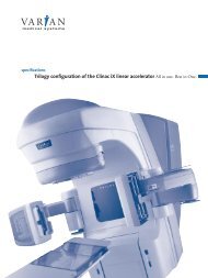
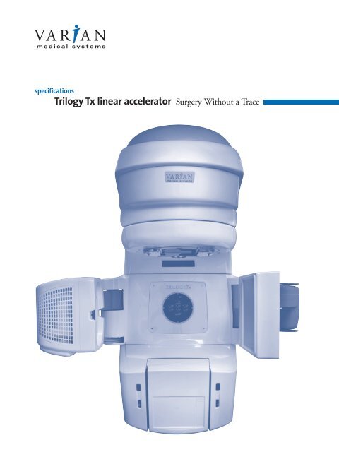
specifications<br />
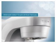
<strong>Trilogy</strong> Tx linear accelerator Surgery Without a Trace
<strong>Specification</strong>s<br />
Introduction<br />
This specification sheet provides information for the<br />
<strong>Trilogy</strong> Tx image-guided radiosurgery accelerator.<br />
Table 1: X-ray Beam Performance<br />
X-ray Beam Energy Combinations (MV)<br />
SRS Beam Beam I Beam II<br />
(BJR 17/BJR 11)<br />
6 6 10/10<br />
6 6 16/15<br />
6 6 23/18<br />
6 6 25/20<br />
1 Depth of ionization applies to 10 x 10 cm 2 field size<br />
measured at 100 cm Target-Skin Distance (TSD).<br />
2 Flatness is defined as the maximum variation from the<br />
mean dose delivered within the central 80% Full Width<br />
Half Maximum (FWHM) region measured at 100 cm TSD at<br />
a depth of 10 cm. The mean is the average of the maximum<br />
and minimum points within the central 80% FWHM<br />
region. The specification of ±2.5% applies to both the radial<br />
and transverse axes of all square field sizes from 20 x 20<br />
cm 2 to 40 x 40 cm 2 , inclusive. A specification of ±3.0%<br />
applies to all square field sizes between 10 x 10 cm 2 and 20<br />
x 20 cm 2 , and to 20 MV for all square field sizes larger than<br />
30 x 30 cm 2 . For the SRS 6MV beam, a specification of<br />
±3.0% applies to all square field sizes between 10 x 10 cm 2<br />
and 15 x 15 cm 2 .<br />
3 Symmetry is defined as the maximum difference between<br />
the X-ray dose delivered to any two points which are<br />
equidistant and symmetrical about the central axis and<br />
page 2<br />
1.0 Photon Beams<br />
1.1 Energy: Three photon beams may be selected in<br />
accordance with the specifications and<br />
combinations listed in Table 1.<br />
Nominal Nominal %Depth<br />
Energy (MV) Energy (MV) Dmax Dose at<br />
BJR 17 BJR 11 (cm) 1 10 cm Depth1 Flatness2 Symmetry3 SRS6 4 SRS6 4 1.60 ± 0.15 67.0 ± 1.0 ±3.0% 2.0%<br />
6 6 1.60 ± 0.15 67.0 ± 1.0 ±2.5% 2.0%<br />
10 10 2.40 ± 0.15 74.0 ± 1.0 ±2.5% 2.0%<br />
16 15 2.90 ± 0.15 77.0 ± 1.0 ±2.5% 2.0%<br />
23 18 3.30 ± 0.15 80.0 ± 1.0 ±2.5% 2.0%<br />
25 20 3.50 ± 0.15 81.5 ± 1.0 ±2.5% 2.0%<br />
within the central 80% FWHM region measured at 100 cm<br />
TSD at a depth of 10 cm. This specification applies to the<br />
radial and transverse axes of all square field sizes from 10 x<br />
10 cm 2 to 40 x 40 cm 2 . For the SRS 6 MV beam, this<br />
specification applies to the radial and transverse axes of all<br />
square field sizes from 10 x 10 cm 2 to 15 x 15 cm 2 .<br />
4 Beam matching between 6 MV Beam I and the SRS 6 MV<br />
beam is provided and defined as follows:<br />
4.1 The depth of Dmax along the central axis in a water<br />
phantom at 100 cm TSD is within ±1.5 mm of the<br />
average of the two beams. The relative dose at 10 cm<br />
depth on the central axis in a water phantom at 100 cm<br />
TSD is within ±0.5% of the average of the two beams.<br />
4.2 The dose at any point within the central 80% of the<br />
field along the major axes, normalized to the central<br />
axis, is within ±1 percentage point of the average of the<br />
two beams. This specification applies to beams at 10 cm<br />
depth and field dimensions of 10 x 10 cm 2 and above.<br />
Varian <strong>Trilogy</strong> Tx specifications
1.2 Dose Rate: For Beams I and II, the dose rate can<br />
be selected in fixed steps of 100 MU/min up to a<br />
maximum dose rate of 600 MU/min. For the<br />
SRS 6 MV Beam, the dose rate is 1,000<br />
MU/minute. The SRS high dose rate supports<br />
efficient delivery of stereotactic radiosurgery,<br />
stereotactic radiotherapy, and intensitymodulated<br />
radiation therapy (IMRT). Refer to<br />
section 12.0 for further information.<br />
Photon Energy (BJR17) Photon Dose Rate (MU/min)<br />
6-25 MV 100, 200, 300, 400, 500, 600<br />
SRS 6 MV 1000<br />
An “MU” is defined for these specifications as one cGy delivered<br />
to a tissue-equivalent material at Dmax and 100 cm SSD, with a<br />
10 x 10 cm 2 field size.<br />
1.3 Maximum Field Intensity at Dmax: The<br />
intensity at the depth of maximum buildup<br />
(Dmax) does not exceed 109% of the central<br />
axis intensity anywhere in the measurement<br />
plane of any field size.<br />
1.4 Leakage: The X-ray absorbed dose does not<br />
exceed 0.1% of the absorbed dose at the<br />
isocenter measured anywhere in the patient<br />
plane outside of the maximum useful beam.<br />
The neutron dose equivalent (Sievert) does not<br />
exceed 0.2% of the X-ray absorbed dose<br />
(Gray) at the isocenter.<br />
The patient plane is defined as a circular plane<br />
with a radius of 2 m, centered on and<br />
perpendicular to the axis of the beam at<br />
isocenter. The X-ray measurements may be<br />
averaged over an area not to exceed 100 cm2 .<br />
In all other directions, the X-ray absorbed dose<br />
at 1 m from the path of the electrons between<br />
the electron gun and the target or electron<br />
window does not exceed 0.1% of the absorbed<br />
dose at isocenter.<br />
1.5 Collimator Transmission: The X-ray transmission<br />
of the upper and lower movable collimator does<br />
not exceed 0.5%.<br />
page 3<br />
1.6 Spot Size: The electron spot size is less than<br />
3 mm in diameter at the X-ray target.<br />
1.7 Penumbra: The distance between the 20% and<br />
80% isodose lines for a 10 x 10 cm2 field,<br />
measured at a depth of 10 cm with a 100 cm<br />
TSD along the major axes, measures less than or<br />
equal to 9 mm.<br />
1.8 Field Size: The field size is continuously variable<br />
from 0.5 x 0.5 cm2 to 40 x 40 cm2 as measured<br />
at 100 cm TSD. Field sizes larger than 35 x<br />
35 cm2 are limited to a 49.5 cm diagonal (the<br />
diameter of the circle defined by the primary<br />
collimator at 100 cm TSD). The field size is<br />
defined as the distance along the radial and<br />
transverse axes between the points of 50%<br />
density on an X-ray film taken at 100 cm TSD<br />
with minimum buildup. The SRS 6 MV beam<br />
field size is limited to a maximum of<br />
15 x 15 cm2 .<br />
1.9 Upper and Lower Independent Collimators:<br />
Asymmetrical collimation is provided for upper<br />
and lower sets of collimators.<br />
1.9.1 Independent, asymmetrical Upper<br />
Collimator travel range: 30 cm (-10 cm<br />
to +20 cm relative to central axis)<br />
1.9.2 Independent, asymmetrical Lower<br />
Collimator travel range: 22 cm (-2 cm to<br />
+20 cm relative to central axis)<br />
2.0 Electron Beams Option<br />
2.1 <strong>Trilogy</strong> Tx offers a range of six (6) optional<br />
electron beams that can be selected in accordance<br />
with the specifications and combinations listed in<br />
Table 2. The specifications apply to a 15 x 15<br />
cm2 electron applicator and 100 cm TSD.<br />
2.2 Dose Rate:<br />
Electron Dose Rate (MU/min)<br />
100, 200, 300, 400, 500, 600, 1000<br />
888 at 1.6 m (choose either 6 MeV or 9 MeV)<br />
A high electron dose rate is available at 6 MeV or 9 MeV electron<br />
energy. Refer to section 8.1 for further information.<br />
Varian <strong>Trilogy</strong> Tx specifications
2.3 Field Sizes: A set of five electron applicators<br />
can be provided, with selection from 6 sizes:<br />
6 x 6 cm 2 , 6 x 10 cm 2 , 10 x 10 cm 2 ,<br />
15 x 15 cm 2 , 20 x 20 cm 2 , and 25 x 25 cm 2 .<br />
Table 2: Electron Beam Performance<br />
Electron Energy Groups<br />
Nominal Electron Energy (MeV)<br />
Group I 4, 6, 9, 12, 15, 18<br />
Group II 6, 9, 12, 15, 18, 22<br />
Group III 4, 6, 9, 12, 16, 20<br />
1 Depth of Ionization values apply to 15 x 15 cm 2 applicator<br />
field size. Electron measurements are made at 100 cm TSD<br />
and a nominal 5 cm gap between the bottom of the open<br />
field aperture and the water surface. Measurements are<br />
defined with a 0.1 cm 3 PTW ionization chamber, or<br />
equivalent.<br />
2 D85%/2 is the depth at which flatness and symmetry are<br />
specified. Values are defined at 100 cm TSD using a 15 x 15<br />
cm 2 electron applicator field size. No inverse square<br />
corrections are assumed.<br />
3 Flatness is defined as the maximum variation from the<br />
mean electron ionization within the central 80% FWHM<br />
region. The mean is the average of the maximum and<br />
minimum points within the central 80% FWHM region.<br />
page 4<br />
Field sizes are defined at the isocenter plane, 5 cm<br />
from the final field-defining aperture. Hardware is<br />
provided to facilitate the fabrication of custom final<br />
field defining apertures.<br />
Depth of Ionization1 Depth of Dose Value<br />
Nominal 90% 80% 50% 30% 85%/2 80% Flatness3 Symmetry4 Energy (cm) (cm) (cm) (cm) (cm) 2 (cm) (MU/min)<br />
4 .89 1.00 1.26 ≤2.00 0.61 1.00 ±7% 2%<br />
±0.1 ±0.07 ±0.1<br />
6 1.71 1.90 2.30 ≤2.60 0.93 1.95 ±4.5% 2%<br />
±0.1 ±0.07 ±0.1<br />
9 2.68 2.95 3.50 ≤3.90 1.45 3.00 ±4.5% 2%<br />
±0.1 ±0.07 ±0.1<br />
12 3.77 4.15 4.89 ≤5.40 2.02 4.25 ±4.5% 2%<br />
±0.1 ±0.07 ±0.1<br />
15 4.68 5.20 6.17 ≤6.80 2.57 5.35 ±4.5% 2%<br />
±0.1 ±0.07 ±0.1<br />
16 4.87 5.45 6.49 ≤7.30 2.67 5.60 ±4.5% 2%<br />
±0.1 ±0.07 ±0.1<br />
18 5.31 6.10 7.41 ≤8.15 3.04 6.40 ±4.5% 2%<br />
±0.1 ±0.07 ±0.1<br />
20 5.52 6.55 8.13 ≤9.30 3.26 6.90 ±4.5% 2%<br />
±0.1 ±0.07 ±0.1<br />
22 5.59 6.80 8.64 ≤10.00 3.37 7.20 ±4.5% 2%<br />
±0.1 ±0.07 ±0.1<br />
This specification applies to square electron applicator field<br />
sizes from 10 x 10 cm 2 to 25 x 25 cm 2 measured on the<br />
radial and transverse axes. A specification of ±5% is applied<br />
to 6 MeV for 10 x 10 cm 2 applicator field size. The diagonal<br />
flatness specification for the above applicator field sizes is<br />
±5%, except 4 MeV. The 4 MeV flatness specification<br />
applies only to the radial and transverse axes.<br />
4 Symmetry is defined as the maximum difference between<br />
the ionization delivered to any two points that are<br />
equidistant and symmetrical about the central axis and<br />
within the central 80% FWHM region. This specification<br />
applies to the plane normal to the central axis and to<br />
square electron applicator field sizes from 10 x 10 cm 2 to<br />
25 x 25 cm 2 , except 4 MeV. The 4 MeV specification applies<br />
only to the radial and transverse axes.<br />
Varian <strong>Trilogy</strong> Tx specifications
2.4 X-ray Contamination: For nominal energies up<br />
to 10 MeV, the X-ray contamination is less than<br />
or equal to 2%. For nominal energies greater<br />
than 10 MeV, the X-ray contamination is less<br />
than or equal to 5%. This specification is defined<br />
in water with a 100 cm TSD, at a depth of<br />
10 cm beyond the depth of the 10% isodose<br />
line, with a 15 x 15 cm2 electron applicator.<br />
2.5 Patient Plane Leakage: Electron leakage is less<br />
than or equal to 2% of the absorbed dose on<br />
central axis. This specification is defined in air, at<br />
100 cm TSD with 1 cm buildup, in an area<br />
4 cm outside the 50% isodose line.<br />
2.6 Applicator Side Plane Leakage: The leakage<br />
does not exceed 9% of central axis ionization<br />
at Dmax. This specification is defined along a<br />
plane coincident to the side of the electron<br />
applicator, measuring 10 cm up from the<br />
bottom of an applicator.<br />
3.0 Accelerator System Features<br />
3.1 RF Power Source: Varian’s high-efficiency<br />
klystron is operated in linear amplifier mode and<br />
driven by a solid-state oscillator, with power and<br />
frequency automatically locked to required<br />
operating levels.<br />
3.2 Electron Gun: The unique triode design of the<br />
electron gun allows exact and safe control of<br />
electron beam levels in the accelerator. It<br />
provides the ability to rapidly and precisely<br />
vary output dose rate and turn the beam on or<br />
off. This capability is especially important in<br />
dynamic dose delivery, where high-speed beam<br />
gating and elimination of dark current during<br />
beam-off time periods is important. The gun is<br />
demountable, resulting in minimum system<br />
downtime during replacement.<br />
3.3 Standing Wave Accelerator: The Varian sidecoupled<br />
cavity accelerator structure has been<br />
developed for optimum use of RF power and<br />
narrow output spectrum at the design energy<br />
for the guide. Spectrum characteristics, with<br />
and without use of an energy switch, have<br />
been matched to the transport requirements of<br />
the downstream bend magnet to ensure high<br />
dose rate capability.<br />
3.4 Patented Non-Contacting Energy Switch: In<br />
each of the X-ray treatment modes where this is<br />
page 5<br />
utilized, the switch functions to change the ratio<br />
of electric fields between two sections of the<br />
accelerator guide. This is done in such a way as<br />
to ensure a tight energy spectrum over a wide<br />
range of photon energies, with consequent high<br />
output capability and stable operation.<br />
3.5 Solenoid: A full-length magnetic solenoid assures<br />
high electron beam transmission through the<br />
accelerator structure, resulting in reduced strayradiation<br />
and efficient use of RF power.<br />
3.6 Bend Magnet: The patented 270° bend<br />
magnet is fully achromatic, with one-to-one<br />
imaging for superior transport and control of<br />
the beam from the accelerator. The magnet is<br />
also equipped with energy slits fixed at ±3%,<br />
enabling output beams of consistently high<br />
quality and precise dosimetry.<br />
3.7 Radial and Transverse Steering Systems: These<br />
systems ensure basic beam alignment in all<br />
modes, as well as gantry orientation. Ion<br />
chamber sensors, in conjunction with the<br />
steering coils and servo electronics, maintain<br />
beam symmetry changes to within 2% under<br />
all foreseeable conditions.<br />
4.0 Dosimetry System<br />
The following specifications apply for both<br />
independent dosimetry channels:<br />
4.1 Reproducibility with Energy: Precision of the<br />
dosimetry measurement system for each energy is<br />
±1% or ±1 MU, whichever is greater, at a fixed<br />
dose rate.<br />
4.2 Dose Calibration Linearity versus Total Dose:<br />
The linearity is as follows:<br />
• 1% for 20-999 MU<br />
• 2% for 10-20 MU<br />
• 3% for 5-10 MU<br />
4.3 For photon Beams I and II, doses up to<br />
999 MU per field can be delivered. For the SRS<br />
6 MV Beam, doses up to 6,000 MU can be<br />
delivered.<br />
For all electron beams, doses up to 4,000 MU<br />
can be delivered. (Optional)<br />
4.4 Reproducibility of Dose vs. Gantry Angle: The<br />
precision of the dosimetry system is ±1.5% at<br />
any gantry angle from 0 to 360 degrees.<br />
Varian <strong>Trilogy</strong> Tx specifications
4.5 Reproducibility with Dose vs. Dose Rate: The<br />
dose rate dependence of the dosimetry system<br />
with variations in dose rate from minimum to<br />
maximum is less than ±1% or ±1 MU,<br />
whichever is greater.<br />
4.6 Beam-Off Interlocks: The radiation beam<br />
automatically terminates in the event of any of<br />
the following:<br />
• Monitor Units 1 complete<br />
• Monitor Units 2 complete<br />
• Treatment time complete<br />
• Radial symmetry exceeds 2%<br />
• Transverse symmetry exceeds 2%<br />
• Excess dose rate<br />
• Excess dose per pulse<br />
• Excess dose per degree<br />
• Loss of ion chamber bias voltage<br />
• Under dose rate<br />
5.0 Beam Matching Option<br />
Beam matching of a new <strong>Trilogy</strong> Tx accelerator to<br />
existing high-energy Clinac ® iX linear accelerators,<br />
and low- and high-energy Clinac EX accelerators that<br />
meet the serial number requirements shown below is<br />
available as a purchasable option. If purchased, this<br />
option includes on-site demonstration of the matched<br />
beams as described below.<br />
Basic or Fine Beam Matching to existing accelerator<br />
systems installed outside a 1-year time frame may be<br />
available as a purchasable option (refer to section 5.3).<br />
5.1 Restrictions and Definitions<br />
5.1.1 All specifications apply to fields measured<br />
in water with the surface 100 cm from<br />
the target of the accelerator system.<br />
5.1.2 Dmax is the depth at which the maximum<br />
dose occurs along the central axis of the<br />
beam for a 10 x 10 cm2 X-ray field.<br />
5.1.3 R85/2 is one-half the depth where 85%<br />
relative ionization occurs on the central<br />
axis of an electron field using the 15 x<br />
15 cm2 applicator.<br />
page 6<br />
Varian <strong>Trilogy</strong> Tx specifications<br />
5.1.4 Major axes lines orthogonal to the central<br />
axis of the beam and perpendicular to the<br />
sides of rectangular fields.<br />
5.1.5 The term “average” is defined as the<br />
average value for the referenced<br />
performance specification, calculated<br />
using measurements obtained from the<br />
new <strong>Trilogy</strong> Tx accelerator and the<br />
existing accelerator systems(s) to which it<br />
is matched.<br />
5.2 On-Site Demonstration of Matched Beams<br />
5.2.1 Basic Photon Beam Matching, per beam<br />
5.2.1.1 Basic Matching of Photon<br />
X-Ray Beam Energy: For each<br />
X-ray beam of the same<br />
nominal energy, the depth of<br />
Dmax along the central axis in<br />
a water phantom at 100 cm<br />
TSD is within ±1.5 mm of the<br />
average. For each X-ray beam<br />
of the same nominal energy,<br />
the relative dose at 10 cm<br />
depth on the central axis in a<br />
water phantom at 100 cm<br />
TSD (normalized to the dose<br />
at Dmax) is within ±1.0% of<br />
the average.<br />
5.2.1.2 Basic Matching of Photon<br />
X-Ray Beam Flatness: For<br />
X-ray beams of the same<br />
nominal energy, the maximum<br />
dose in the plane normal to the<br />
beam axis at a depth of Dmax in<br />
water at 100 cm TSD is within<br />
±1% of the average. For each<br />
beam of the same nominal<br />
energy, the dose at any point<br />
within the central 80% of the<br />
in-plane and cross-plane axes,<br />
normalized to the central axis,<br />
measured at a depth of 10 cm<br />
in water at a TSD of 100 cm is<br />
within ±2% of the average for<br />
the measured values at that<br />
point. This specification applies<br />
to X-rays at 10 cm depth and<br />
field dimensions greater than<br />
10 x 10 cm2 .
5.2.2 Basic Electron Beam Matching, per<br />
beam<br />
5.2.2.1 Basic Matching of Electron<br />
Beam Energy: For each electron<br />
beam of the same nominal<br />
energy, the relative ionization at<br />
100 cm TSD, the depth of<br />
90%, 80%, and 50%, is within<br />
±1.0 mm of the average. This<br />
specification applies to the 15 x<br />
15 cm2 applicator.<br />
5.2.2.2 Basic Matching of Electron<br />
Beam Flatness: Basic matching<br />
of electron beams does not<br />
include flatness.<br />
5.2.3 Fine Photon Beam Matching, per beam<br />
5.2.3.1 Fine Matching of Photon<br />
X-Ray Beam Energy: For each<br />
X-ray beam of the same<br />
nominal energy, the depth of<br />
Dmax along the central axis in<br />
water phantom at 100 cm<br />
TSD is within ±1.5 mm of the<br />
average. For each X-ray beam<br />
of the same nominal energy,<br />
the relative dose at 10 cm<br />
depth on the central axis in a<br />
water phantom at 100 cm<br />
TSD (normalized to the dose<br />
at Dmax) is within ±0.5% of<br />
the average.<br />
5.2.3.2 Fine Matching of Photon<br />
X-Ray Beam Flatness: For<br />
X-ray beams of the same<br />
nominal energy, the maximum<br />
dose in the plane normal to the<br />
beam axis at a depth of Dmax in<br />
water at 100 cm TSD is within<br />
±1% of the average. For each<br />
beam of the same nominal<br />
energy, the dose at any point<br />
within the central 80% of the<br />
in-plane and cross-plane axes,<br />
normalized to the central axis,<br />
measured at a depth of 10 cm<br />
in water at a TSD of 100 cm is<br />
within ±2% of the average.<br />
page 7<br />
Varian <strong>Trilogy</strong> Tx specifications<br />
This specification applies to<br />
X-rays at 10 cm depth and field<br />
dimensions greater than 10 x<br />
10 cm2 .<br />
5.2.4 Fine Electron Beam Matching, per beam<br />
5.2.4.1 Fine Matching of Electron<br />
Beam Energy: For each electron<br />
beam of the same nominal<br />
energy, the relative ionization<br />
values of 90%, 80%, and 50%<br />
at 100 cm TSD, are within<br />
±1.0 mm of the average. This<br />
specification applies to the 15 x<br />
15 cm2 applicator.<br />
5.2.4.2 Fine Matching of Electron<br />
Beam Flatness: For each beam<br />
of the same nominal energy, the<br />
ionization at any point within<br />
the central 80% of the in-plane<br />
and cross-plane scans,<br />
normalized to the central axis,<br />
measured at the depth of Dmax in water at a TSD of 100 cm is<br />
within ± 2% of the average of<br />
the measured values at that<br />
point. This specification applies<br />
to the 25 x 25 cm2 and 10 x<br />
10 cm2 applicators.<br />
5.3 Beam Matching to Accelerator Systems Installed<br />
Outside a 1-Year Time Frame<br />
5.3.1 Basic or Fine Beam Matching, including<br />
on-site demonstration, of a new <strong>Trilogy</strong><br />
Tx accelerator to existing accelerator<br />
systems installed outside a 1-year time<br />
frame is available as a purchasable option<br />
for accelerator systems that meet the<br />
following requirements:<br />
• Clinac iX, all serial numbers<br />
• <strong>Trilogy</strong> Tx, all serial numbers<br />
• Low-energy Clinacs, serial number 244<br />
and higher<br />
• Clinac 21 series, serial number 865<br />
and higher<br />
• Clinac 23 series, serial number 144<br />
and higher
• Silhouette edition Clinacs, all serial<br />
numbers<br />
5.3.2 Basic or Fine Beam Matching, including<br />
on-site demonstration, of a new <strong>Trilogy</strong><br />
Tx accelerator to existing accelerator<br />
systems that do not meet the serial<br />
number requirements above may be<br />
available as a purchasable option.<br />
6.0 Mechanical Features<br />
6.1 Gantry<br />
6.1.1 Rotation Range: ±185° from the vertical<br />
6.1.2 Target to Axis Distance: 100 ±0.2 cm<br />
6.1.3 Mechanical and radiation isocenter<br />
accuracy<br />
6.1.3.1 <strong>Trilogy</strong> Tx not available with<br />
Retractable Beam Stopper<br />
6.1.3.2 Requires 52-inch Exact Couch base frame<br />
6.1.3.3 ≤0.5 mm radius sphere for<br />
gantry and collimator axes<br />
6.1.3.4 ≤0.75 mm radius sphere for<br />
gantry, collimator, and couch<br />
axes<br />
6.1.4 Position Indicators (gantry and console)<br />
<strong>Trilogy</strong> Tx Dimensions<br />
1260<br />
(126 cm)<br />
(49.6")<br />
1070<br />
(107 cm)<br />
(42")<br />
433<br />
(43.3 cm)<br />
(17")<br />
1295<br />
(129.5 cm)<br />
(51")<br />
page 8<br />
1832<br />
(183.2 cm)<br />
(72")<br />
552<br />
(55.2 cm)<br />
(21.7")<br />
Varian <strong>Trilogy</strong> Tx specifications<br />
6.1.4.1 IEC Scale convention (IEC<br />
601 or 1217 compliant) or<br />
Varian Scale may be used for<br />
position readouts.<br />
6.1.4.2 Digital Readouts:<br />
• Accuracy: ±0.5°<br />
• Resolution: 0.1°<br />
6.1.4.3 Mechanical Scales:<br />
• Accuracy: ±1.0°<br />
• Resolution: 1.0°<br />
6.1.4.4 Gantry Display Only:<br />
Enhanced Dynamic Wedge (EDW) beam modulation<br />
graphic indicator shows that<br />
EDW is enabled in either Y1 or<br />
Y2 direction.<br />
6.1.5 Target to Surface Distance Indicators<br />
6.1.5.1 Optical Distance Indicator:<br />
• Accuracy: ±0.1 cm at 100 cm,<br />
and ±0.5 cm at 70 cm and<br />
156 cm<br />
• Resolution: 0.5 cm<br />
6.1.5.2 Mechanical Front Pointer:<br />
• Range: 70-110 cm<br />
• Accuracy: ±0.1 cm at 100 cm<br />
• Resolution: 0.2 cm<br />
2008<br />
(200.8 cm)<br />
(79")<br />
3236<br />
(323.6 cm)<br />
(127.4")<br />
32<br />
(3.2 cm)<br />
(1.25")<br />
Illustration not to scale<br />
2584<br />
(258.4 cm)<br />
(102")
6.1.6 Isocenter Height (nominal): 129.5 cm<br />
6.2 Collimator<br />
6.2.1 Extended Rotation Range: ±165°<br />
6.2.2 Mechanical Isocenter Accuracy:<br />
≤0.05 cm radius from isocenter<br />
6.2.3 Position Indicators (gantry and console)<br />
6.2.3.1 Digital Readouts:<br />
• Accuracy: ±0.5°<br />
• Resolution: 0.1°<br />
6.2.3.2 Mechanical Scales:<br />
• Accuracy: ±1.0°<br />
• Resolution: 1.0°<br />
6.3 Field Size Collimation<br />
6.3.1 Range: The field size is continuously<br />
variable from 0.5 x 0.5 cm2 to 40 x<br />
40 cm2 as measured at 100 cm TSD.<br />
Field sizes larger than 35 x 35 cm2 are<br />
limited to a 49.5 cm diagonal (the<br />
diameter of the circle defined by the<br />
primary collimator at 100 cm TSD).<br />
The field size is defined as the distance<br />
along the radial and transverse axes<br />
between the points of 50% density on<br />
an X-ray film taken at 100 cm TSD with<br />
minimum buildup. The SRS 6 MV<br />
beam field size is limited to a maximum<br />
of 15 x 15 cm2 .<br />
6.3.2 Position Indicators<br />
• Accuracy: ±0.2 cm<br />
• Resolution: 0.1 cm<br />
6.3.3 Light and X-ray Field Coincidence: The<br />
field-defining light coincides to within<br />
1.5 mm of the 50% isodensity line on<br />
an X-ray film. This is defined at 100 cm<br />
TSD with minimum buildup for any<br />
field size.<br />
6.4 Exact ® Couch with Indexed Immobilization 6.4.1 The Exact Couch is standard with<br />
<strong>Trilogy</strong> Tx. (<strong>Specification</strong>s and standard<br />
vs. optional accessories for the Exact<br />
Couch are provided on Exact Couch<br />
specification sheet, RAD 1951.)<br />
page 9<br />
6.4.2 Motion Controls<br />
• Two Hand Pendants that control the<br />
accelerator and Exact Couch<br />
• Two Couch Side Panels<br />
• Remote Couch Control<br />
6.4.3 Position Indicators<br />
• Corrective motions: small translations<br />
(in x, y, and z) and small rotation of<br />
the couch to fine tune patient setups<br />
• Planned motions: large rotations of the<br />
couch to sequence between noncoplanar<br />
fields and arcs<br />
6.4.3.1 Translation<br />
• Accuracy: ±0.1 cm<br />
• Resolution: 0.1 cm<br />
6.4.3.2 Rotation<br />
• Accuracy: ±0.5°<br />
• Resolution: 0.1°<br />
6.5 Compact stand assembly<br />
6.5.1 Single access and through-door viewing<br />
of all gas and water system status<br />
indicators<br />
6.5.2 Imager electronics (PortalVision MV<br />
imaging system and On-Board Imager kV imaging system) incorporated in<br />
reduced height stand<br />
7.0 Mechanical Accessories Options<br />
The following optional accessories are available with<br />
<strong>Trilogy</strong> Tx and the Exact Couch:<br />
7.1 Collimator Accessories:<br />
• Interface Mount<br />
• Accessory Mount<br />
• Port Film Graticule<br />
• 4-Way Wedge Set (four wedges 15°, 30°,<br />
45°, 60°)<br />
• Optional Electron Applicators: A set of<br />
five electron applicators can be provided, with<br />
selection from 6 sizes: 6 x 6 cm2 , 6 x 10 cm2 ,<br />
10 x 10 cm2 , 15 x 15 cm2 , 20 x 20 cm2 , and<br />
25 x 25 cm2 .<br />
Varian <strong>Trilogy</strong> Tx specifications
• Custom Aperture Fabrication Hardware<br />
• Mechanical Front Pointer (holder and 4 rods)<br />
• Drilled Star trays (Qty 10 - 0.635 cm<br />
thickness)<br />
• Slotted Block trays (Qty 2 - 0.635 cm<br />
thickness)<br />
7.2 Accessory Spare Parts Kit<br />
8.0 Basic Static Procedures Mode Option<br />
8.1 High Dose Total Skin Electron Mode: <strong>Trilogy</strong><br />
Tx is capable of delivering electron treatments<br />
at high dose rates for the purpose of total skin<br />
irradiation. The dose rate at 1.6 m is 888<br />
MU/min, corresponding to nominally 2,500<br />
MU at isocenter. This mode is available in 6<br />
MeV or 9 MeV.<br />
8.1.1 X-ray contamination at calibration point<br />
is
If these tolerances are exceeded, the dose<br />
delivery is suspended and the gantry<br />
position is targeted to the position<br />
dictated by the actual dose delivered.<br />
When the gantry is again within 0.5<br />
degrees of the desired position, the<br />
treatment will resume. The Dose<br />
Position Interlock (DPSN) is asserted if<br />
the gantry is not positioned within<br />
0.5 cm of the desired position within<br />
3 seconds.<br />
The DPSN will terminate the beam<br />
immediately if the position deviates 3.0<br />
degrees or more from the desired<br />
position, or the dose delivered exceeds<br />
0.45 MU.<br />
10.1.2 Arc Dose Rate: The dose rate during a<br />
dynamic arc treatment is automatically<br />
modulated between zero and the ceiling<br />
dose rate selected in Physics Mode.<br />
10.1.3 Arc Direction: <strong>Trilogy</strong> Tx may be<br />
programmed to perform arc therapy in<br />
either a clockwise or counterclockwise<br />
direction.<br />
10.2 Enhanced Dynamic Wedge (EDW) Mode:<br />
EDW can be used with either Beam I or Beam<br />
II. EDW utilizes Y-jaws to create wedge shaped<br />
dose distributions. Enhanced Dynamic Wedges<br />
of 10, 15, 20, 25, 30, 45, and 60 degrees are<br />
included, with up to 30 cm (wedge direction) by<br />
40 cm field sizes. (Refer to Enhanced Dynamic<br />
Wedge <strong>Specification</strong>, RAD 1880.)<br />
11.0 Advanced Dynamic Techniques<br />
Intensity-modulated radiation therapy (IMRT) and<br />
conformal arc therapy are advanced dynamic<br />
techniques in which the leaves of the Millennium<br />
MLC move during treatment. Refer to DMLC<br />
<strong>Specification</strong>, RAD 5610 for additional information<br />
and specifications.<br />
11.1 Arc Dynamic MLC allows delivery of MLC<br />
fields as a function of gantry arc angle, also<br />
known as conformal arc therapy. An MLC shape<br />
change every 2° is supported.<br />
page 11<br />
11.2 Dose Dynamic MLC allows delivery of MLC<br />
fields as a function of percent dose delivered,<br />
also known as IMRT. Both dynamic IMRT<br />
(i.e., sliding window) and segmental IMRT<br />
(i.e., step-and-shoot) techniques are supported.<br />
Combinations of the two IMRT techniques also<br />
are supported. In addition, Dose Dynamic<br />
MLC enables treatment delivery with electronic<br />
compensation, in which MLC leaf motion<br />
simulates the dosimetric effect of a physical<br />
compensator.<br />
12.0 Stereotactic Mode<br />
<strong>Trilogy</strong> Tx is capable of delivering stereotactic<br />
treatments at high dose rates and with remote couch<br />
motion. This mode is available with 6 MV photons.<br />
Both cone- and MLC-based treatment delivery are<br />
supported. Beam flatness, symmetry, and other<br />
specifications can be found in Table 1.<br />
12.1 Dose Rate: 1,000 MU per minute at Dmax at<br />
100 cm TSD<br />
12.2 Maximum dose per field: 6,000 MU<br />
12.3 Maximum field size: 15 x 15 cm2 12.4 Maximum dose per degree for arc treatments:<br />
60 MU per degree<br />
12.5 Stereotactic Motion Disable<br />
12.5.1 Mechanical couch locks<br />
12.5.2 Electrical disable for gantry and couch<br />
13.0 Stereotactic Components<br />
Choose either the Varian or BrainLAB package of<br />
stereotactic components. Each package includes:<br />
• Conical collimators for circular arc treatments and<br />
collimator mount<br />
• Stereotactic headring (two headrings included with<br />
the Varian package) and couch mount<br />
• Frameless stereotactic intracranial immobilization<br />
• Stereotactic treatment planning capability for cones<br />
and the Millennium 120-leaf MLC<br />
• Optical Guidance Platform with the FrameArray and FramelessArray optically guided cranial SRS<br />
positioning and BodyArray optically guided<br />
extracranial SRS system (available only with the<br />
Varian package)<br />
Varian <strong>Trilogy</strong> Tx specifications
14.0 Millennium 120-Leaf Multileaf Collimator<br />
The Millennium 120-leaf MLC offers 0.5 cm leaf<br />
resolution at isocenter for the central 20 cm of the 40<br />
cm x 40 cm field. The Millennium MLC operates in<br />
static, dynamic, and conformal arc modes. The static<br />
mode provides efficient beam shaping for 3D<br />
conformal radiation therapy. The dynamic mode<br />
enables IMRS with both step-and-shoot and sliding<br />
window delivery. The conformal arc mode enables<br />
conformal arc therapy in which the leaves always<br />
conform to the outer boundary of the target as the<br />
gantry rotates around the patient.<br />
Refer to MLC RAD 5609 for additional MLC<br />
information and specifications.<br />
15.0 On-Board Imager Patient Positioning and<br />
Target Localization System<br />
The On-Board Imager provides high-quality kV<br />
images in the treatment room for target localization,<br />
patient positioning, and motion management. The<br />
following clinical capabilities are supported:<br />
• Acquisition of cone-beam CT scans<br />
• Online setup correction based on either a kV-kV or<br />
kV-MV pair of radiographs<br />
• Automated and manual alignment of a pair of<br />
radiographs to their reference images<br />
• Acquisition of gated radiographs<br />
• Online setup correction based on radiopaque<br />
markers<br />
• Pretreatment verification of gated treatment portals<br />
using kV fluoroscopy<br />
• Robotic arms to position and hold the kV source<br />
and kV digital detection<br />
• Remote couch motion to correct patient setups<br />
Refer to On-Board Imager <strong>Specification</strong>, RAD 9502,<br />
for information and specifications.<br />
16.0 PortalVision aS1000 MV Imaging System<br />
The PortalVision aS1000 is an MV imaging system<br />
that allows for verification of patient setups, treatment<br />
portals, and pre-treatment QA.<br />
The amorphous silicon detector has an active<br />
imaging area of 40 cm x 30 cm with a pixel<br />
resolution of 1024 x 768. Image acquisition is<br />
supported before, during, and after treatment.<br />
Match and Review software is included for<br />
image analysis.<br />
page 12<br />
A motorized, retractable robotic arm is used to<br />
position and hold the detector.<br />
Refer to PortalVision aS1000 <strong>Specification</strong>, RAD<br />
2553, for information and specifications.<br />
17.0 Portal Dosimetry<br />
Portal Dosimetry enables use of the PortalVision<br />
imager to record the intensity patterns of IMRT fields<br />
for pretreatment quality assurance of IMRT planning<br />
and delivery.<br />
Portal Dosimetry includes integrated image<br />
acquisition mode for recording of IMRT fields and<br />
image viewing and analysis software. (*Use of the<br />
image analysis software is optimized when the<br />
reference dose image is calculated as dose to<br />
amorphous silicon. Currently, only the Eclipse integrated treatment planning system offers<br />
this capability.)<br />
Refer to PortalVision aS1000 <strong>Specification</strong>, RAD<br />
2553, for additional information and specifications.<br />
18.0 RPM Respiratory Gating System<br />
The RPM respiratory gating system enables passive,<br />
real-time monitoring of patient motion for the<br />
purpose of intrafraction motion management. Two<br />
gating systems are provided. Each system includes an<br />
optical tracking camera, external marker block, and<br />
RPM respiratory gating system workstation. The<br />
RPM respiratory gating system supports gated<br />
treatment delivery and image acquisition on the<br />
accelerator, gated simulation on compatible<br />
simulators (not all simulators are supported), and<br />
gated CT acquisition on compatible third-party CT<br />
scanners (not all CT scanners are compatible).<br />
Depending on the capabilities of the CT scanner, the<br />
RPM respiratory gating system supports both<br />
retrospective and prospective gating of CT scans.<br />
Refer to RPM Respiratory Gating System<br />
<strong>Specification</strong>, RAD 5616 for additional information.<br />
19.0 LaserGuard Collision Detection System<br />
LaserGuard monitors the MLC collimator face with<br />
a plane of infrared light that emanates from a device<br />
located within the gantry. Any object that intrudes<br />
into this area, called the protection zone, triggers an<br />
emergency stop of all accelerator motion.<br />
Varian <strong>Trilogy</strong> Tx specifications
Refer to Auto Field Sequencing with LaserGuard<br />
<strong>Specification</strong>, RAD 6046 for information and<br />
specifications.<br />
20.0 Argus QA Software<br />
Argus provides powerful software tools for<br />
automation of quality assurance data acquisition,<br />
data analysis, visual display of data, and reporting.<br />
Argus also provides a centralized database for digital<br />
storage of data.<br />
The Argus QA software provides quality assurance<br />
modules for linear accelerators, including static and<br />
dynamic MLC using DynaLog file analysis, CT<br />
simulators, standard simulators, film processors,<br />
and HDR brachytherapy systems.<br />
21.0 Factory Beam Data Set<br />
The Factory Beam Data Set is provided in hard<br />
copy and ASCII file formats. The data include<br />
machine mechanical parameters and representative<br />
beam data. The data set is not a substitute for the<br />
commissioning process but an aid to speed that<br />
process as well as data entry to treatment planning<br />
systems. The factory data are representative of the<br />
<strong>Trilogy</strong> Tx accelerator manufacturing standard, not<br />
the specific machine delivered.<br />
22.0 SmartConnect Remote Access<br />
Technology<br />
SmartConnect remote access technology connects<br />
the <strong>Trilogy</strong> Tx accelerator with Varian Customer<br />
Support for expert assistance and online remote<br />
analysis. Diagnostic and Morning Checkout Logs<br />
can be viewed remotely and transferred to Varian for<br />
report generation and trend analysis.<br />
23.0 Treatment Command Center<br />
23.1 The 4D Integrated Treatment Console provides<br />
a streamlined front end to the <strong>Trilogy</strong> Tx<br />
accelerator. The console integrates use of the<br />
accelerator, Millennium MLC, and<br />
PortalVision MV imaging system into one<br />
application on a single workstation. For imageguided<br />
radiosurgery and radiotherapy using kV<br />
images, the console is used in combination with<br />
the On-Board Imager workstation. The 4D<br />
Integrated Treatment Console uses a DICOM<br />
RT interface to communicate with the ARIA oncology information system and other<br />
information system databases.<br />
page 13<br />
23.2 Ergonomic command center configuration<br />
places all control modules, monitors, and user<br />
interaction devices within easy reach of the<br />
operator. Direct access application selection<br />
simplifies the workspace by reducing the<br />
number of input devices (e.g., keyboard and<br />
mouse), while allowing continuous viewing of<br />
all applications.<br />
24.0 In-Room Display<br />
A high-resolution, flat screen, color display monitor is<br />
included for in-room display of accelerator parameters<br />
and patient-specific information.<br />
25.0 Typical Facility Requirements<br />
25.1 Electrical Requirements<br />
25.1.1 Typical 60Hz: 200-240 VAC, line-toline,<br />
3-phase, 4-wire plus ground,<br />
45 KVA load.<br />
25.1.2 Typical 50Hz: 360-440 VAC, line-toline,<br />
3-phase, 4-wire plus ground,<br />
45 KVA load.<br />
25.2 Cooling Water Requirements: The cooling water<br />
requirements can be satisfied with a one-pass<br />
system (domestic supply and waste return) or a<br />
closed loop system.<br />
25.3 Ventilation must be sufficient to remove 8 kW<br />
from treatment room and 1 kW from control<br />
console.<br />
25.4 Compressed Air Requirements: Instrument<br />
quality air is required.<br />
25.5 On-Board Imager Power Requirements<br />
25.5.1 Input voltage: 400 to 480 Vac (±10%),<br />
3-phase, 4-wire plus ground<br />
25.5.2 Input frequency: 50 or 60 Hz (±1%)<br />
25.5.3 For comprehensive facilities<br />
requirements refer to the On-Board<br />
Imager Installation Data Package.<br />
For detailed facilities requirements refer to the <strong>Trilogy</strong><br />
Tx Installation Data Package.<br />
Varian <strong>Trilogy</strong> Tx specifications
Additional Option Descriptions<br />
Silhouette Edition<br />
<strong>Trilogy</strong> Tx is available in a Silhouette Edition that fits into<br />
an existing vault with a minimum room size of 16 feet<br />
(4.9 m) width by 19 feet (5.8 m) length. A variety of<br />
configuration and artistic panel options are available<br />
for creation of a customized radiation therapy<br />
treatment environment.<br />
Treatment Console Area Packaging<br />
Compact packaging and cable management of Varianprovided<br />
workstations, control modules, and other<br />
ancillary devices for easy site preparation and enhanced<br />
treatment console area space management. A variety of<br />
packaging configurations are available for optimal<br />
utilization of the available space.<br />
Laser Alignment System<br />
• Wall and ceiling lasers<br />
CCTV Camera System<br />
This two-camera CCTV system is used for monitoring<br />
patient activity inside of the treatment room and patient<br />
activity from outside the room at the treatment console.<br />
page 14<br />
Patient Intercom System<br />
The Patient Intercom System is used for audio<br />
communication with the patient in the treatment room<br />
from the treatment console area.<br />
Collimator Accessories<br />
• Electron Arc Applicators and Mold Frames<br />
• Additional Block Tray sets<br />
- Solid or Slotted<br />
- 0.635 cm or 1 cm thickness<br />
• Compensator Mount<br />
• Upper and Lower Compensator Trays<br />
• Extended Spare Parts Kit<br />
<strong>Specification</strong>s subject to change without notice.<br />
All other company and product names mentioned are used for<br />
identification purposes only and may be trademarks or<br />
registered trademarks of their respective owners.<br />
Varian <strong>Trilogy</strong> Tx specifications
USA Headquarters<br />
California<br />
Varian Medical Systems<br />
Palo Alto, CA<br />
Tel: 650.424.5700<br />
800.544.4636<br />
Fax: 650.493.5637<br />
www.varian.com<br />
USA Regional Offices<br />
California<br />
Varian Medical Systems<br />
Corona, CA<br />
Tel: 951.280.4401<br />
Fax: 951.280.4300<br />
Georgia<br />
Varian Medical Systems<br />
Marietta, GA<br />
Tel: 770.955.1367<br />
Fax: 678.255.3850<br />
Illinois<br />
Varian Medical Systems<br />
Des Plaines, IL<br />
Tel: 847.321.6810<br />
Fax: 847.321.6811<br />
New Jersey<br />
Varian Medical Systems<br />
Clark, NJ<br />
Tel: 732.340.9346<br />
Fax: 732.381.1060<br />
Surgical Sciences<br />
3100 Hansen Way<br />
Palo Alto, CA 94304-1038<br />
tel 650.424.5700<br />
tel 800.544.4636<br />
www.varian.com/vss<br />
European Headquarters<br />
Switzerland<br />
Varian Medical Systems<br />
International AG<br />
Zug, Switzerland<br />
Tel: 41.41.749.8844<br />
Fax: 41.41.740.3340<br />
Austria<br />
Varian Medical Systems<br />
Gesellschaft m.b.H.<br />
Voesendorf, Austria<br />
Tel: 43.1.698.56.56<br />
Fax: 43.1.698.56.59<br />
Belgium<br />
Varian Medical Systems<br />
Belgium N.V./S.A.<br />
Diegem, Belgium<br />
Tel: 32.0.2.7201008<br />
Fax: 32.0.2.7207707<br />
Finland<br />
Varian Medical Systems<br />
Finland Oy<br />
Helsinki, Finland<br />
Tel: 358.9.430.771<br />
Fax: 358.9.455.4585<br />
France<br />
Varian Medical Systems France<br />
Buc, France<br />
Tel: 33.1.30.83.83.83<br />
Fax: 33.1.30.83.83.00<br />
Germany<br />
Varian Medical Systems<br />
Deutschland GmbH<br />
Darmstadt, Germany<br />
Tel: 49.61.51.73130<br />
Fax: 49.61.51.731313<br />
India<br />
Varian Medical Systems<br />
India Pvt Ltd.<br />
Mumbai, India<br />
Tel: 91.22.26162301/04<br />
Fax: 91.22.26162277<br />
Italy<br />
Varian Medical Systems<br />
Italia, S.p.A.<br />
Cernusco s/N (MI), Italy<br />
Tel: 39.02.921.351<br />
Fax: 39.02.921.35240<br />
Netherlands<br />
Varian Medical Systems<br />
Netherlands B.V.<br />
Houten, Netherlands<br />
Tel: 31.30.634.0506<br />
Fax: 31.30.636.2466<br />
Scandinavia<br />
Varian Medical Systems<br />
Scandinavia AS<br />
Herlev, Denmark<br />
Tel: 45.44.500.100<br />
Fax: 45.44.500.190<br />
Spain/Portugal<br />
Varian Medical Systems<br />
Ibérica, S.L.<br />
Madrid, Spain<br />
Tel: 34.91.799.4530<br />
Fax: 34.91.799.4541<br />
UK/Ireland<br />
Varian Medical Systems<br />
UK Ltd.<br />
Crawley, West Sussex, UK<br />
Tel: 44.1293.531.244<br />
Fax: 44.1293.510.260<br />
Asian Headquarters<br />
Hong Kong<br />
Varian Medical Systems<br />
Pacific, Inc.<br />
Kowloon, Hong Kong<br />
Tel: 85.22.724.2836<br />
Fax: 85.22.369.4280<br />
China<br />
Varian Medical Systems<br />
China Ltd.<br />
Beijing, P.R. China<br />
Tel: 8610.6512.7169<br />
Fax: 8610.6523.2039<br />
Japan<br />
Varian Medical Systems K.K.<br />
Chuo-ku, Tokyo, Japan<br />
Tel: 81.3.3639.9700<br />
Fax: 81.3.3639.9623<br />
Latin American Headquarters<br />
Florida<br />
Varian Medical Systems<br />
Miami, FL USA<br />
Tel: 305.929.1970<br />
Fax: 305.929.1971<br />
Brazil<br />
Varian Medical Systems<br />
do Brasil Ltda.<br />
São Paulo, Brazil<br />
Tel: 55.11.3457.2655<br />
Fax: 55.11.3286.0034<br />
Australian Headquarters<br />
Australia<br />
Varian Medical Systems<br />
Australasia Pty Ltd.<br />
Sydney, Australia<br />
Tel: 61.2.9485.0111<br />
Fax: 61.2.9485.0119<br />
RAD 9981 © 2006 Varian Medical Systems, Inc. Printed in USA 10/06 (2K)