A Step Attenuator You Can Build
A Step Attenuator You Can Build
A Step Attenuator You Can Build

Create successful ePaper yourself
Turn your PDF publications into a flip-book with our unique Google optimized e-Paper software.
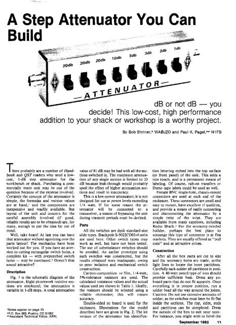
A <strong>Step</strong> <strong>Attenuator</strong> <strong>You</strong> <strong>Can</strong><br />
dB or not dB -<br />
decide! This low-cost, high performaice<br />
addition to your shack or workshop is a worthy project.<br />
T here probably are a number of Handbook<br />
and QST readers who need a lowcost.<br />
I-dB step attenuator for the<br />
workbench or shack. Purchasing a commercially<br />
made unit may he out of the<br />
question because of the expense involved.<br />
Certainly the concept of the attenuator is<br />
simple, the formulas and resistor values<br />
are at hand.' and the components are<br />
inexpensive and readily available. But<br />
layout of the unit and concern for the<br />
careful assembly involved (if good,<br />
reliable results are to be obtained) are, for<br />
many. enough to put the idea far out of<br />
mind.<br />
Well, take heart! At last you can have<br />
that attenuator without agonizing over the<br />
parts layout! The mechanics have been<br />
worked out for you. If you have an aversion<br />
to cutting rectangular switch holes, a<br />
complete kit - with prepunched switch<br />
holes - may he purchased.VI)oesn't that<br />
sound attractive?<br />
Description<br />
Fig. 1 is the schematic diagram of the<br />
attenuator. Eight pi-network resistive sec-<br />
tions are employed; the attenuation is<br />
variable in l-dB stem. A total attenuation<br />
'Notes appear on page 13.<br />
.P.O. Box 968, Pueblo. CO 81002<br />
*'Assistant Technical Editor, ARRL<br />
value of 81 dB may be had with all the sec-<br />
tions switched in. The maximum attenua-<br />
tion of any single section is limited to 20<br />
dB because leak-through would probably<br />
spoil the effect of higher attenuation sec-<br />
tions and result in inaccuracy.<br />
This is a low-power attenuator; it is not<br />
designed for use at power levels exceeding<br />
I/4 watt. If for some reason the at-<br />
tenuator will be connected to a<br />
transceiver, a means of bypassing the unit<br />
during transmit periods must be devised.<br />
Patts<br />
All the switches are dpdt standard-size<br />
slide types. Stackpole S-5022CD03-0 units<br />
are used here. Other switch types may<br />
work as well, but have not been tested.<br />
The use of subminiature switches should<br />
be avoided. An earlier prototype using<br />
such switches was constructed, but the<br />
results obtained were inadequate, owing<br />
to poor isolation and mechanical switch<br />
construction.<br />
Carbon-composition or film. 114-watt,<br />
5%-tolerance resistors are ~ used. The<br />
calculated resistance values and the actual<br />
values used are shown in Table 1. Ideally,<br />
the resistors should be selected using a<br />
reliable ohmmeter; this will ensure<br />
accuracy.<br />
Double-sided pc board is used for the<br />
enclosure. Dimensions for the model<br />
described hereare given in Fig. 2. The kit<br />
version of the attenuator has identifica-<br />
By Bob Shriner,* WAOUZO and Paul K. Pagel,** NlFB<br />
tion lettering etched into the top surface<br />
(or front panel) of the unit. 'This adds a<br />
nice touch, and is a permanent means of<br />
labeling. Of course, rub-on transfers or<br />
Dymo tape labels could be used a? well.<br />
Frtnale BNC single-hole, chassis-mount<br />
connectors are used at each end of the<br />
enclosure. These connectors are small and<br />
easy to mount, have excellent rf qualities,<br />
and provide a means of easily cumecting<br />
and disconnecting the attenuator by a<br />
simple twist of the wrist. They are<br />
available from many suppliers, including<br />
Radio Shack.' For the economy-minded<br />
huilder, perhaps the best place to<br />
scrounge this type of connector is at flea<br />
markets. They are usually offered as "pull<br />
outs" and at attractive prices.<br />
construction<br />
After all the box parts are cut to size<br />
and the necessary holes are made, scribe<br />
light lines to locate the inner partitions.<br />
Carefully tack-solder all partitions in posi-<br />
tion. A 40-watt pencil type of iron should<br />
provide sufficient heat. Dress any pc-<br />
board parts that do not fit squarely. Once<br />
everything is in proper position, run a<br />
solder bead all the way around the joints.<br />
Caution: Do not use excessive amounts of<br />
solder, as the switches must later be fit flat<br />
inside the sections. The top, sides, ends<br />
and partitions can be completed. Dress<br />
the outside of the box to suit your taste.<br />
For instance, you might wish to bevel the<br />
September 1882 11
Fig. 1 - Schematic diagram of the attenuator. Resistors are 114.W, 5%-tolerance, carboncomposition or film types. Resistances am given in ohms.<br />
Table 1<br />
PI Network Attenustor Rerlrtance Values<br />
for 62 Ohm Impedance<br />
Calculated Value Standard Value Used<br />
dB R1, R3 R2 Rl. R3 R2<br />
1 904 8 910 6.2<br />
2 453 12 470 12<br />
1: ~ ~. -<br />
r-<br />
...<br />
TOP ,."-i~<br />
y- .- 3 - an,.<br />
",<br />
SlDEL<br />
i l REQUIRED) 1<br />
- Fig. 2 -- Mechantcal dimensions of the attenuator enclosure.<br />
box edges. Buff the copper with steel<br />
wool, add lettering, and finish off the<br />
work with a coat of clear lacquer or<br />
polyurethane varnish.<br />
Using a little lacquer thinner or acetone<br />
(and a lot of caution), soak the switches to<br />
remove the grease that was put in during<br />
their manufacture. When dry, spray the<br />
inside of the switches lightly with a TV-<br />
tuner cleaner/lubricant. IJsing a sharp<br />
drill bit (about 3/16 inch will do).'<br />
countersink the mounting holes on the ac-<br />
tuator side of the switch mounting plate.<br />
This ensures that the switches will fit flush<br />
against the top plate. At one end of each<br />
switch, bend the two lugs over and solder<br />
them together. Cut off the upper halves of<br />
the remaining switch lugs. (A look at Fig.<br />
3 will help clarify these steps.)<br />
Solder the horizontal members of the pi<br />
12 UST.<br />
sections between the appropriate switch<br />
lugs. Try to keep the lead lengths as short<br />
as possible, and do not overheat the<br />
resistors. Now solder the switches in place<br />
to the top section of the enclosure by<br />
tlowing solder through the mounting<br />
holes and onto the circuit-board material.<br />
Be certain that you place the switches in<br />
their proper positions; correlate the<br />
resistor values with the degree of attenua-<br />
tion. Otherwise, you may wind up with<br />
the l-dB step at the wrong end of the box<br />
- how embarrassing!<br />
Once the switches are installed, thread a<br />
piece of no. 18 bare copper wire through<br />
the center lugs of aU the switches. passing<br />
it through the holes in the partitions.<br />
Solder the wire at each switch terminal.<br />
Cut the wire between the poles of each in-<br />
dividual switch, leaving the wire con- 'ig. 3 - Ciose.up of the switch detail
Fig. 4 - An Inside view of the completed attenuator. Use of short, direct leads enhances the performance of the unit. Brass nuts soldered at each of<br />
the four corners allow machine screws to be used to secure the bottom cover. File one corner of each nut to permit a flat, two-sided fit wlthln the<br />
enclosure.<br />
necting one switch pole to that of the<br />
neighboring one on the other side of the<br />
partition, as shown in Fig. 4.<br />
At each of the two end switch ter-<br />
minals. leave a wire length of ap-<br />
proximately 1/8 inch. Install the BNC<br />
connectors, and solder the wire pieceti to<br />
the connector center conductors.<br />
Now install the resistors that comprise<br />
the vertical (grounded) legs of each pi sec-<br />
tion. Use short lead lengths. Remember<br />
that physical symmetry is conducive to<br />
good performance. Do not use excessive<br />
amounts of heat when soldering.<br />
Solder a no. 4-40 brass nut at each in-<br />
side corner of the enclosure. Recess the<br />
nuts approximately 1/16 inch from the<br />
bottom edge of the box to allow sufficient<br />
room for the bottom panel to fit flush.<br />
Secure the bottom panel with four no.<br />
4-40, l/4-inch machine screws and you're<br />
done!<br />
The End Result<br />
ARRL lab tests proved the attenuator<br />
to be a good performer. A Hewlett-<br />
Packard R640B signal generator and a<br />
85548 spectrum analyzer were used with a<br />
Tektronix 2701 step attenuator in the test<br />
setup. Results of the insertion-loss<br />
measurements, with no attenuation<br />
switched in, are shown in Table 2. The<br />
Table 2<br />
<strong>Attenuator</strong> Insertion Loss<br />
Frequency (MHz) 29.7 50 144 220 450<br />
Insertion loss (dB)