LED-Flatlight-Spot d60 - Henning GmbH
LED-Flatlight-Spot d60 - Henning GmbH
LED-Flatlight-Spot d60 - Henning GmbH

Create successful ePaper yourself
Turn your PDF publications into a flip-book with our unique Google optimized e-Paper software.
Elevator components<br />
MASTER CATALOGuE<br />
RIDE<br />
<strong>LED</strong><br />
1
2<br />
table of contents<br />
Load measuring technology<br />
Acceleration measuring technology<br />
Damping technology<br />
Illumination technology<br />
Cabin equipment<br />
table of contents<br />
Produktbereich Kapitel Kapitelkatego<br />
Chapter Category<br />
1 1.0<br />
1.1<br />
1.2<br />
1.3<br />
2 2.0<br />
2.1<br />
3 3.0<br />
3.1<br />
4 4.0<br />
4.1<br />
4.2<br />
4.3<br />
4.4<br />
5 5.0<br />
5.1<br />
5.2<br />
5.3<br />
5.4<br />
5.5<br />
5.6
ie<br />
Product Page<br />
WEIGHTWATCHER Over-load control system 7 - 11<br />
WEIGHTWATCHER LIGHT Over-load control system 12 - 14<br />
WEIGHTWATCHER LIGHT MultiRope Over-load control system 15 - 16<br />
MOBILE WEIGHTWATCHER rope load measuring system 17 - 23<br />
LiftPC® mobile Diagnosis 26 - 28<br />
Ride Watcher 29<br />
Lift buffer 32 - 34<br />
door closer 35 - 45<br />
<strong>LED</strong> <strong>Spot</strong> / power unit 50 - 57<br />
<strong>LED</strong> Panel 58 - 62<br />
Landing Lighting 63 - 67<br />
Shaft Illumination 68<br />
LightWatcher 69<br />
Landing Indicator 72 - 74<br />
Emergency Lift Telephone 75 - 80<br />
Assembly tools 81 - 84<br />
False car 85<br />
Handrail for the cabin roof 86 - 87<br />
Car Apron 88<br />
ROPE GRIPPER TM 89<br />
1<br />
2<br />
3<br />
4<br />
5<br />
3
LOAD MEASuRInG TECHnOLOGy<br />
1<br />
5
Weight Watcher Weight Watcher light Weight Watcher light MultiRope<br />
Evaluation unit AE12 AE16 light AE8 light MultiRope, sensor is connected to the<br />
evaluation unit<br />
WEIGHTWATCHER OVER-LOAD COnTROL SySTEM 1.0<br />
Comparison of WeightWatcher, WeightWatcher light and WeightWatcher light MultiRope<br />
number Of Sensors 12 16 8 1<br />
Voltage 12 - 28 VDC 12 - 28 VDC 12 - 28 VDC 12 - 28 VDC<br />
Power Consumption 4 W 0,8 W 0,8 W 1 W at 12 V DC<br />
Output Relays 4 nO/nC (zero load, full load, overload, slack rope) 3 CO, freely programmable 2 CO, freely programmable 2 Wechsler, freely programmable<br />
Analogue Output optional optional l l<br />
Hold Input 12 - 230 VAC/DC 12 - 230 VAC/DC l 12 - 230 VAC/DC<br />
CanOpen optional optional l l<br />
Display <strong>LED</strong>, 4 digits <strong>LED</strong>, 5 digits <strong>LED</strong>, 5 digits <strong>LED</strong>, 4 digits<br />
Operation 3 keys 3 keys 3 keys 3 keys<br />
Determination Of Car Weight l l l l<br />
Rope Tension Assistant l (Via Laptop) l l l<br />
Configuration by laptop l (uSB-Kabel) l (special cable) l l<br />
Dimensions (L x W x H) 105 x 90 x 62 mm 115 x 80 x 40 mm 115 x 80 x 40 mm sensor is connected to the evaluation<br />
unit<br />
Art.-no. 455000, 455002 (Analog), 455005 (CanOpen) 456000 456100<br />
Rope Load Sensors LS 1 LS2 LS 2000 LS light MultiRope 200 MultiRope 300<br />
Art.-no. 455500 455400 455850 456500 456600 456700<br />
Rope Diameter 6 - 16 mm 4 - 10 mm 6 - 16 mm 4 - 13 mm 4 - 26 mm 4 - 26 mm<br />
Measuring Range 0 - 500 kg 0 - 300 kg 100 - 2000 kg 0 - 500 kg 300 - 2500 kg 700 - 6000 kg<br />
optional 10.000 kg<br />
Measuring Principle Strain Gauge Strain Gauge Strain Gauge Strain Gauge Strain Gauge<br />
Calibrated Sensors l l pre-cal../rope Ø weight l l l<br />
Calibration After Installation l l l l l l<br />
Temperature Range 0° - 70°C 0° - 70°C 0° - 70°C 0° - 70°C 0° - 70°C 0° - 70°C<br />
Length Of Cable 2,5 m 2,5 m 2,5 m 2,5 m 5 m 5 m<br />
Dimensons (L x W x H) 250 x 80 x 18 mm 178 x 72 x 17 mm 300 x 80 x 80 mm 110 x 70 x 22 mm 220 x 220 x 132 mm 220 x 320 x 142 mm<br />
l = Standard<br />
l = not available<br />
1<br />
7
1<br />
8<br />
1.0 WEIGHTWATCHER OVER-LOAD COnTROL SySTEM<br />
WEIGHTWATCHER OVER-LOAD COnTROL SySTEM<br />
The <strong>Henning</strong> over-load control system is based on a patented measuring principle. Every rope is provided with a rope sensor which no longer needs to be calibrated using<br />
weights; the time-consuming installation of weights is no longer necessary. Storekeeping, too, is simplified: one sensor module matches up to 11 different rope diameters.<br />
The rope tension setting assistant integrated in the software is unique and amazingly simple: it only takes a few minutes to achieve an optimum setting of a complete set of<br />
ropes. This and the permanent rope tension monitoring feature allow the undesired and needless wear of traction sheaves and ropes to be prevented in a reliable manner.<br />
Highlights of the WeightWatcher<br />
over-load control system:<br />
• Calibration with weights not necessary thanks to the patented<br />
measuring principle<br />
• Suitable for different rope diameters and rope types<br />
• 4 programmable alarm relays<br />
• Up to 12 rope sensors per evaluation unit<br />
• Integrated slack rope alarm<br />
• Permanent monitoring of the load distribution<br />
• Equipped with USB interface and free PC software<br />
• Software wizard for the adjustment of the optimum<br />
single rope tension to avoid unnecessary wear<br />
Operation of the WeightWatcher system:<br />
Every single rope is fitted with a load sensor. After having put he sensor against the<br />
rope, it is attached by tightening up only one hexagon socket screw. The flattened<br />
spring washer indicates to the fitter that the proper tightening torque has been applied.<br />
The sensors are simply plugged into the evaluation unit AE 12 which – without any calibration<br />
by weights – immediately indicates the overall weight and the individual rope<br />
loads. The desired alarms are set via the display and keys of the unit or via the free PC<br />
software. The unit then triggers the alarms for up to 4 different load limits, slack rope<br />
conditions and any diverging individual rope loads.<br />
Installed and ready for operation within minutes!
WEIGHTWATCHER OVER-LOAD COnTROL SySTEM 1.0<br />
Evaluation unit AE 12<br />
In addition to 12 independent measuring channels, Evaluation Unit AE12 offers<br />
3 alarm relays for freely programmable loads as well as an additional alarm relay<br />
for slack-rope montoring and load distribution monitoring.<br />
It can be programmed either by means of its <strong>LED</strong>-display and three keys or via USBinterface<br />
and the free software WeightWatcher. Rope load sensors LS1 or LS2 are to<br />
be ordered separately according to your individual needs.<br />
Technical Data:<br />
Power supply voltage 12 V – 28 V DC<br />
Power consumption max. 4 W<br />
Number of relay outputs 4<br />
max. switching voltage 250 V AC<br />
max. starting current 15 A<br />
max. constant current 10 A<br />
max. switching power (ohmic load) 2500 W<br />
max. switching power (ind. load) 500 VA<br />
min. switching power 0.3 W<br />
Numbers of measuring channels 12<br />
Range 30 Hz<br />
Sampling frequency 100 Hz<br />
HOLD input 12 V - 230 V AC/DC<br />
CANopen (optional) DSP 417<br />
Type Article-no.<br />
Evaluation unit AE 12 455000<br />
Evaluation unit AE 12 wit analogue output 455002<br />
Evaluation unit AE 12 CANopen 455005<br />
1<br />
9
1<br />
10<br />
1.0 WEIGHTWATCHER OVER-LOAD COnTROL SySTEM<br />
Rope load sensor LS1<br />
(6 - 16 mm / 1/4 - 5/8 inch)<br />
Design of the rope load sensor LS1 follows a patented measuring principle ceasing<br />
the expensive calibration of the elevator by test weights. The rope load sensor suits<br />
rope diameters from 6 mm (1/4 inch) to 16 mm (5/8 inch) and is ready for use. It is<br />
provided with a mains lead of 2,5 m length.<br />
Technical Data:<br />
Rope diameter 6 mm - 16 mm / 1/4 inch - 5/8 inch<br />
Measuring range 0 - 500 kg (± 2,5%)<br />
Maximum load 1000 kg<br />
Breaking load 2000 kg<br />
L x W x H (mm) 250 x 75 x 19<br />
Connection cable length 2,5 m<br />
Temperature range 0 °C - 70 °C<br />
Type Article-no.<br />
Rope load sensor LS1 (6 - 16mm / 1/4 - 5/8 inch) 455500<br />
LS connection cable extension up to 20 m 455505<br />
Rope load sensor LS2<br />
(4 - 10 mm / 3/16 - 3/8 inch)<br />
Design of the rope load sensor LS2 follows a patented measuring principle ceasing<br />
the expensive calibration of the elevator by test weights. The rope load sensor suits<br />
rope diameters from 4 mm (3/16 inch) to 10 mm (3/8 inch) and is ready for use. It is<br />
provided with a mains lead of 2,5 m length.<br />
Technical Data:<br />
Rope diameter 4 mm - 10 mm / 3/16 inch - 3/8 inch<br />
Measuring range 0 - 300 kg<br />
Maximum load 600 kg<br />
Breaking load 1200 kg<br />
L x W x H (mm) 178 x 58 x 16<br />
Connection cable length 2,5 m<br />
Temperature range 0 °C - 70 °C<br />
Type Article-no.<br />
Rope load sensor LS2 (4 - 10 mm / 3/16 - 3/8 inch) 455400<br />
LS connection cable extension up to 20 m 455505
LS 2000<br />
WEIGHTWATCHER OVER-LOAD COnTROL SySTEM 1.0<br />
Rope load sensor LS 2000<br />
(6 - 16 mm / / 1/4 - 5/8 inch)<br />
Rope load sensor for special use with extended measuring range.<br />
Inclusive Pre-calibrated for rope diameters - and Measuring ranges.<br />
Technical Data:<br />
Rope diameter 6 mm - 16 mm<br />
Measuring range 100 - 2000 kg<br />
Maximum load 4000 kg<br />
Breaking load 6000 kg<br />
L x B x H (mm) 300 x 80 x 80<br />
Connection cable length 2,5 m<br />
Temperature range 0 °C - 70 °C<br />
Type Article-no.<br />
Rope load sensor LS 2000 (6 -16 mm / 1/4 - 5/8 inch) 455850<br />
LS connection cable extension up to 20 m 455505<br />
AE12 Software<br />
By this software, the parameters of evaluation unit AE12 can be set and the unit configurated.<br />
Furthermore, it provides the comfortable rope-adjusting assistant enabling<br />
you to adjust a rope set within a few minutes.<br />
Free download from www.henning-gmbh.de<br />
1<br />
11
1<br />
12<br />
1.1 WEIGHTWATCHER LIGHT OVER-LOAD COnTROL SySTEM<br />
WEIGHTWATCHER LIGHT OVER-LOAD COnTROL SySTEM<br />
During the development of the WeightWatcher Light series our development division could rely on the knowhow acquired over many years. Great store was set by the ease<br />
of installation and the request put forward by many customers to provide a reasonably priced but high-quality overload measuring system which meets the requirements of<br />
EN 81. The load measuring sensors LS-Light round off the existing product line of <strong>Henning</strong> load measuring systems in the reasonably priced segment and are suitable for<br />
almost all fitting situations. Thanks to its small size the LS sensor even fits where shaft ceilings are low and ropes are closely spaced. The applications in the range of 4 to 13<br />
mm rope diameters also meet requirements. Up to 16 sensors can be connected to the evaluation unit Light using the 2.5 m long cables.<br />
Highlights of the WeightWatcher Light<br />
over-load control system:<br />
• Extremely attractive value for money option<br />
• Ease of installation<br />
• One type of sensor for rope diameters ranging from 4 to 13 mm<br />
• Extremely compact rope load sensors<br />
• 3 freely programmable output relays<br />
• Measurements possible on up to 8 or 16 ropes<br />
Operation of WeightWatcher Light:<br />
During installation the pin of the retaining strap is opened and the sensor is put against<br />
the rope. The retaining strap is then closed again and the clamping screw is tightened<br />
up until the rope is pressed against the sensor body. An exact tightening torque must<br />
not be applied. Special tools are not needed.<br />
The LS-Light rope load sensors are connected to the evaluation units AE 8 Light or<br />
AE16 Light. The installation with plugs (no terminals) saves time and prevents mistakes<br />
being made during connection. After the rope load sensors LS-Light are calibrated,<br />
the evaluation unit Light displays the load of the lift car. A connection to the control<br />
system is effected using 3 freely programmable alarm relays, one optional analogue<br />
output or the CANopen option. As soon as the parameters for the 3 output relays are<br />
entered via the built-in keys, the unit is ready for operation.
WEIGHTWATCHER LIGHT OVER-LOAD COnTROL SySTEM 1.1<br />
Evaluation unit AE16 light<br />
In addition to 16 independent measuring channels, AE16 offers 3 freely programmable<br />
output relays with changeover contacts.<br />
This unit can be programmed by its keys. Rope load sensors LS-light are to be ordered<br />
separately according to your needs.<br />
Technical Data:<br />
Power supply voltage 12 V - 28 V DC<br />
Power consumption < 0,8 W<br />
Number of relay outputs 3<br />
max. switching voltage 250 VAC<br />
Number of measuring channels 16<br />
HOLD input 12 V - 230 V AC/DC<br />
CANopen (optional) DSP 417<br />
Analogue output (optional) 0 - 20 mA<br />
4 - 20 mA<br />
Type Article-no.<br />
Evaluation unit AE16 light 456000<br />
Evaluation unit AE8 light<br />
Up to 8 sensors can be connected by their 2,5-m-cables to the evaluation unit AE8 light.<br />
This is connected to the lift control unit via 2 freely programmable alarm-relays or an<br />
optional analog output.<br />
Under preparation is a CANopen execution of AE8 light. Configuration of the unit is<br />
executed by three buttons and the 5-digit <strong>LED</strong>-indicator. AE8 light is highly energyefficient<br />
with regard to its typical power draw of less than 0,8 W.<br />
Technical Data:<br />
Power supply voltage 12 - 28 VDC<br />
Power consumption max. 0,8 W<br />
Number of relay outputs 2<br />
max. switching voltage 250 VAC<br />
Number of measuring channels 8<br />
Type Article-no.<br />
Evaluation unit AE8 light 456100<br />
1<br />
13
1<br />
14<br />
1.1 WEIGHTWATCHER LIGHT OVER-LOAD COnTROL SySTEM<br />
Rope load sensor LS-light<br />
(4 - 13 mm / 3/16 - 1/2 inch)<br />
Rope load sensors LS-light are made for low lift shaft heads and narrow-layed ropes<br />
and suit rope diameters of 4 to 13 mm (3/16 - 1/2 inch). They suit almost every low<br />
and narrow siting.<br />
Technical Data:<br />
Rope diameter 4 - 13 mm / 3/16 - 1/2 inch<br />
Measuring range 0 - 500 kg<br />
Maximum load 1000 kg<br />
Breaking load 2000 kg<br />
L x W x H (mm) 110 x 30 x 12<br />
Cable length 2,5 m<br />
Temperature range 0°C - 70°C<br />
Type Artikel-no.<br />
Rope load sensor LS-light 456500<br />
Casing – For Evaluation units AE12 And AE16<br />
Light,To Be Installed On The Elevator Car.<br />
Equipped with a top-hat rail to bear the evaluation unit and 2 PG-glands<br />
(M20 and M25) for the control and mains lines.<br />
In your order please state the number of rope load sensors to be used.<br />
Technical Data:<br />
Type of protection IP 65<br />
Material Thermoplast<br />
Colour grey RAL 7035,<br />
wall-side for cable lead-in<br />
Cable lead-in max. M 40<br />
Type Article-no.<br />
Casing AE12/AE16/AE8 455020
WEIGHTWATCHER LIGHT MultiRope OVER-LOAD COnTROL SySTEM 1.2<br />
WEIGHTWATCHER LIGHT MultiRope OVER-LOAD<br />
COnTROL SySTEM<br />
For the development of the latest product of the WeightWatcher Light series, the MultiRope measuring system, our development division could rely on the knowhow gathered<br />
over many years.<br />
Great store was set by the ease of installation and the request put forward by many customers to provide a reasonably priced but high-quality overload measuring system which<br />
meets the requirements of EN 81. The applications in the range of 4 to 26 mm rope diameters also meet requirements. Measuring ranges of up to max. 10,000 kg (optional for<br />
MultiRope 300) allow a wide variety of applications. The Multirope 200 and 300 load sensors are particularly easy to handle allowing them to be installed in a wide variety of fitting<br />
situations. Even closely spaced ropes or low shaft ceilings present no problem.<br />
One-for-all<br />
Highlights of WeightWatcher Light<br />
MultiRope:<br />
• Extremely attractive value for money option<br />
• Ease of installation<br />
• Two types of sensor for 200 and 300 mm clamping widths<br />
• For 4 to 26 mm rope diameters<br />
• Measuring range up to 10.000 kg<br />
• 2 freely programmable output relays<br />
• Integrated evaluation unit<br />
Operation of the WeightWatcher Light<br />
MultiRope:<br />
Only a few minutes are needed to install the MultiRope sensors:<br />
The installation only requires the screws of the retaining strap to be loosened and the<br />
sensor to be put against the rope. The retaining strap is then closed again and the<br />
screws are tightened up until the rope is pressed against the sensor body. A specific<br />
tightening torque must not be applied. No special tools are required.<br />
Thanks to the integrated evaluation unit no additional cables are needed to connect the<br />
sensor and evaluation unit. The unit can be configured using three keys and the 4-digit<br />
<strong>LED</strong> display.<br />
The unit is connected to the control system by means of 2 freely programmable alarm<br />
relays.<br />
After the MultiRope sensor has been calibrated, the evaluation unit displays the lift car<br />
load.<br />
As soon as the parameters for the 2 output relays are entered using the built-in keys,<br />
the unit is ready for operation.<br />
1<br />
15
1<br />
16<br />
1.2 WEIGHTWATCHER LIGHT MultiRope OVER-LOAD COnTROL SySTEM<br />
WeightWatcher Light MultiRope<br />
Electrical data:<br />
relays 2 changeover relays<br />
Max. contact voltage 250 V AC/220 V Dc<br />
Max. making current: 30 V DC 1 A<br />
125 V AC 0,3 A<br />
Max. permanent current 30 V DC 1 A<br />
125 V AC 0,3 A<br />
Max. switching capacity (ohmic load) 62 VA<br />
Max. switching capacity (ind. load) 62 VA<br />
Min. contact rating 10 mV DC 0,01 mA<br />
Length cable set 5 m<br />
supply voltage 12 V - 28 V DC<br />
Hold-input 12 V - 230 AC/DC<br />
MultiRope 200<br />
Electrical data:<br />
Clamp width 200 mm<br />
Rope diameter 4 mm - 26 mm<br />
Measuring range 300 kg - 2500 kg<br />
Max. load 5000 kg<br />
Dimensions L x B x H 220 mm x 220 mm x 132 mm<br />
Weight ca. 3,5 kg<br />
MultiRope 300<br />
Electrical data:<br />
Clamp width 300 mm<br />
Rope diameter 4 mm - 26 mm<br />
Measuring range 700 kg - 6000 kg<br />
(optional 10000 kg)<br />
Max. load 12000 kg<br />
Dimensions L x B x H 220 mm x 320 mm x 142 mm<br />
Weight: ca. 8,0 kg<br />
Type Article-no.<br />
MultiRope 200 456600<br />
MultiRope 300 456700
MOBILE WEIGHTWATCHER ROPE LOAD MEASuRInG SySTEM 1.3<br />
MOBILE WEIGHTWATCHER ROPE LOAD<br />
MEASuRInG SySTEM<br />
Inadequately set ropes and excessive overall weights cause an undesired and premature wear. The WeightWatcher rope load measuring system allows ropes to be set and lift<br />
car and counterweight loads to be weighed in no time at all.<br />
The LSM-Belt sensor especially developed for belts allows measurements to be carried out on 30 to 60 mm wide belts.<br />
The integrated rope setting assistant guides you through the rope setting procedure and records every measurement with a report that can later be printed out on the PC.<br />
This makes the mobile WeightWatcher an optimum tool for your service work. Apart from weighing the lift car and counterweight loads, all single rope loads can be displayed and<br />
adjusted within a few minutes to their optimum settings using the integrated rope setting assistant.<br />
Highligts of the mobile WeightWatcher:<br />
• Time-saving adjustment of rope tensions<br />
• Quick measurement of lift car and counterweight loads<br />
• LSM rope load sensors with quick-action clamping facility<br />
• Integrated software assistant for an ideal setting of single<br />
rope tensions<br />
• For different rope diameters and rope types dia. 4-10 mm, dia. 6-16<br />
or dia. 16-24 mm as well as for belts<br />
• No calibration with weights necessary<br />
• 12 measuring channels for up to 12 ropes<br />
• Stores up to 100 measurements<br />
• Report can be printed out via the supplied PC software<br />
Operation of the mobile WeightWatcher:<br />
Every rope is fitted with a load sensor. After the sensor is put against the rope only a<br />
clamping lever has to be shifted.<br />
Up to 12 sensors are simply plugged into the evaluation unit MSM12 which – without<br />
any calibration with weights – immediately displays the overall weight and the individual<br />
rope loads.<br />
A uniform rope setting is now extremely easy: within a few minutes an integrated rope<br />
load assistant guides you through the single rope adjustment steps which the software<br />
has already calculated in advance.<br />
The rope load assistant specifies a setting for each single rope.<br />
The rope setting can be stored in the unit for documentation purposes.<br />
This allows the ropes to be set in a comfortable manner even with complicated suspension<br />
modes and a high number of ropes and no longer costs a lot of time.<br />
It is also possible to store as much as 100 rope load measurements in the internal memory<br />
of the MSM12 which can later be transferred to a database using the free software<br />
for quality assurance purposes or be archived as a printed document.<br />
1<br />
17
1<br />
18<br />
1.3 MOBILE WEIGHTWATCHER ROPE LOAD MEASuRInG SySTEM<br />
Kit: Mobile Evaluation unit MSM12 + 4 LSM1<br />
Kit comprises:<br />
• Mobile evaluation unit (Art. No. 455101)<br />
• 4 sensors LSM1 (Art. No. 455600)<br />
• USB connecting cable<br />
• 4 AA cells<br />
The kit is supplied in a rigid aluminium case offering space for up to 10 rope<br />
load sensors LSM1 or LSM2.<br />
Rope load sensors of the types LSM1, LSM2, LSM-XL or LSM-Belt can be ordered<br />
in addition.<br />
Type Article-no.<br />
Kit: Mobile Evaluation Unit MSM12 + 4 LSM1 455100<br />
Bluetooth extension class 2 455110<br />
Kit: Mobile Evaluation unit MSM12 + 4 LSM2<br />
Kit comprises:<br />
• Mobile evaluation unit (Art. No. 455101)<br />
• 4 sensors LSM2 (Art. No. 455700)<br />
• USB connecting cable<br />
• 4 AA cells<br />
The kit is supplied in a rigid aluminium case offering space for up to 10 rope<br />
load sensors LSM1 or LSM2.<br />
Rope load sensors of the types LSM1, LSM2, LSM-XL or LSM-Belt can be ordered<br />
in addition.<br />
Type Article-no.<br />
Kit: Mobile Evaluation Unit MSM12 + 4 LSM2 455200<br />
Bluetooth extension class 2 455110
MOBILE WEIGHTWATCHER ROPE LOAD MEASuRInG SySTEM 1.3<br />
Kit: Mobile Evaluation unit MSM12 + 4 LSM-XL<br />
Kit comprises:<br />
• Mobile evaluation unit (Art. No. 45000375)<br />
• 4 sensors LSM-XL (Art. No. 455310)<br />
• USB connecting cable<br />
• 4 AA cells<br />
Special case for transport of up to 6 LSM-XL available<br />
under Art. No. 455310. Not included in Kit.<br />
Further sensors LSM1, LSM2, LSM-XL oder LSM-Belt can be extra ordered<br />
Type Article-no<br />
Kit: Mobile Evaluation Unit MSM12 + 4 LSM-XL 455300<br />
Transport Case With Rollers 455310<br />
Bluetooth extension class 2 455110<br />
Kit: Mobile Evaluation unit MSM 12 + 3 LSM-Belt<br />
for 30 mm + 60 mm belts<br />
Kit comprises:<br />
• Mobile evaluation uni (Art.-Nr.: 455101)<br />
• 3 sensors LSM-Belt (Art.-Nr.: 455800)<br />
• USB-connecting cable<br />
• 4 AA cells<br />
Delivered with aluminium case.<br />
Special case for transport of up to 4 sensors LSM-Belt.<br />
Further sensors LSM1, LSM2, LSM-XL oder LSM-Belt can be extra ordered<br />
Type Article-no.<br />
Kit: Mobile Evaluation UnitMSM 12 + 3 LSM-Belt 455810<br />
Bluetooth extension class 2 455110<br />
1<br />
19
1<br />
20<br />
1.3 MOBILE WEIGHTWATCHER ROPE LOAD MEASuRInG SySTEM<br />
Mobile Evaluation unit MSM12<br />
MSM12 is operated by means of a big lit graphic-touch display.<br />
Up to 100 measurements can be stored in the integrated protocol memory andread out<br />
via USB-interface onto the PC.<br />
MSM12 is connectable for up to 12 rope load sensors LSM1, LSM2, LSM-XL or<br />
LSM-belt.<br />
It is supplied with voltage by 4 AA-cells or 4 rechargeable cells (not included in the<br />
range of supply).<br />
Technical Data<br />
Power Supply 4 round-cells LR6, AA<br />
Number of measuring channels 12<br />
Range 3 0 Hz<br />
Sampling frequency 100 Hz<br />
L x W x H (mm) 190 x 138 x 46<br />
Interface USB 2.0,<br />
Bluetooth Class 2 (optional)<br />
Bluetooth Extension Class 2<br />
Bluetooth Class 2, En 300 328 complian<br />
Bluetooth interface extension for the mobile evaluation unit MSM12, including an external<br />
antenna for wirelessly transferring rope load measurement data to a computer.<br />
The PC-software “MSM12 extended” is included. Over the course of time, it facilitates<br />
logging, printing, outreading and storing the load behaviour for each single rope.<br />
This article is to be supplied only in connection with the mobile evaluation unit<br />
MSM12. To operate MSM12 via a bluetooth connection, you will require a computer<br />
with a bluetooth interface.<br />
To be ordered together with MSM12, not separately. Can be retrofitted in our<br />
factory only.<br />
Type Article-no.<br />
Mobile Evaluation Unit MSM12 455101<br />
Bluetooth extension class 2 455110<br />
Mobile Rope Load Sensor LSM1<br />
(6 - 16 mm / 1/4 - 5/8 inch)<br />
LSM1 is designed according to a patented measuring principle that does no longer<br />
require any expensive elevator calibration by testing weights.<br />
This rope load sensor suits rope diameters from 6 mm to 16 mm and can be applied<br />
straightaway.<br />
Its excentric lever allows the sensor to be fitted to the rope within a few seconds.<br />
LSM1 is equipped with a mains cable of 0,8 m length.<br />
Technical Data<br />
Rope diameter 6 mm - 16 mm / 1/4 inch - 5/8 inch<br />
Measuring range 0 - 500 kg (+ 2,5%)<br />
Maximum load 1000 kg<br />
Breaking load 2000 kg<br />
L x W x H (mm) 250 x 75 x 19<br />
Cable length 0,8 m<br />
Temperature range 0 °C - 70 °C<br />
Type Article-no.<br />
Mobile Rope Load Sensor LSM1 (6 - 16 mm / 1/4 - 5/8 inch) 455600<br />
LSM connection cable extension up to 20 m 455620
MOBILE WEIGHTWATCHER ROPE LOAD MEASuRInG SySTEM 1.3<br />
Mobiler Seilsensor LSM2 (4 - 10 mm)<br />
LSM2 is designed according to a patented measuring principle that does no longer<br />
require any expensive elevator calibration by testing weights.<br />
This rope load sensor suits rope diameters from 4 mm (3/16 inch) to 10 mm (3/8 inch)<br />
and can be applied straightaway. Its excentric lever allows the sensor to be fitted to<br />
the rope within a few seconds.<br />
LSM2 is equipped with a mains cable of 0,8 m length.<br />
Technical Data<br />
Rope diameter 4 mm - 10 mm / 3/16 inch - 3/8 inch<br />
Measuring range 0 - 300 kg (+ 2,5%)<br />
Maximum load 600 kg<br />
Breaking load 1200 kg<br />
L x W x H (mm) 178 x 58 x 16<br />
Cable length 0,8 m / 31,5 inch<br />
Temperature range 0 °C - 70 °C<br />
Type Article-no.<br />
Mobile Rope Load Sensor LSM2 (4 - 10 mm / 3/16 - 3/8 inch) 455700<br />
LSM connection cable extension up to 20 m 455620<br />
Mobile Rope Load Sensor LSM-XL<br />
(16 - 24 mm / 5/8 - 15/16 inch)<br />
LSM-XL is designed according to a patented measuring principle that does no longer<br />
require the expensive elevator calibration by testing weights. This rope load sensor<br />
suits rope diameters from 16 mm (5/8 inch) to 24 mm (15/16 inch) and can be applied<br />
straightaway. Its excentric lever allows the sensor to be fitted to the rope within a few<br />
seconds.<br />
It is equipped with a mains cable of 1,5 m length.<br />
For transportation we recommend transport case No. 455310 suitable for up to<br />
6 rope load sensors.<br />
Technical data:<br />
Rope diameter 16 mm - 24 mm / 5/8 inch - 15/16 inch<br />
Measuring range 200 - 2000 kg (+ 3,5%)<br />
Maximum load 4000 kg<br />
Breaking load 6000 kg<br />
L x B x H (mm) 570 x 210 x 50<br />
Cable length 1,5 m / 59,06 inch<br />
Temperature range 0 °C - 70 °C<br />
Type Article-no.<br />
Mobile Rope Load Sensor LSM-XL (16 - 24 mm / 5/8 - 15/16<br />
Inch)<br />
455350<br />
LSM connection cable extension up to 20 m 455620<br />
1<br />
21
1<br />
22<br />
1.3 MOBILE WEIGHTWATCHER ROPE LOAD MEASuRInG SySTEM<br />
Mobile Belt Load Sensor LSM-Belt<br />
Special load sensor for belts.<br />
LSM-Belt is designed according to a patented measuring principle that does no<br />
longer require any expensive elevator calibration by testing weights.<br />
This belt sensor suits belts from 30 mm to 60 mm of width and can be applied<br />
straightaway. Its excentric lever allows the belt sensor to be fitted to the belt within<br />
a few seconds.<br />
It is equipped with a mains cable of 0,8 m length.<br />
Technical Data:<br />
Width of belt 30 mm + 60 mm<br />
Measuring range 0 - 500 kg (+ 2,5%)<br />
Maximum load 1000 kg<br />
Breaking load 2000 kg<br />
L x W x H (mm) 230 x 120 x 82<br />
Cable length 0,8 m<br />
Temperature range 0 °C - 70 °C<br />
Type Article-no.<br />
Mobile Belt Load Sensor LSM-Belt 455800<br />
LSM connection cable extension up to 20 m 455620<br />
Protective Bag For MSM12<br />
Features of the bag:<br />
• Material: Cordura, padded, colour black, protection against dust, splashing<br />
water and slight impacts<br />
• Carrying strap<br />
• Operating elements and connection sockets (incl. bluetooth) accessible<br />
without having to open the bag<br />
• Big transparent viewing panel in the bag<br />
Type Article-no.<br />
Protective Bag For MSM12 455099
MOBILE WEIGHTWATCHER ROPE LOAD MEASuRInG SySTEM 1.3<br />
LayOut-Adaptation MSM12<br />
Don’t like our standard layout?<br />
Want to edit reports with your own distinctive layout, using your company logo and<br />
own tests?<br />
Basing on your layout template (Microsoft Word, Acrobat PDF, standard picture files)<br />
we will outline your individual readout report on rope load measuring and adjusting.<br />
Your individual layout is integrated in the existing software by a few mouse-clicks and<br />
can - like the standard report - be edited on different media at your choice (printer, pdffile,<br />
picture file, etc.). Should your layout - for any technical reason - not be feasible, we<br />
will inform you as soon as possible. And no cost will arise.<br />
Free download at www.<strong>Henning</strong>-gmbh.de<br />
1<br />
23
ACCELERATIOn MEASuRInG TECHnOLOGy<br />
2<br />
25
2<br />
26<br />
2.0 Lift PC ® MOBILE DIAGNOSIS<br />
MOBILE RIDE AnALyzER FOR THE ELEVATOR ACCORDInG TO ISO 18738 AnD<br />
GB /T10058-1997<br />
LiftPC Mobile Diagnosis is a powerful measuring system of modular design, serving for mobile and flexible measurements of acceleration and ride quality of elevators. It is<br />
applicable with any laptop or with our Handheld Terminal HT1 in connection with 3D Acceleration Sensor QS 2.0. Data of acceleration and ride quality of the elevator can precisely<br />
be assessed in terms of the standards ISO 18738 and GB/T 10058-1997. LiftPC Mobile Diagnosis can be applied with rope-traction elevators as well as with hydraulically<br />
operated elevators.<br />
Range Of Application<br />
• Documentation of the quality supplied by pre-post comparison<br />
• Service and maintenance of the status quo<br />
• Specific reaction to arising malfunctions<br />
• Preparation of putting into operation and acceptance tests by the authorities<br />
Measuring Characteristics<br />
• Acceleration and deceleration behaviour in all 3 axis<br />
• Stubbing and joggling of the car and at the guide rails<br />
• Recognizing door movements<br />
Evaluation Characteristics<br />
• Documentation of all important data concerning travel acceleration and ride<br />
• Hints to irregularities with doors, guide rails and driving speed control<br />
• Provides exact information of where the malfunction is to be spotted<br />
Design Characteristics<br />
• 3D acceleration sensor for online measuring in all 3 axis<br />
• Pre-calibrated in our factory<br />
• On-the-spot evaluation of the data measured by guided software<br />
• Usage of common evaluation procedures such as filtering attenuation, peaktopeak<br />
evaluation as well as frequency analysis up to 1000 cycles per second,<br />
sampling rate up to 2000 cycles per second<br />
• Suitable for all kinds of elevators<br />
• System-integrated monitoring of the measuring instruments<br />
Characteristics Of 3D-Acceleration Sensor QS 2<br />
Impact resistant up to 20.000 g<br />
Range of ambient temperatures from - 20 °C to + 60 °C<br />
Interfaces to USB 1.1 and Bluetooth<br />
Module / Handheld terminal HT 1.0<br />
Accuracy +/- 1,7 g measuring range per axis<br />
Special feature electronic self-check function<br />
Range Of Supply<br />
• Acceleration Sensor (QS 2.0) with USB 1.1 connector<br />
• Connecting cable for Sensor – Laptop connection<br />
• Transport case with base plate<br />
• Software for data acquisition,<br />
• Data analysis and storage of diagnosis on CD<br />
• User manual<br />
• Noise module class 2<br />
• Magnetic foot with M6 thread<br />
Type Article-no.<br />
LiftPC mobile Diagnosis 450005
Lift PC ® MOBILE DIAGNOSIS 2.0<br />
noise Level Measuring Module Class 2<br />
Extension unit for measuring noises and<br />
assessing them according to ISO 18738<br />
Features<br />
• Noise measuring and assessing according to ISO 18738<br />
• Noise measuring synchronous with the elevator travelling<br />
• Edition of the noise level in the evaluation software and the diagnosis report<br />
• Noise measuring module can also be used stand-alone<br />
• included in the mobile diagnosis kit<br />
Range Of Supply<br />
• Noise Level Measuring Module Class 2<br />
• Cable for connection to laptop and battery<br />
Technical Data<br />
Measuring range 30 to 130 dB<br />
Resolution 0,1 dB<br />
Accuracy +/- 1,5 dB<br />
Assessed range of frequency 31,5 Hz - 8 kHz<br />
Time assessment f ast/slow<br />
Display 3 ½ digit LCD<br />
Operative temperature 4 °C to + 50 °C<br />
Storage temperature - 20 °C to + 60 °C<br />
Dimensions of casing 256 x 80 x 38 mm (H x W x T)<br />
Weight approx. 240 g (measuring unit)<br />
Type Article-no.<br />
Noise Level Measuring Module Class 2 450300<br />
Bluetooth Module BM1<br />
Extension module allowing the connection of<br />
Acceleration Sensor QS2 by Bluetooth<br />
Technical Data<br />
Data transfer Bluetooth Class 2<br />
Dimensions 166 mm x 92 mm x 31 mm (L x W x H)<br />
Weight 315 g<br />
Batteries 4 x Alkali-Manganese batteries<br />
type LR6, AA<br />
resp. 4 x NiMH-accumulators<br />
type AA 1,2 V mind. 2000 mAh<br />
QS2 female connectors RJ12 data female connectors<br />
mains connector DC-Power Jack with 1,3 mm pin<br />
external voltage supply 6,5 V - 9 V, 500 mA,<br />
positive pole at central contact<br />
Protection class IP20<br />
Type Article-no.<br />
Bluetoothmodul BM1 450060<br />
2<br />
27
2<br />
28<br />
2.0 Lift PC ® MOBILE DIAGNOSIS<br />
Handheld Terminal HT1 – Handheld Operator<br />
unit To control the 3D Acceleration-Sensor QS<br />
2.0 without Laptop<br />
Range of Application<br />
• for aimed quality measuring purposes in elevators in combination with LiftPC<br />
Mobile Diagnosis QS 2.0<br />
• Data to be evaluated on a PC later on<br />
• Storage function on Compact Flash-Card and with simple online evaluation<br />
possibilities<br />
Design Characteristics<br />
Casing aluminium<br />
Dimensions approx. 188 x 138 x 37 mm (L x W x H)<br />
Voltage supplied by accumulator (included)<br />
Charging period approx. 2 hours, charging circuit,<br />
is integrated<br />
Measuring Characteristics<br />
• Registration of acceleration and weighted sound-level directly on the Compact<br />
• Flash Card in the absence of any computer<br />
• Storage of date, time and freely entered ID<br />
Range Of Supply<br />
• Handheld Terminal incl. accumulator<br />
• Cable for connection to acceleration sensor QS2<br />
• Power pack (Art. No. 450 252)<br />
• Compact-Flash-Card 1GB (Art. No. 450 265)<br />
Optional Accessories<br />
• Adapter for automobile power outlet (Art. No. 450 270)<br />
• Compact-Flash-Reader (USB) for all kinds of Windows-PCs (Art. No. 450 255)<br />
Type Article-no.<br />
Handheld Terminal HT1 450250
RideWatcher<br />
The multimeter for ride profi les<br />
Setting assistant for the lift system with automatic evaluation of measurements<br />
RIDEWatcher 2.1<br />
The RIDEWatcher is a novel measuring unit with an intuitive operating concept allowing lift rides to be measured an analysed in a comfortable and fast manner.<br />
The easy-to-use unit combines measuring sensors and evaluation unit in one robust plastic casing. There is no need for a connection to a laptop or an external evaluation<br />
unit.<br />
Thanks to the automatic evaluation of the measurements it is possible to use the unit without any lenghty training / instruction and the information needed to adjust or<br />
troubleshoot the lift system is supplied very fast and at low cost.<br />
This makes the RIDEWatcher extremely useful for fi tters, planners and experts. It is the ideal tool for a time-saving adjustment of new systems to check the ride characteristics<br />
and the installation and to pinpoint any malfunctions.<br />
optional<br />
mobile Diagnose<br />
Operation<br />
Applications<br />
• Documentation of the ride profi le<br />
• Setting the correct ride parameters<br />
• Measuring the acceleration, deceleration, jerk and speed<br />
Troubleshooting in case of malfunctions<br />
Measurement features<br />
• Acceleration and deceleration behaviour in Z axis<br />
• Jerks and vibrations of the lift car<br />
• Measurement of the ride profi le (e.g. ride at creeping speed)<br />
Evaluation features<br />
• Documents speed, acceleration, deceleration, jerk on the spot<br />
• Automatic evaluation of measurements<br />
• Provides data on ride profi le, ride at creeping speed, etc.<br />
• Provides information on the location inside the shaft where a<br />
malfunction occurs<br />
• Adjustment of individual limit values for each type of lift<br />
• Makes out a report<br />
• Stores measurements in a database<br />
• Easy and intuitive operation<br />
Technical features of the Ridewatcher<br />
Measuring axes Z (vertical)<br />
Measuring range +- 1.0 g<br />
Samplerate 50 Hz<br />
Resolution 1 mg<br />
Temperature range 0 to 60°C<br />
Resistance to shocks 10 g<br />
Interface USB<br />
Measurement without additional equipment yes<br />
Measurement memory yes<br />
User interface touch display<br />
Power supply 4xAA batteries<br />
Scope of supplies<br />
• RIDEWatcher<br />
• Bag (Art.-Nr. 450410)<br />
• 4 AA Cells<br />
RIDE<br />
In order to be able to establish the ride characteristics of a lift system using the<br />
RIDEWatcher, the sensor is placed in the middle of the lift car before the ride is started.<br />
As soon as the ride is terminated, a ride profi le and other data<br />
such as speed and acceleration profi les are available.<br />
These results are immediately evaluated on the basis of specifi ed parameters so that<br />
any required system setting corrections can be initiated at short notice.<br />
Type Article-no.<br />
RideWatcher 450400<br />
Bag for RideWatcher 450410<br />
2<br />
29
DAMPInG TECHnOLOGy<br />
3<br />
31
3<br />
32<br />
3.0 LIFT Buffer LP 40 + LP 50<br />
Lift Buffer LP 40 + LP 50<br />
The Elevator Buffer type LP is an energy dissipation type buffer according to EN 81-<br />
1/2 and therefore can be universally used for all applications in the construction of<br />
elevators. The design type approval permits the use in passenger and freight elevators<br />
both under the elevator car and under the counter weight.<br />
The modern design provides many advantages for the construction of today‘s<br />
elevators:<br />
• The buffer is supplied ready for operation with oil and gas filling. Transport<br />
and storage are admissible in every position as it is a hermetically closed<br />
system. The installation position is vertical.<br />
• The oil level can be verified from the outside by a sight glass without opening<br />
the buffer (visual inspection). This reduces the maintenance expenditure of<br />
the buffer to a minimum.<br />
• A mechanic safety limit switch to DIN EN 50047 monitors the extended piston<br />
rod of the buffer.<br />
• The hydraulic damping permits an optimum retardation of the system in a<br />
broad mass range as well as a very large energy conversion.<br />
• The integrated pneumatic spring permits a short construction length of the<br />
buffer and low restoring forces after a buffer stroke.<br />
• The oil chamber uses double sealing as leakage protection and thus increases<br />
the operating safety.<br />
• An impact plate of rubber provides for damping both the impact noise and<br />
shock.<br />
• The contamination or damage of the hard-chrome plated piston rod is<br />
avoided by a piston rod protection tube (only LP 40).<br />
Information for inquiry and order:<br />
• Determination of the buffer to EN 81. If other guideline, which one<br />
• Installation under the elevator car or under the counter weight<br />
• Number of buffers per point of impact<br />
• Number of elevators and total number of buffers<br />
• Rated speed of the elevator<br />
• Maximum and minimum mass at impact<br />
• Desired stroke<br />
Buffers Type LPSA For Inclined Elevators<br />
This type-tested buffer type LPSA for inclined elevators works according to the<br />
hydraulic principle and was specially designed for inclined elevators. Thanks to<br />
its separate hydraulic oil reservoir, it can be used for every inclination angle as<br />
from horizontal to vertical, and whether the piston rod points upwards or<br />
downwards.<br />
The oil level is easy to check. The high volume of oil available facilitates<br />
operation of the buffer and reduces maintenance expenditure. Design of the<br />
buffer type LPSA is based on that of the proven and according to EN 81-1/2<br />
type-examinated <strong>Henning</strong> LP-series of elevator buffers. Buffers of the line LPSA<br />
for inclined elevators are available for travel speeds up to 2,5 m/s.<br />
Technical characteristics: upon inquiry.
Application data type LP 40:<br />
Type stroke s [mm] rated speed<br />
max. v [m/s] 1)<br />
impact mass<br />
min. - max. m<br />
[kg]<br />
LIFT Buffer LP 40 + LP 50 3.0<br />
LP 40 For elevators up to 2,0 m/s rated speed<br />
according to En 81-1/2<br />
impact energy<br />
E [knm]<br />
buffer force<br />
F [kn]<br />
weight with oil<br />
filling G [kg]<br />
Article-no<br />
LP 40 x 80 80 1,0 450 - 3000 4,34 75 14 240080<br />
LP 40 x 120 120 1,3 450 - 3000 6,88 75 16 240120<br />
LP 40 x 175 175 1,6 450 - 3000 10,2 75 19 240175<br />
LP 40 x 275 275 2,0 450 - 3000 16,0 75 24 240275<br />
Application data type LP 50:<br />
Type stroke s [mm] rated speed<br />
max. v [m/s] 1)<br />
impact mass<br />
min. - max. m<br />
[kg]<br />
Dimensions type LP 40:<br />
S L N A B C D E F G P<br />
80 305 225<br />
120 385 265<br />
175 495 320<br />
275 715 440<br />
All dimensions in mm.<br />
Modifications reserved!<br />
Ambient temperatures for the standard design: +5 °C up to +50 °C.<br />
Other temperatures on request.<br />
LP 50 For elevators up to 3,2 m/s rated speed<br />
according to En 81-1/2<br />
Application data type LP 50:<br />
All dimensions in mm.<br />
Modifications reserved!<br />
Ambient temperatures for the standard design: +5 °C up to +50 °C.<br />
Other temperatures on request.<br />
impact energy<br />
max. E<br />
E [knm]<br />
160 120 20 18 112 115 140 80<br />
S L N A B C D E F G P<br />
425 1065 640<br />
695 1665 970<br />
300 160 20 18 135 155 150 100<br />
buffer force<br />
F [kn]<br />
weight with oil<br />
filling G [kg]<br />
Article-no.<br />
LP 50 x 425 425 2,5 500 - 4500 37,4 115 47 250425<br />
LP 50 x 695 695 3,2 600 - 4500 61,1 115 68 25069<br />
3<br />
33
3<br />
34<br />
3.0 LIFT Buffer LP 40 + LP 50<br />
Energy-Accumulating Buffer<br />
• Polyurethane-touchdown buffer for single use or in parallel alignment<br />
• Plastic pad positively interlocking with the buffer material<br />
• To be installed either in the shaft pit or at the car resp. counterweight<br />
• To be fixed with a screw M16, in the center, no washer required<br />
• Supporting area should be smooth and approx. 15% more in size than the<br />
buffer diameter<br />
Type Article-no.<br />
Touch-Down<br />
Buffer<br />
Typ 0801K,<br />
D80x80<br />
Typ 1002K,<br />
D100x170<br />
Typ 1251K,<br />
D125x80<br />
Typ 1411K,<br />
D140x110<br />
Typ 1651K,<br />
D165x80<br />
0,5 m/s 0,63 m/s 0,75 m/s 0,75 m/s 0,85 m/s 1,0 m/s Admission<br />
120 - 1500 kg 120 - 1300 kg 450 - 3000 - - 200 - 1000 kg TRA 200 335700<br />
267 - 2442 kg 400 - 2149 kg 450 - 3000 520 - 1913 kg 610 - 1740 kg 700 - 1542 kg EN 81 335710<br />
186 - 3550 kg 232 - 3035 kg 450 - 3000 250 - 1400 kg 290 - 1250 kg 310 - 1000 kg EN 81 335720<br />
310 - 4800 kg 310 - 4500 kg 310 - 4019 kg 310 - 3504 kg 310 - 3324 kg 310 - 3324 kg EN 81 335740<br />
310 - 7500 kg 310 - 6400 kg 310 - 3000 kg 379 - 2760 kg 463 - 2450 kg 463 - 2450 kg EN 81 335730
Standard C<br />
Standard E<br />
Standard G<br />
Standard<br />
Make<br />
Haushahn<br />
For technical drawings please refer to our homepage www.henning-gmbh.de.<br />
Door Closer Standard<br />
Execution: optionally with backstop<br />
Regulation: integrated, smooth-running regulation<br />
Surface: galvanically zinc-plated<br />
Door closer 3.1<br />
Type Closing Power Article-no.<br />
Standard G Universal 40 N 104000<br />
Standard G Universal 60 N 105000<br />
Standard C Economic, 29 mm Rolle 40 N 104068<br />
Standard C Economic, 24 mm Rolle 40 N 104069<br />
Standard E 40 N 104057<br />
Standard E 60 N 104058<br />
Standard Make Haushahn 40 N 106000<br />
Spare Roller<br />
Type Dimensions Article-no.<br />
Spare Roller for Standard G, E, Make<br />
Haushahn<br />
Ø 29 x 18,5 mm 104007<br />
Spare Roller for Standard C (104068) Ø 29 x 15 mm 104111<br />
Spare Roller for Standard C (104069) Ø 25 x 15 mm 104110<br />
Guiding Cam<br />
Type Character Article-no.<br />
Guiding Cam for Standard G, E, Make<br />
Haushahn<br />
Sheet-Steel 1,5<br />
Sheer<br />
304006<br />
Door Closer Standard Haushahn for sliding<br />
doors<br />
Execution: optionally with backstop<br />
Mounting: support: welded to left or right side, optionally<br />
Regulation: integrated, smooth-running regulation<br />
Surface: galvanically zinc-plated<br />
Type Closing Power Article-no.<br />
Standard Haushahn With Mounting<br />
Support<br />
Standard Haushahn With Mounting<br />
Support<br />
Spare Roller<br />
On Left Side 40 N 106020<br />
On Right Side 40 N 106010<br />
Type Dimensions Article-no.<br />
Spare Roller Make Haushahn for Standard Sliding<br />
Door<br />
Ø 29 x 18,5 mm 104007<br />
3<br />
35
3<br />
36<br />
3.1 Door closer<br />
For technical drawings please refer to our homepage www.henning-gmbh.de.<br />
Door Closer Standard Alu/Schindler<br />
Execution: optionally with backstop<br />
Regulation: Integrated, smooth-running regulation<br />
Surface: galvanically zinc-plated, casing made of aluminium<br />
Type Closing Power Article-no.<br />
Standard Alu 40 N 204000<br />
Standard Alu 60 N 205000<br />
Spare RollerTyp<br />
Type Dimensions Article-no.<br />
Spare Roller for Standard Alu Ø 29 x 18,5 mm 104007<br />
Guiding Cam<br />
Type Charakter Article-no.<br />
Guiding Cam for Standard Alu Sheet-Steel 1,5 Sheer 304006<br />
Door Closer Execution z<br />
Execution: optionally with backstop<br />
Regulation: Integrated, smooth-running regulation<br />
Surface: galvanically zinc-plated<br />
Type Closing Power Article-no.<br />
Execution Z 40 N 304000<br />
Execution Z 60 N 305000<br />
Execution Z 80 N 306000<br />
Spare Roller Type<br />
Type Dimensions Article-no.<br />
Spare Roller for Execution Z Ø 29 x 18,5 mm 104007<br />
Guiding Cam<br />
Type Character Article-no.<br />
Guiding Cam For Execution Z Cast 304004
For technical drawings please refer to our homepage www.henning-gmbh.de.<br />
Door closer 3.1<br />
Attached Door Closer Mechanism VS<br />
(incl. Guiding Cam)<br />
Execution: optionally with backstop<br />
Regulation: Integrated, smooth-running regulation<br />
Surface: galvanically zinc-plated<br />
Type Closing Power Article-no.<br />
VS chrome-plated, incl. guiding cam 40 N 304100<br />
VS chrome-plated, incl. guiding cam 60 N 304101<br />
Spare Guiding Cam<br />
Type Character Article-no.<br />
Spare Guiding Cam VS Chrome-Plated 304102<br />
Door Closer Type Phantom<br />
Type Dimensions Article-no.<br />
Phantom 40 N 104073<br />
Phantom 60 N 104075<br />
Lever Arm<br />
Type Dimensions Article-no.<br />
Lever Arm Phantom short 275 mm 104074<br />
Lever Arm Phantom long 370 mm 104076<br />
3<br />
37
3<br />
38<br />
3.1 Door closer<br />
For technical drawings please refer to our homepage www.henning-gmbh.de.<br />
Door Closing Mechanism Standard LS-RED<br />
For Doors Make Ceita (incl. Lever Arm)<br />
Type Closing Power Article-no.<br />
Standard LS-Red 30 N 104072<br />
Spare Roller<br />
Type Article-no.<br />
Spare Roller LS With Groove 104106<br />
Spare Lever Arm<br />
Type Article-no.<br />
Spare Lever Arm LS 104107<br />
Door Closer Type DT / Meiller<br />
Type Article-no.<br />
DT 1/15 – KL 40 311920<br />
DT 1/15 – KL 40 S 311921<br />
DT 1/15 – KL 127 311922<br />
DT 2 – KL 70 311925<br />
Spare Roller<br />
Type Article-no.<br />
DT Roller Kit (3 Pieces) 311930<br />
Crossheads<br />
Type Article-no.<br />
DT Crosshead left 311927<br />
DT Crosshead right 311928<br />
Roller Axis<br />
Type Article-no.<br />
DT Roller Axis complete 311932
For technical drawings please refer to our homepage www.henning-gmbh.de.<br />
Door closer 3.1<br />
Door Closer in a Tube Type AETS<br />
with Front Plate integrated in Door Bottom<br />
AETS for Landing Doors with Outside Cranked Hinges<br />
Maximum opening angle 165º<br />
Closing time (0 - 90º) 3 - 4 sec<br />
While installing make sure that there is a pre-tension of 5-10 mm<br />
with closed door.<br />
Type Dimensions (L x H x Ø) Article-no.<br />
AETS 500/30 A 500 x 47 x 29 mm 401510<br />
AETS 500/35 A 500 x 49 x 34 mm 401525<br />
AETS 500/35 (OSMA) 500 x 49 x 35 mm 401526<br />
AETS 600/30 A 550 x 47 x 29 mm 401610<br />
AETS 600/35 A (Hebel 92 mm) 550 x 49 x 34 mm 401625<br />
AETS 600/35 A (Hebel 75 mm) 550 x 49 x 34 mm 401626<br />
AETS for Landing Doors with Aligned Hinges<br />
Maximum opening angle 120º<br />
Closing time (0 - 90º) 3 - 4 sec<br />
While installing make sure that there is a pre-tension of 5-10 mm<br />
with closed door.<br />
Type Dimensions (L x H x Ø) Article-no.<br />
AETS 500/30 K, A 500 x 47 x 29 mm 401515<br />
AETS 500/35 K, A 500 x 49 x 34 mm 401540<br />
AETS 600/30 K, A 550 x 47 x 29 mm 401615<br />
AETS 600/35 K, A 550 x 49 x 34 mm 401635<br />
Door Closer in a Tube Type AET S integrated<br />
in door top for open fitting<br />
AETS-O for Landing Doors With Inside Cranked Hinges<br />
Maximum opening angle 110º<br />
Closing time starting with reaching the breaking point: 3-4 seconds with closed<br />
regulation,10-14 seconds with open regulation. While installing make sure that<br />
there is a pre-tension of 5-10 mm with closed door.<br />
Type Dimensions (L x H x Ø) Article-no.<br />
AETS 400/35-O, A 500 x 34 x 34 mm 401600<br />
AETS 400/35-O, AK short 420 x 34 x 34 mm 401350<br />
AETS 400/35-O,KL 320 x 34 x 34 mm 401100<br />
AETS 400/35-O, MAN 500 x 34 x 34 mm 401450<br />
AETS 800/35-O, A 551 x 34 x 34 mm 401500<br />
AET S-O for Landing Doors With Outside Cranked Hinges<br />
Maximum opening angle 165º.<br />
Closing time (0-90º) 3 - 4 sec. While installing make sure that there is a<br />
pre-tension of 5-10 mm with closed door.<br />
Type Dimensions (L x H x Ø) Article-no.<br />
AETS 500/35-O, A 500 x 35 x 34 mm 401530<br />
AETS 600/35-O, A 501 x 35 x 34 mm 401630<br />
AETS-KO, A for Landing Doors With Aligned Hinges<br />
Maximum opening angle 120º.<br />
Closing time (0-90º) 3-4 sec. While installing make sure that there is a<br />
pre-tension of 5-10 mm with closed door.<br />
Type Dimensions (L x H x Ø) Article-no.<br />
AETS 500/30-KO, A 500 x 30 x 29 mm 401520<br />
AETS 500/35-KO, A 500 x 35 x 34 mm 401550<br />
AETS 600/30-KO, A 551 x 30 x 29 mm 401620<br />
AETS 600/35-KO, A 500 x 35 x 34 mm 401400<br />
3<br />
39
3<br />
40<br />
3.1 Door closer<br />
For technical drawings please refer to our homepage www.henning-gmbh.de.<br />
Torsion Spring<br />
Length 860 mm<br />
Type Length Lead Article-no.<br />
Torsion Spring 860 mm max. 100 N 400100<br />
Door Closer STD<br />
each delivery inclusive stop plate<br />
Type Stroke Article-no.<br />
90/22 für Thyssen-doors 22 mm 319815<br />
90/27 für Otis-doors 27 mm 319915<br />
with integrated regulation<br />
Type Stroke Article-no.<br />
90/22 für Thyssen-doors 22 mm 319715
For technical drawings please refer to our homepage www.henning-gmbh.de.<br />
Door closer 3.1<br />
Door Closer BAF For Doors In Elevators Type<br />
P053 / P050 / P102 / P103<br />
for one-leaf self-closing swing-type landing doors without lock<br />
Type Stroke Article-no.<br />
BAF with modulation 30 - 2000 N 311907<br />
BAF without modulation preset 311908<br />
Guiding disk 70 mm x 20 mm 93514006<br />
Door Closer EDH-zR<br />
ZR stands for mechanical modulation<br />
Surface: galvanically zinc-plated<br />
Buffer: alu/rubber<br />
Piston rod extends automatically<br />
Type Stroke Article-no.<br />
EDH-ZR, installation dimension 130 mm 50 mm 303200<br />
EDH-ZR, installation dimension 145 mm 60 mm 303330<br />
EDH-ZR, installation dimension 158 mm 70 mm 303300<br />
EDH-ZR, installation dimension 193 mm 100 mm 303310<br />
EDH-ZR, installation dimension 214 mm 120 mm 303320<br />
3<br />
41
3<br />
42<br />
3.1 Door closer<br />
For technical drawings please refer to our homepage www.henning-gmbh.de.<br />
Door Closer EDH-IR<br />
IR stands for Innenregulierung, intrinsic modulation<br />
Surface: galvanically zinc-plated<br />
Buffer: Rubber<br />
Piston rod exteds automatically<br />
Type Stroke Article-no.<br />
EDH-IR, installation dimension 130 mm 50 mm 302100<br />
EDH-IR, installation dimension 158 mm 70 mm 302200<br />
EDH-IR, installation dimension 193 mm 100 mm 302300<br />
EDH-IR, installation dimension 214 mm 120 mm 302350<br />
Special Door Closer<br />
Type Execution Article-no.<br />
H2 without pedestal, installation length 104 mm 30 - 1000 N 303130<br />
H2 with pedestal, installation length 114 mm 30 - 1000 N 303150<br />
H2 with pedestal + spring,<br />
installation length 114 mm<br />
30 - 1000 N 303151<br />
H2 with pedestal, installation length 125 mm 30 - 1000 N 303160
For technical drawings please refer to our homepage www.henning-gmbh.de.<br />
Door Closer zDH-IR<br />
IR stands for intrinsic modulation<br />
Surface: galvanically zinc-plated<br />
Buffer: rubber<br />
Piston rod is extended:<br />
F = automatically by spring force<br />
S = by the thrust applied by the counterparte<br />
Door closer 3.1<br />
Type Stroke Article-no.<br />
ZDH-IR,<br />
installation length 137 mm, extension F/F<br />
ZDH-IR,<br />
installation length 137 mm, extension S/S<br />
ZDH-IR,<br />
installation length 137 mm, extension F/S<br />
ZDH-IR,<br />
installation length 164 mm, extension F/F<br />
ZDH-IR, installation length 220 mm,<br />
extension F/S (Rathgeber)<br />
ZDH-IR,<br />
installation length 220 mm, extension F/F<br />
ZDH-IR, installation length 235 mm,<br />
extension F/F<br />
ZDH-IR, installation length 260 mm,<br />
extension F/S (Rathgeber)<br />
ZDH-IR,<br />
installation length 290 mm, extension F/F<br />
Door Closer zDH-zR<br />
ZR stands for mechanical modulation<br />
Surface: galvanically zinc-plated<br />
Buffer: aluminium / plastic<br />
Piston rod is extended:<br />
F = automatically by spring force<br />
S = by the thrust applied by the counterpart<br />
Type Stroke Article-no.<br />
ZDH-ZR, installation length 136 mm, extension F/F 35/35 mm 311500<br />
ZDH-ZR, installation length 137 mm, extension F/S 50/50 mm 311700<br />
ZDH-ZR, installation length 235 mm, extension S/S 120/120 mm 311350<br />
ZDH-ZR, installation length 220 mm, extension F/S<br />
(Rathgeber)<br />
ZDH-ZR, installation length 260 mm, extension F/F<br />
(Schm. & Sohn)<br />
ZDH-ZR, installation length 260 mm, extension F/S<br />
(Schm. & Sohn)<br />
50/50 mm 311100<br />
60/80 mm 311555<br />
60/60 mm 311550<br />
ZDH-ZR, installation length 260 mm, extension S/F 60/80 mm 311556<br />
ZDH-ZR, installation length 260 mm, extension F/S 80/80 mm 311281<br />
ZDH-ZR, installation length 280 mm, extension F/S 60/60 mm 311155<br />
ZDH-ZR, installation length 260 mm, extension F/S 70/50 mm 311400<br />
ZDH-ZR, installation length 260 mm, extension S 70/70 mm 311252<br />
ZDH-ZR, installation length 260 mm, extension F/S<br />
(Rathgeber)<br />
ZDH-ZR, installation length 260 mm, extension S/F<br />
(piston rod protrudes 20 mm)<br />
50/50 mm 312100<br />
50/50 mm 312105<br />
70/50mm 312130<br />
70/70 mm 312200<br />
50/50 mm 312150<br />
100/100 mm 312400<br />
80/80 mm 312300<br />
70/70 mm 312250<br />
80/80 mm 312350<br />
70/70 mm 311250<br />
70/90 mm 311560<br />
ZDH-ZR, installation length 290 mm, extension F/S 90/70 mm 311450<br />
3<br />
43
3<br />
44<br />
3.1 Door closer<br />
For technical drawings please refer to our homepage www.henning-gmbh.de.<br />
Door Closer zDH-BG-zR<br />
ZR stands for mechanical modulation<br />
Surface: galvanically zinc-plated<br />
Buffer: aluminium / rubber<br />
Piston rod is extended:<br />
F = automatically by spring force<br />
S = by the thrust applied by the counterpart<br />
Type Stroke Article-no.<br />
EDH-BG-ZR, installation length 132 mm<br />
extension S/S (Peters)<br />
EDH-BG-ZR, installation length 132 mm<br />
extension S/S<br />
Door Closer zDH – 120 BG -zR<br />
(For Doors Make Thyssen)<br />
ZR stands for mechanical modulation<br />
Surface: galvanically zinc-plated<br />
Buffer: aluminium / plastic<br />
Piston rod is extended:<br />
F = automatically by spring force<br />
S = by the thrust applied by the counterpart<br />
55/55 mm 311800<br />
30/30 mm 311750<br />
Type Stroke Article-no.<br />
ZDH – 120BG-ZR,<br />
installation length 208 mm extension S/S<br />
120/120 mm 311601
Shape A Shape B<br />
Shape C Shape D<br />
For technical drawings please refer to our homepage www.henning-gmbh.de.<br />
Gas Spring GS – 110 BB – BB – MX<br />
(Hävemeier & Sander)<br />
Surface: painted in black<br />
door closer 3.1<br />
Type Stroke Article-no<br />
GS-100 BB-BB-MX,<br />
tube length 110 mm, Thrust 400 N<br />
GS-100 BB-BB-MX<br />
tube length 110 mm, Thrust 600 N<br />
110 mm 922135<br />
110 mm 922134<br />
Accessories for Door Closer Type EDH<br />
and zDH<br />
Type Execution Article-no<br />
Shape A aluminium/rubber 92850013<br />
Shape B aluminium/plastic 92850015<br />
Shape C aluminium/O-Rings 92850017<br />
Shape D rubber 90016024<br />
3<br />
45
ILLuMInATIOn TECHnOLOGy<br />
4<br />
47
4<br />
48
1<br />
2<br />
1<br />
2<br />
1<br />
2<br />
1<br />
2<br />
Legend<br />
Limited resistance to scratching and impact thanks<br />
to hardened safety glass pane<br />
Resistant to scratching and impact conform to<br />
EN 81-71 category 1<br />
Resistant to scratching and impact conform to<br />
EN 81-71 category 2<br />
Limited resistance to fi re thanks<br />
to hardened safety glass pane<br />
Fireproof conform to EN 81-71 category 1<br />
Fireproof conform to EN 81-71 category 2<br />
Illumination technology 4.0<br />
III<br />
Homogenous <strong>LED</strong> lighting fi eld<br />
Limited safety against theft thanks to<br />
concealed/hardly accessible screws,<br />
can only be removed using special<br />
tools (Allan keys)<br />
Safety Class System III<br />
Indoor Use Only<br />
4<br />
49
4<br />
50<br />
4.0 <strong>LED</strong>-<strong>Flatlight</strong>-<strong>Spot</strong><br />
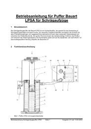
<strong>LED</strong>-<strong>Flatlight</strong>-<strong>Spot</strong> <strong>d60</strong><br />
Brightly lit lift cab, also in the upper area, thanks to a new<br />
<strong>LED</strong> technology with homogenous lighting fi eld<br />
IP20<br />
IP43<br />
160°<br />
RoHS III<br />
Features:<br />
● 3 W homogenous lighting area without dazzling light spots<br />
● Limited resistance to impact and fi re thanks to a 3 mm thick glass guard<br />
● Protected against theft by a fitting holder<br />
● Connection cable plug-and-socket system with 1.7 m intermediate cable<br />
Type Article-no.<br />
<strong>Flatlight</strong>-<strong>Spot</strong>-<strong>d60</strong> natural/warm 465700<br />
<strong>Flatlight</strong>-<strong>Spot</strong>-<strong>d60</strong> daylight 465710<br />
Power unit Article-no.<br />
Power unit C20 for 1-2 spots 465610<br />
Power unit C-60 N-extern for 1-6 spots +<br />
dimmer + port for emergency power supply<br />
16-24 V/3 W<br />
465510<br />
Accessories Article-no.<br />
Additional intermediate cable 1.7 m 465551<br />
Cutout 56 mm dia.<br />
Only 32 mm<br />
mounting depth<br />
Required number of lamps conform to EN 81-1/2<br />
2 natural spots up to 1 m 2 for stainless steel cabs<br />
and longest side 1 m, ceiling height up to 2.2 m<br />
Recommendation:<br />
4 spots / 1.5 m 2<br />
6 spots / 2.0 m 2<br />
A A<br />
B<br />
C<br />
D<br />
E<br />
F<br />
G<br />
*Energy effi ciency class<br />
*Energy effi ciency class<br />
With the <strong>LED</strong> fl atlight series you can achieve energy<br />
effi ciency class A for your lift system.
stainless steel ceiling with <strong>LED</strong> <strong>Flatlight</strong> <strong>Spot</strong> <strong>d60</strong><br />
White aluminium ceiling with <strong>LED</strong> <strong>Flatlight</strong> <strong>Spot</strong> <strong>d60</strong><br />
<strong>LED</strong>-<strong>Flatlight</strong>-<strong>Spot</strong> 4.0<br />
4<br />
51
4<br />
52<br />
4.0 <strong>LED</strong>-<strong>Flatlight</strong>-<strong>Spot</strong><br />
<strong>LED</strong>-<strong>Flatlight</strong>-<strong>Spot</strong> d82<br />
Homogenous round spot fi tting in all 12-60 mm and 68 mm ceiling holes<br />
IP20<br />
IP43<br />
optional<br />
IP54<br />
IP54<br />
160°<br />
Type Enclosure colour Light colour Class Article-no.<br />
<strong>Flatlight</strong>-<strong>Spot</strong>-d82 stainless steel look natural/warm 465800<br />
<strong>Flatlight</strong>-<strong>Spot</strong>-d82 stainless steel look daylight 465805<br />
<strong>Flatlight</strong>-<strong>Spot</strong>-d82 white natural/warm 465810<br />
<strong>Flatlight</strong>-<strong>Spot</strong>-d82 white daylight 465815<br />
<strong>Flatlight</strong>-<strong>Spot</strong>-d82 golden natural/warm 465820<br />
<strong>Flatlight</strong>-<strong>Spot</strong>-d82 golden daylight 465825<br />
<strong>Flatlight</strong>-<strong>Spot</strong>-d82 stainless steel look natural/warm IP54 465801<br />
<strong>Flatlight</strong>-<strong>Spot</strong>-d82 stainless steel look daylight IP54 465806<br />
<strong>Flatlight</strong>-<strong>Spot</strong>-d82 white natural/warm IP54 465811<br />
<strong>Flatlight</strong>-<strong>Spot</strong>-d82 white daylight IP54 465816<br />
<strong>Flatlight</strong>-<strong>Spot</strong>-d82 golden natural IP54 465821<br />
<strong>Flatlight</strong>-<strong>Spot</strong>-d82 golden daylight IP54 465826<br />
Power units Article-no.<br />
Power unit C20 for 1-2 spots 465610<br />
RoHS<br />
Power unit C60 N-extern for 1-6 spots + dimmer + port for emergency power supply<br />
16-24 V/3 W<br />
465510<br />
Accessories Article-no.<br />
Additional intermediate cable 1.7 m 465551<br />
III<br />
A<br />
B<br />
C<br />
D<br />
E<br />
F<br />
A<br />
G<br />
Energy effi ciency class<br />
*Energy effi ciency class<br />
With the <strong>LED</strong> fl atlight series you can<br />
achieve energy effi ciency class A for your<br />
lift system.
stainless steel ceiling with <strong>LED</strong> <strong>Flatlight</strong> <strong>Spot</strong> d82<br />
Very bright cab, also in the upper area, thanks to homogenous <strong>LED</strong> lighting fields<br />
White aluminium ceiling with <strong>LED</strong> <strong>Flatlight</strong> <strong>Spot</strong> d82<br />
Features:<br />
● Solid metal enclosure, surface designstainless steel finish grinding,<br />
white fine structure or gold<br />
● 3 W homogenous <strong>LED</strong> lighting area without dazzling light spots<br />
● Limited resistance to scratching, impact and fire thanks to a 3 mm thick<br />
glass guard, sand blasted<br />
● Protected against theft by a newly developed fitting holder with hidden<br />
hexagon socket screws in the frame<br />
● Connection cable plug-and-socket system including 1.7 m intermediate cable<br />
● Lamps and spots are replaceable on the cab end<br />
Fitting in standard 68 mm dia. holes<br />
(generally required for IP54)<br />
also 12-60 mm dia. for retrofitting<br />
Only 17 mm<br />
mounting depth!<br />
1-10 mm<br />
<strong>LED</strong>-<strong>Flatlight</strong>-<strong>Spot</strong> 4.0<br />
Required number of lamps conform to EN 81-1/2<br />
2 natural spots up to 1 m 2 for stainless steel cabs<br />
and longest side 1 m, ceiling height up to 2.2 m<br />
Recommendation:<br />
4 spots / 1.5 m 2<br />
6 spots / 2.0 m 2<br />
4<br />
53
4<br />
54<br />
4.0 <strong>LED</strong>-<strong>Flatlight</strong>-<strong>Spot</strong><br />
<strong>LED</strong>-<strong>Flatlight</strong>-<strong>Spot</strong> q90<br />
Homogenous square spot for exclusive lift<br />
systems<br />
IP20<br />
IP43<br />
160°<br />
RoHS<br />
Type Enclosure colour Light colour Article-no.<br />
Flatllght-<strong>Spot</strong>-q90 stainless steel look natural/warm 465900<br />
<strong>Flatlight</strong>-<strong>Spot</strong>-q90 stainless steel look daylight 465905<br />
<strong>Flatlight</strong>-<strong>Spot</strong>-q90 white natural/warm 465910<br />
<strong>Flatlight</strong>-<strong>Spot</strong>-q90 white daylight 465915<br />
<strong>Flatlight</strong>-<strong>Spot</strong>-q90 golden natural/warm 465920<br />
<strong>Flatlight</strong>-<strong>Spot</strong>-q90 golden daylight 465925<br />
Power units Article-no.<br />
Power unit C20 for 1-2 spots 465610<br />
Power unit C60 N-extern for 1-6 spots + dimmer + port for emergency<br />
power supply 16-24 V/3 W<br />
Accessories Article-no.<br />
Additional intermediate cable 1.7 m 465551<br />
III<br />
465510<br />
A A<br />
B<br />
C<br />
D<br />
E<br />
F<br />
G<br />
* Energy effi ciency class<br />
*Energy effi ciency class<br />
With the <strong>LED</strong> fl atlight series you can achieve energy<br />
effi ciency class A for your lift system.
Features:<br />
● Solid metal enclosure, surface design stainless steel finish grinding,<br />
white fine structure or gold<br />
● 3 W homogenous <strong>LED</strong> lighting area without dazzling light spots<br />
● Limited resistance to scratching, impact and fire thanks to a 3 mm<br />
thick glass guard, sand blasted<br />
● Protected against theft by a newly developed fitting holder with<br />
hidden hexagon socket screws in the frame<br />
● Connection cable plug-and-socket system including 1.7 m<br />
intermediate cable<br />
● Lamps and spots are replaceable on the cab end<br />
Standard cutout dia. 80 mm<br />
suitable up to 86 mm dia.<br />
stainless steel ceiling ceiling with <strong>LED</strong> <strong>Flatlight</strong> <strong>Spot</strong> q90<br />
Only 17 mm<br />
mounting depth!<br />
1-10 mm<br />
<strong>LED</strong>-<strong>Flatlight</strong>-<strong>Spot</strong> 4.0<br />
Required number of lamps conform to EN81-1/2<br />
2 natural spots up to 1 m 2 for stainless steel cabs<br />
and longest side 1 m, ceiling height up to 2.2 m<br />
Recommendation:<br />
4 spots / 1.5 m 2<br />
6 spots / 2.0 m 2<br />
4<br />
55
4<br />
56<br />
4.0 <strong>LED</strong> <strong>Spot</strong><br />
<strong>LED</strong> <strong>Spot</strong> d77<br />
<strong>LED</strong> spot d77 for cab lighting with integrated emergency lighting function and timesaving<br />
connection system. Exclusive and high-quality designer <strong>LED</strong> spots for lighting<br />
lift cabs.<br />
Owing to the insulation piercing connection system these modern <strong>LED</strong> spots can be<br />
used anywhere on the supply cable, so that there is no need for finishing and commissioning<br />
work at the point where spots are installed. The <strong>LED</strong> spots have an integrated<br />
emergency lighting function and show a high degree of energy efficiency.<br />
There is no need for any special cable finishing work (only one cable for all spots. Insulation<br />
piercing connections allow random tapping points to be chosen).<br />
Highlights<br />
• 5 high-performance <strong>LED</strong>s per spot<br />
• Time-saving insulation piercing connection system<br />
• No commissioning work requiredkein Kommissionierungsbedarf<br />
• Integrated emergency lighting function<br />
• Standard high-quality design<br />
• Category 2 protection against vandalism (optional)<br />
• High energy efficiency<br />
Technical data:<br />
• Radiation angle: 120°<br />
• Number of high-performance <strong>LED</strong>s: 5<br />
• Mounting dia.: 56 mm<br />
• Outside dia.: 77 mm<br />
• Mounting depth: 38 mm<br />
• Performance: 6,5 W normal operation,<br />
1,3 W emergency lighting operation<br />
• Colour of light natural warm, 4000 K<br />
• Cover: Glas<br />
• Type of protection: IP54 on visual end<br />
• Luminous intensity: > 360 Im normal operation /<br />
> 72 Im emergency lighting operation<br />
Special feature robust standard design<br />
• Optionally available: safety against vandalism<br />
safety category 2 conform to<br />
DIN EN 81-71<br />
(highest protection category)<br />
Type Design Article-no.<br />
<strong>LED</strong> <strong>Spot</strong> aluminium d77 aluminium/natural<br />
anodized<br />
<strong>LED</strong> <strong>Spot</strong> aluminium d77 aluminium/natural<br />
anodized<br />
<strong>LED</strong> <strong>Spot</strong> chromium-plated d77 aluminium/<br />
chromium-plated<br />
<strong>LED</strong> <strong>Spot</strong> chromium-plated d77 aluminium/<br />
chromium-plated<br />
prot. against<br />
vandalism<br />
prot. against<br />
vandalism<br />
465000<br />
465005<br />
465100<br />
465105<br />
<strong>LED</strong> <strong>Spot</strong> stainless steel d77 stainless steel 465200<br />
<strong>LED</strong> <strong>Spot</strong> stainless steel d77 stainless steel prot. against<br />
vandalism<br />
465205<br />
power unit Design Articel-no.<br />
<strong>LED</strong> power unit max. 10 spots 465600<br />
<strong>LED</strong> power unit with integrated<br />
emergency-lighting<br />
function<br />
max. 12 spots 465500
Suitable for fl atlight spots <strong>d60</strong> + d82 + q90<br />
for 1-2 spots<br />
Suitable for fl atlight spots <strong>d60</strong> + d82 + q90<br />
optionally with port for external emergency lighting<br />
supply<br />
for 1-6 spots<br />
for 1-10 spots<br />
for 1-12 spots<br />
PRI<br />
<strong>LED</strong> Light Control<br />
wallrafftec.de<br />
Model: C20 Art.-no. 11153<br />
AC/DC <strong>LED</strong> P/S<br />
PRI AC 100 - 240V 50/60Hz<br />
λ=0,58 C Imax=0,17A<br />
Z SEC 240mA - 2...31,5V<br />
SELV<br />
M M SEC<br />
EQUIV. Vomax=33V Wmax=7W<br />
-Thermal protection<br />
100<br />
-Short circuit protection<br />
ta= -20...50°C tc=75°C<br />
Suitable for <strong>LED</strong> spots d77<br />
Suitable for <strong>LED</strong> spots d77<br />
<strong>LED</strong> fl atlight spot power unit C20<br />
● Mini power unit 120 x 35 x 20 mm<br />
100 – 240 V AC / 176 – 264 V DC / 240 mA / 7W<br />
current controlled, short-circuit-proof<br />
for controlling 1-2 <strong>LED</strong> flatlight spots in series,<br />
should individual <strong>LED</strong>s fail inside one spot, the other spots will not fail.<br />
● Pluggable spot connections<br />
● High energy efficiency and long life span<br />
● CE, EMC tested, Made in EU<br />
Type Article no.<br />
Power unit C20 465610<br />
<strong>LED</strong> power unit 4.0<br />
<strong>LED</strong> fl atlight spot power unit C60<br />
● Compact unit 170 x 54 x 52 mm<br />
● Internal power unit 100-240 V AC/24 V DC, short-circuit proof<br />
● 6 parallel individual short-circuit-proof current controllers for controlling 1-6 <strong>LED</strong><br />
flatlight spots, all cable outlets are pluggable<br />
● Infi nitely variable dimmer<br />
● Internal <strong>LED</strong> display for power unit function<br />
● Minimum power consumption<br />
● Power unit TÜV/GS tested<br />
Additional function power unit C60 N-extern<br />
● Automatic change-over of a flatlight spot to emergency<br />
lighting operation should lighting voltage fail, required external supply 15-24 V/3 W<br />
Type Article-no.<br />
Power unit C60 N-extern for 1-6 spots + dimmer + port<br />
for emergency power supply<br />
16-24 V/3 W<br />
<strong>LED</strong> fl atlight spot power unit<br />
Optimized for the operation of <strong>Henning</strong> <strong>LED</strong> spots. High energy effi ciency. Safe operation<br />
requiring no maintenance.<br />
Type Design Article-no.<br />
<strong>LED</strong> power unit max. 10 spots 465600<br />
Feature 10 spots<br />
Performance 60 W adequate for up to 10 spots<br />
Supply voltage 220 V - 240 V AC<br />
Input frequency 50 Hz - 60 Hz<br />
Effi ciency 85%<br />
Type of protection IP 40<br />
Dimensions LxWxH 173 x 76,5 x 30,5 mm<br />
Feature 12 spots<br />
Performance 75 W adequate for up to 12 spots<br />
Supply voltage 88 V - 240 V AC/125 V-373 V DC<br />
Input frequency 47 Hz - 63 Hz<br />
Effi ciency 88,5%<br />
Type of protection IP 53<br />
Dimensions LxWxH 240 x 160 x 90 mm<br />
465510<br />
<strong>LED</strong> fl atlight spot power unit with emergency lighting operation<br />
Optimized for the operation of <strong>Henning</strong> <strong>LED</strong> spots. High energy effi ciency. Safe operation<br />
requiring no maintenance. With emergency lighting operation.<br />
Type Design Article-no.<br />
<strong>LED</strong> power unit max. 12 spots 465500<br />
Special features Automatic change-over from normal to emergency lighting<br />
operation. Temperature-controlled charging circuit for<br />
optimum battery availability. Port for forced cab lighting<br />
shutdown (e.g. for LightWatcher), overcharging protection,<br />
exhaustive discharge protection<br />
4<br />
57
4<br />
58<br />
4.1 <strong>LED</strong> <strong>Flatlight</strong>-Panel<br />
Complete panel – Mounted by one man<br />
stainless steel ceiling ceiling with complete panel<br />
IP40<br />
IP43<br />
Panel features:<br />
130°<br />
RoHS<br />
● Extremely homogenous, high-intensity lighting area<br />
● Bright cab lighting also in the upper area thanks to<br />
wide radiation angle<br />
● Elegant stainless steel enclosure only 30 mm high<br />
● Including polycarbonate pane<br />
● Articel-No.466000 and 466005 has limited resistance to<br />
scratching, impact and fi re thanks to 3 mm tempered<br />
safety glass pane<br />
● Attached using two unobtrusive and hardly accessible<br />
grub screws (on the side)<br />
● Mounted by only one man, ideal also for retrofi tting<br />
● <strong>LED</strong> panel replaceable from the cab end.<br />
● Including power unit 100-240 V, 50-60 Hz<br />
Power unit and current controller are located on the cab roof.<br />
Required number of lamps conform to EN81-1/2<br />
at the time this catalogue is printed:<br />
one panel 300 x 300 for stainless steel cab up to 1.8 m 2<br />
with longest side 1.5 m and 2.2 m ceiling height<br />
III<br />
Type Article-no.<br />
Complete fl atlight panel 300 x 300 natural 466000<br />
Complete fl atlight panel 440 x 440 natural 466002<br />
Complete fl atlight panel 600 x 300 natural 466004<br />
Complete fl atlight panel 300 x 300 daylight 466005<br />
Complete fl atlight panel 440 x 440 daylight 466007<br />
Complete fl atlight panel 600 x 300 daylight 466009<br />
Accessories Article-no.<br />
Panel-dimmer 466010<br />
CN11-24 V-extern change-over box for emergency lighting<br />
operation in case of power failure, external supply 18-30 V/5 W<br />
With the <strong>LED</strong> fl atlight series<br />
you can achieve<br />
energy effi ciency class A<br />
for your lift system.<br />
466015<br />
A A<br />
B<br />
C<br />
D<br />
E<br />
F<br />
G
IP40<br />
IP43<br />
130°<br />
RoHS<br />
Type Articel-no.<br />
<strong>Flatlight</strong> panel 300 x 300 natural 466030<br />
<strong>Flatlight</strong> panel 300 x 300 daylight 466040<br />
<strong>Flatlight</strong> panel 400 x 400 natural 466041<br />
<strong>Flatlight</strong> panel 440 x 440 natural 466042<br />
<strong>Flatlight</strong> panel 440 x 440 daylight 466043<br />
<strong>Flatlight</strong> panel 600 x 300 natural 466060<br />
<strong>Flatlight</strong> panel 600 x 300 natural 466070<br />
<strong>Flatlight</strong> panel 900 x 300 natural 466090<br />
<strong>Flatlight</strong> panel 1200 x 300 natural 466120<br />
<strong>Flatlight</strong> panel 600 x 600 natural 466366<br />
<strong>Flatlight</strong> panel 1200 x 600 natural 466326<br />
Special panels Articel-no.<br />
<strong>Flatlight</strong> panel 616 x 442 natural 466370<br />
<strong>Flatlight</strong> panel 869 x 622 natural 466371<br />
Accessories Articel-no.<br />
Panel-dimmer Dimmer with rotary button and additional remote<br />
control suitable for all panel types<br />
466010<br />
CN11-24 Vexternal<br />
III<br />
Change-over box for the emergency lighting<br />
operation in case of power failure, external supply<br />
18-30 V/5 W suitable for all panels<br />
466015<br />
<strong>Flatlight</strong>-Panel 4.1<br />
<strong>LED</strong> FlatLight-Panel<br />
Attention! Can only be mounted from the cab top ceiling!<br />
Panel features:<br />
● Extremely homogenous, high-intensity lighting area<br />
● Bright cab lighting also in the upper area thanks to wide<br />
radiation angle<br />
● Panel thickness only 15 mm<br />
● High energy efficiency and extremely long life span<br />
● Including power unit 100-240 V, 50-60 Hz<br />
Required number of lamps conform to EN81-1/2 2010 at<br />
the time this catalogue is printed: one panel 300 x 300 for<br />
stainless steel cab up to 1.8 m 2 with<br />
longest side 1.5 m and 2.2 m ceiling height<br />
change-over box CN11 – 24 V – external<br />
from power unit to panel<br />
emergency power supply<br />
With the <strong>LED</strong> fl atlight series<br />
you can achieve<br />
energy effi ciency class A<br />
for your lift system.<br />
A A<br />
B<br />
C<br />
D<br />
E<br />
F<br />
G<br />
weight<br />
Name Datum<br />
Wallraff Lifttechnik+Design<br />
GW 25.11.10<br />
Zeichnungen C60 für Katalog<br />
Blatt<br />
Drawing_ID11074-110203<br />
Blätter<br />
Ers. für: Ers. durch:<br />
Z:\Katalog\Lampenkatalog Zeichng\Zeichnung_ID11075 - 110204.tcd - 04.02.2011 16:50:57<br />
4<br />
59
4<br />
60<br />
4.1 <strong>LED</strong> <strong>Flatlight</strong>-Panel<br />
Frameless panel holders<br />
Best panel protection for your lift system application<br />
In order to maintain the extremely long life span of the <strong>LED</strong> panels, all panel mounting kits are supplied with protective panes.<br />
Also ideal for folding-type false ceilings with a space between false ceiling and normal ceiling from 28 mm upward.<br />
.<br />
stainless steel ceiling with frameless panel holder<br />
IP40<br />
IP54<br />
IP40<br />
IP54<br />
EN81-71 category 2<br />
IP40<br />
IP54<br />
2 2<br />
optionally<br />
1<br />
Step-proof hood<br />
as splash protection<br />
Ceiling cutouts<br />
260 x 260 1160 x 260<br />
560 x 260 560 x 560<br />
860 x 260 1140 x 545<br />
Frameless ceiling mounting kit<br />
consisting of:<br />
mounting angle, set of screws,<br />
including polycarbonate pane,<br />
alternatively with safety glass<br />
pane,resistant to scratching,<br />
impact and fi re, conform to<br />
EN 81-71 category 1<br />
Attachment to the ceiling<br />
The holders are attached to the cab ceiling using a bonding agent or special adhesive tapes. We can be of assistance<br />
with the choice of the adequate bonding mode and with instructions on how to mount the holders to cab ceilings that<br />
are safe to walk on. The attachment angles are provided with bores for an optional attachment using welding pins.<br />
For goods lifts it is recommended to cover the panels with a polycarbonate pane!<br />
Frameless ceiling mounting kit<br />
category 2 protection against<br />
vandalism scope of supplies identical<br />
to frameless ceiling mounting kit category<br />
2 protection against vandalism but<br />
with 10 mm chemically hardened safety<br />
glass pane<br />
The holders are attached to the cab ceiling as with normal kits. Further technical information is provided on request.<br />
Hood for <strong>LED</strong> panels<br />
50 mm high, suitable for all<br />
frameless mounting kits<br />
Special panels<br />
820 x 572<br />
580 x 406<br />
Type with polycarbonate pane Article-no.<br />
Frameless ceiling mounting kit for panel 300 x 300 466031<br />
Frameless ceiling mounting kit for panel 600 x 300 466061<br />
Frameless ceiling mounting kit for panel 900 x 300 466091<br />
Frameless ceiling mounting kit for panel 1200 x 300 466121<br />
Frameless ceiling mounting kit for panel 600 x 600 466161<br />
Frameless ceiling mounting kit for panel 1200 x 600 466162<br />
Frameless ceiling mounting kit for panel 616 x 442 466163<br />
Frameless ceiling mounting kit for panel 869 x 622 466164<br />
Type with safety glass panel Article-no.<br />
Frameless ceiling mounting kit for panel 300 x 300 466038<br />
Frameless ceiling mounting kit for panel 600 x 300 466068<br />
Frameless ceiling mounting kit for panel 900 x 300 466098<br />
Frameless ceiling mounting kit for panel 1200 x 300 466128<br />
Type with 10 mm safety glass panel Article-no.<br />
Frameless ceiling mounting kit for panel 300 x 300 466032<br />
Type Article-no.<br />
Panel hood for panel 300 x 300 466033<br />
Panel hood for panel 600 x 300 466063<br />
Panel hood for panel 900 x 300 466093<br />
Panel hood for panel 1200 x 300 466123<br />
Mounting depth with mounting<br />
set only 26 mm<br />
with hood 50 mm<br />
The <strong>LED</strong> panels with projecting attachments are not<br />
suitable for cab ceilings that are permanently or regularly<br />
exposed to extreme moisture or are installed<br />
outdoors.
2500 x 1500 mm cab with a white aluminium ceiling and two 900 x 300 mm <strong>LED</strong> panels with frameless panel holders<br />
<strong>LED</strong> <strong>Flatlight</strong>-Panel 4.1<br />
4<br />
61
4<br />
62<br />
4.1 <strong>LED</strong> <strong>Flatlight</strong>-Panel<br />
Kabine 2500 x 1500 mm mit Edelstahldecke und zwei <strong>LED</strong>-Panelen 1200 x 600 mm<br />
stainless steel ceiling with 2 <strong>LED</strong> panel and frameless panelholder
IP40<br />
IP54<br />
Mounting kit with extremely stable only<br />
2 mm thick mounting frame,accurately<br />
machined, visible end without weld seams,<br />
fi ne ground or primed stainless steel<br />
holding and protecting the <strong>LED</strong> panel, incl.<br />
polycarbonate glass pane, optionally also<br />
with safety glass pane which is protected<br />
against scratching, impact and fi re conform<br />
to EN81-71 category 1. A clamping system<br />
allows frames to be quickly fi tted.<br />
EN 81-71 category 2<br />
IP40<br />
IP54<br />
2<br />
Step-proof<br />
protective hood<br />
Required<br />
ceiling cutouts<br />
optionally<br />
1<br />
2<br />
317 x 317<br />
617 x 317<br />
917 x 317<br />
1217 x 317<br />
Mounting kit for panel<br />
300 x 300 mm<br />
Vandalism-proof mounting kit<br />
conform to EN81-71 category 2.<br />
Mounting kit with stainless steel or<br />
primed frame for <strong>LED</strong> panels.<br />
Designed like frame mounting kit<br />
but with 10 mm safety glass pane.<br />
Hood for <strong>LED</strong> fl atlight panels<br />
50 mm high, galvanized, suitable<br />
for all panes.<br />
The hood also protects the panel<br />
against splash water from above.<br />
Mounting depth with attachment kit<br />
only 26 mm, 30 mm for category 2<br />
vandalism protection, with hood 50 mm<br />
Landing lighting 4.2<br />
Panel holder with frame<br />
Best panel protection with mounting frame for goods lifts,<br />
car lifts and lifts operated in areas liable to vandalism.<br />
Stainless steel frame Primed frame<br />
Polycarbonate pane Art.-No. 466034 Art.-No. 466035<br />
Safety glass pane Art.-No. 466036 Art.-No. 466037<br />
Mounting kit for panel<br />
600 x 300 mm<br />
Stainless steel frame Primed frame<br />
Polycarbonate pane Art.-No. 466064 Art.-No. 466065<br />
Safety glass pane Art.-No. 466066 Art.-No. 466067<br />
Mounting kit for panel<br />
900 x 300 mm<br />
Stainless steel frame Primed frame<br />
Polycarbonate pane Art.-No. 466094 Art.-No. 466095<br />
Safety glass pane Art.-No. 466096 Art.-No. 466097<br />
Mounting kit for panel<br />
1200 x 300 mm<br />
Stainless steel frame Primed frame<br />
Polycarbonate pane Art.-No. 466124 Art.-No. 466125<br />
Safety glass pane Art.-No. 466126 Art.-No. 466127<br />
Type with 10 mm safety glass pane Article-no.<br />
Stainless steel frame mounting kit for panel 300 x 300 466136<br />
Mounting kit with primed frame for panel 300 x 300 466137<br />
Type Article-no.<br />
Panel hood for panel 300 x 300 466033<br />
Panel hood for panel 600 x 300 466063<br />
Panel hood for panel 900 x 300 466093<br />
Panel hood for panel 1200 x 300 466123<br />
For goods lifts it is recommended to cover the panels with a polycarbonate glass pane.<br />
The <strong>LED</strong> panels with projecting attachments are not suitable for cab ceilings that are permanently or regularly<br />
exposed to extreme moisture or are installed outdoors.<br />
7<br />
frame section<br />
inner end<br />
33<br />
4<br />
63
4<br />
64<br />
4.2 Landing lighting<br />
Goods lift cab – panel with grey-primed frame
Luminary only 46 mm in dia. with magnetic lock retainer<br />
without visible screws, extremely well protected against theft.<br />
IP20<br />
IP42<br />
18<br />
100<br />
30°<br />
RoHS III<br />
Drilling template<br />
for side wall mounting<br />
Features:<br />
● Bright, warm light<br />
● Only 0.8 W power consumption<br />
● Elegant and accurately turned stainless steel<br />
enclosure<br />
● Attached using magnetic lock retainer<br />
● Luminary replaceable from the front end,<br />
also in case of door cases inaccessible from<br />
the rear<br />
● Pluggable connection cable 5 cm with <strong>LED</strong><br />
driver in mini enclosure<br />
● 50,000 h life span acc. to HStAn<br />
Ø 3 countersunk<br />
Ø 18.3 mm (PG16)<br />
(PG16)<br />
1,5-2,0<br />
only 22 mm<br />
mounting depth!<br />
Landing lighting 4.2<br />
Landing Lighting<br />
Type Article-no.<br />
<strong>LED</strong> luminary 0.8 W/10-24 V 465300<br />
Suitable power unit Article-no.<br />
<strong>LED</strong> power unit 100-240 V DC with 1 m supply<br />
cable suitable for 1-16 luminaries<br />
465620<br />
Suitable shaft cables Article-no.<br />
Supply cable 2 x 0.34 mm2, please indicate<br />
required number of meters!<br />
465621<br />
Intermediate cable 3 m, pluggable 465653<br />
Intermediate cable 1 m, pluggable 465651<br />
Duplex distributor, pluggable 465650<br />
4<br />
65
4<br />
66<br />
4.2 Landing Lighting<br />
Landing Lighting<br />
Door case luminary, elegant and fi ligree design,<br />
bright, warm light > 120 lux on the fl oor<br />
IP40<br />
44<br />
30°<br />
44<br />
24<br />
RoHS III<br />
Features:<br />
● Bright, warm light<br />
● Only 0.8 W power consumption<br />
● Elegant and accurately turned stainless steel<br />
enclosure<br />
● Replaceable lamps<br />
● Pluggable connection cable 5 cm<br />
● Different attachment materials<br />
● 50,000 h life span acc. to HStAn<br />
Type Article-no.<br />
<strong>LED</strong> door case luminary 0.8 W/10-24 V 465310<br />
Suitable power unit Article-no.<br />
<strong>LED</strong> power unit 100-240 V DC with 1 m supply<br />
cable suitable for 1-16 door case luminaries<br />
465620<br />
Accessories Article-no.<br />
Supply cable 2 x 0.34 mm2, please indicate<br />
required number of meters!<br />
465621<br />
Intermediate cable 3 m, pluggable 465653<br />
Intermediate cable 1 m, pluggable 465651<br />
Duplex distributor, pluggable 465650<br />
A A<br />
B<br />
C<br />
D<br />
E<br />
F<br />
G
IP44<br />
IP44<br />
30<br />
45°<br />
RoHS<br />
Features:<br />
● Exclusively designed stainless<br />
steel enclosure<br />
● Protected by safety glass<br />
● Suitable for lamps GU 10<br />
230V/50 Hz max. 35 W<br />
Lamp GU10<br />
Energy-saving class B<br />
long life span, 45° radiation angle<br />
230 V / 50 Hz<br />
Landing Lighting 4.2<br />
Landing Lighting<br />
Type Article-no.<br />
Stainless steel wall-mounted luminary 465320<br />
Suitable lamps Light colour Article-no.<br />
<strong>LED</strong> GU10-6-230 V-w <strong>LED</strong> lamp 6 W warm 465321<br />
<strong>LED</strong> GU10-6-230 V-d <strong>LED</strong> lamp 6 W cool 465322<br />
4<br />
67
4<br />
68<br />
4.3 Shaft Illumination<br />
Shaft Illumination<br />
Technical Characteristics:<br />
• Fluorescent lamps construction type T5, received power 21W only, very low<br />
consumption<br />
• Shrouded against mechanical impact<br />
• Suitable for horizontal lift shaft section 2,5m x 2m, for bigger horizontal<br />
sections either distance between lamps is to be reduced or a second shaft<br />
illumination circuit to be installed<br />
• Electronic ballast, no starter required<br />
• Weight per lamp: 380 g only<br />
• Immediate start without flicker and without strobe light effect<br />
• Quick and easy installation<br />
• Earthed, two-core wiring<br />
• Kit includes 10 m mains line as well as connecting lines<br />
• Dimensions (L x H x W) 920 x 24 x 42 mm<br />
Type number of<br />
lights<br />
Strip Light 21 W,<br />
Incl. connecting line and mounting plates<br />
Article-no.<br />
337000<br />
Mains line 10 m, with Euro-plug 337010<br />
Shaft Illumination Kit for shafts of up to 6,8 m height 3 337100<br />
Shaft Illumination Kit for shafts of up to 9,7 m height 4 337110<br />
Shaft Illumination Kit for shafts of up to 12,6 m height 5 337120<br />
Shaft Illumination Kit for shafts of up to 15,5 m height 6 337130<br />
Shaft Illumination Kit for shafts of up to 18,4 m height 7 337140<br />
Shaft Illumination Kit for shafts of up to 21,3 m height 8 337150<br />
Shaft Illumination Kit for shafts of up to 24,2 m height 9 337160<br />
Shaft Illumination Kit for shafts of up to 27,1 m height 10 337170<br />
Shaft Illumination Kit for shafts of up to 30,0 m height 11 337180<br />
Shaft Illumination Kit for shafts of up to 32,9 m height 12 337190<br />
Strip Light, Black<br />
Technical Characteristics:<br />
• Black casing, ideal for illuminating shafts of glass elevators<br />
• Received power 1 x 36 W<br />
• Dimensions (L x H x W) 1290 x 35 x 61 mm<br />
• Lines H05VV-F 3G1,5 mm² firmly connected<br />
• Line length 2 x 1,15 m with 3-pole plug / connector<br />
• Equipped with fixation angles<br />
Type Article-no.<br />
Strip Light black 337050<br />
Mains Line 10 m 337055
LIGHTWatcher<br />
LIGHTWatcher 4.4<br />
Since the EU directive 2002/91/EG was published, energy efficiency is in the focus of building engineering and management experts. With the publication of VDI 4707<br />
in March 2009 this issue is also of topical interest for lift systems. Today systems and plants which are part of the building inventory are considered to consume large amounts<br />
of energy.<br />
In lift systems this consumption can mostly be put down to the lift car lighting system.<br />
The LIGHTwatcher allows you to simply turn off the lift car lights when these are not needed without a major installation expenditure, new<br />
cables or control system modifications being necessary.<br />
What shares in the energy consumption of a lift at a<br />
standstill?<br />
Operation of the LightWatcher:<br />
The LIGHTwatcher is installed directly on top of the lift car roof allowing lift car<br />
movements to be detected by the three integrated acceleration sensors. The<br />
sensors are so sensitive that they even identify movement of the lift car<br />
doors.<br />
The lift car lights are turned on as soon as a movement is detected inside the<br />
lift car. The switching threshold for the detection of movements is directly set on<br />
the LIGHTwatcher.<br />
Upon expiry of a time span adjusted by you, the lights are turned off again when<br />
no further movements of the lift car and doors are detected.<br />
The installation of the unit requires the electric lighting circuit to be opened and<br />
the LIGHTwatcher to be inserted. Since the unit is powered by the electrical<br />
lighting circuit, no extra cables are needed.<br />
Apart from the car lights the LIGHTwatcher can turn off another consumer.<br />
An additional third contact is provided which in the energy saving mode connects<br />
another consumer e.g. activating the emergency light instead of the regular lift<br />
car lights.<br />
Three potential-free inputs are available for special applications requiring other<br />
sensors than the acceleration sensors to activate the lights.<br />
• Event-controlled cutout of lights when the lift is stationary<br />
• Minimisation of the stationary demand conform to VDI 4707<br />
• Independent detection of lift car and door movements<br />
• There is no need to tamper with the lift system electronics<br />
• Simple installation directly in the electrical lighting circuit<br />
• Cutout behaviour can be influenced via control inputs<br />
• Suitable for being attached to tophat rails and walls<br />
Highlights of the LightWatcher:<br />
Supply voltage 230 V AC/optionally 110V AC<br />
Power input 2 VA<br />
Relay outputs 3<br />
Cutout delay 1 - 10 min<br />
Max. switching voltage 250 V AC<br />
Max. making current 15 A<br />
Max. permanent current 10 A<br />
Max. switching capacity (ohmic) 2500 VA<br />
Max. switching capacity (ind.) 500 VA<br />
Min. switching load 0.3 W<br />
Additional control inputs 3<br />
Control voltage 12 V - 230 V AC/DC<br />
L x W x H (mm) 106 x 90 x 58<br />
Optional accessories:<br />
Installation kit:<br />
• 1 x tophat rail<br />
• 3 x pan-head tapping screws with cross recession<br />
• 6 x standard light clamps<br />
Type Article-no.<br />
LIGHTWatcher 230 V 460000<br />
LIGHTWatcher 110 V 460000-110<br />
Installationskit for LIGHTWatcher 460100<br />
4<br />
69
CAB EQuIPMEnT<br />
5<br />
71
5<br />
72<br />
5.0 Landing Indicator<br />
Landing Indicator<br />
VV3 Landing Indicator<br />
• Indicates landings, direction arrows and changing text messages<br />
• To be installed in the cabin or on landings<br />
• Easy programming by keys on the back or by means of the SafeLine Pro<br />
Software<br />
• Text messages can be changed by the user by means of SafeLine Pro<br />
• Integrated signal for connection to a separate loudspeaker<br />
• Input signals: BCD-code, Gray-code or decimal code<br />
• Quick and easy installation by click-on mechanism to the frontplate or the<br />
installation frame<br />
• Dimensions H x W x D: 53 x 53 x 32 mm<br />
• Installation plate and loudspeaker to be ordered separately<br />
VV3 Frontplate<br />
• Dimensions H x W: 150 x 80 mm<br />
• Distance between notches: 130 mm<br />
• Material: stainless steel brushed<br />
• Recess suitable for VV3<br />
VV3 Frame For Superimposed Wall-Mounting<br />
• Cranked frame with frontplate made from stainless steel.<br />
• Recess suitable for VV3 (48 x 48 mm).<br />
• Dimensions H x W x D: 150 x 90 x 28 mm.<br />
Type Article-no.<br />
VV3 Landing indicator, red 337300<br />
VV3 Landing indicator, blue 337301<br />
VV3 Frame for superimposed wall-mounting 337302<br />
VV3 Frontplate for flush mounting 337303<br />
VV3 Loudspeaker for door signal, for retrofitting 337304<br />
VV3/4 Programming cable 2 m, serial 337305<br />
RS 232/USB Adapter 337314
FD4 Landing Indicator & Voice Announcement<br />
Landing Indicator 5.0<br />
Landing Indicator<br />
• Landing indicator with integrated voice announcement of 60 seconds entire<br />
length provided that normal wave-files are used<br />
• Indicates landing, direction arrows and changing text messages<br />
• To be easily programmed by keys on the back or by means of SafeLine Pro<br />
Software<br />
• Text messages and voice announcements can be changed to user-defined<br />
messages by SafeLine Pro Software<br />
• Integrated arrival signal conforming EN81-70, for connection to a separate<br />
loudspeaker<br />
• Quick and easy installation by click-on mechanism to the frontplate or the<br />
installation frame<br />
• Dimensions H x W x D: 61 x 80 x 29 mm<br />
• Frontplate and loudspeaker to be ordered separately<br />
unit With Loudspeaker For Superimposed Wall-Mounting<br />
unit With Loudspeaker For Flush Mounting<br />
FD4 Frontplate<br />
Dimensions H x W: 180 x 100 mm<br />
Distance between notches: 180 mm<br />
Material: stainless steel brushed<br />
Recess suitable for FD4<br />
FD4 Frame For Superimposed Wall-Mounting<br />
Cranked frame with plate made from stainless steel.<br />
Recess suitable for FD4.<br />
Dimensions H x W x D: 150 x 90 x 28 mm.<br />
Type Article-no.<br />
FD4 Landing indicator, red 337505<br />
FD4 Landing indicator, blue 337506<br />
FD4 Frame for superimposed wall-mounting 337308<br />
FD4 Frontplate, for flush mounting 337309<br />
FD4 Unit with loudspeaker for flush mounting, red 337500<br />
FD4 Unit with loudspeaker for flush mounting, blue 337501<br />
FD4 Unit with loudspeaker for superimposed wall-mounting, red 337510<br />
FD4 Unit with loudspeaker for superimposed wall-mounting, blue 337511<br />
VV3/4 Programming cable 2 m, serial 337305<br />
5<br />
73
5<br />
74<br />
5.0 Landing Indicator<br />
Encoder PG1<br />
Encoder PG1 For Landing Indicator FD4<br />
For making your elevator conform with EN81-70.<br />
Installation time is less than one (1) hour.<br />
• Stand-alone system does not depend on the existing elevator control<br />
• nor does it mesh in it<br />
• No free cores of the travelling cable required<br />
Scope Of Supply:<br />
• Encoder PG1<br />
• Kevlar-cord 30 m<br />
• Tensioning device<br />
Technical Characteristics<br />
Supply voltage 24 VDC<br />
Dimensions H x W x D 80 x 100 x 190 mm<br />
Type Article-no.<br />
Encoder PG1 337520
Comparison of SafeLine MX and SL6<br />
SafeLine MX SL6<br />
Power Supply 10-30 VDC l 10-30 VDC l<br />
PSTN connection Standard l 10-30 VDC l<br />
GSM connection GSM-Line l 10-30 VDC l<br />
Pictograms Standard l 10-30 VDC l<br />
Emergency power MUPS/BL1 l 10-30 VDC l<br />
Intercom I-com, Comphone l 10-30 VDC l<br />
Additional inputs 10-30 VDC l 10-30 VDC l<br />
Additional outputs 10-30 VDC l 10-30 VDC l<br />
Power supply emergency<br />
illumination<br />
10-30 VDC l 10-30 VDC l<br />
External Pictograms 10-30 VDC l 10-30 VDC l<br />
l = Standard<br />
l = Optional<br />
l = Not available<br />
Emergency Lift Telephone 5.1<br />
Emergency Lift Telephone<br />
Safeline offers two series MX2 and SL3000 for differing applications.<br />
From the adjoining table you can read the functions resp. the additional<br />
components required.<br />
We recommend to apply the Safeline MX2 series especially for the modernization<br />
of existing elevators, whereas the series SL3000 is distinguished by its functions<br />
emergency power supply and additional intercom stations.<br />
Emergency Lift Telephone Safeline MX (Superimposed)<br />
• All functions required integrated in one unit: telephone interface, microphone/<br />
loudspeaker, PC-interface, pictogram, recording of spoken messages, keypad<br />
for programming<br />
• Conforms with every requirement stipulated by the European standards<br />
EN81-28 and EN81-70<br />
• Unit for superimposed installation, superimposed height 18 mm only<br />
• Up to nine (9) SafeLine MX can be connected to one and the same telephone<br />
line<br />
• Alarm protocols P100, CPC and Q23 for communication with many types of<br />
emergency call centres. If required, we will be prepared to check, whether<br />
the system is compatible with your emergency call centre.<br />
• On-site recording of identification messages<br />
• Wireless emergency call for GSM-module possible as an option.<br />
Please check in advance, whether your authorities for acceptance tests will<br />
accept GSM-emergency calls.<br />
Technical Data of SafeLine MX:<br />
Supply voltage: 11 - 30 VDC<br />
Power consumption: max. 50 mA<br />
Loudspeaker: min 0,25 W<br />
Dimensions H x W x D: 130 x 78 x 18 mm<br />
Type Article-no.<br />
Safeline MX² Emergency Call Telephone With Pictogram,<br />
Superimposed Execution (SLMX-Pic)<br />
337330<br />
5<br />
75
5<br />
76<br />
5.1 Emergency Lift Telephone<br />
Emergency Lift Telephone<br />
Emergency Lift Telephone MX² (Flush Installation)<br />
• All functions required integrated in one unit: telephone interface, microphone/<br />
loudspeaker, PC-interface, pictogram, recording of spoken messages,<br />
keypad for programming<br />
• Conforms with every requirement stipulated by the European standards<br />
EN81-28 and EN81-70<br />
• Unit for flush installation; installation depth 15 mm only<br />
• Up to nine (9) SafeLine MX² can be connected to one and the same telephone line<br />
• Alarm protocols P100, CPC and Q23 for communication with many types of<br />
emergency call centres. If required, we will be prepared to check, whether<br />
the system is compatible with your emergency call centre.<br />
• On-site recording of identification messages<br />
• Wireless emergency call for GSM-module possible as an option.<br />
Please check in advance, whether your authorities for acceptance tests will<br />
accept GSM-emergency calls.<br />
Technical Data of SafeLine MX<br />
• Voltage supply: 11 - 30 VDC.<br />
• Power consumption: max 50 mA.<br />
• Loudspeaker: min 0,25 W.<br />
• Dimensions H x W x D: 155 x 90 x 16 mm.<br />
Type Article-no.<br />
Safeline MX2 Emergency Call Telephone with Pictogram,<br />
Flush Installation (SLMX-Rec-Pic)<br />
Emergency Lift Telephone Safeline MX²<br />
(Rear Panel Installation)<br />
337320<br />
• All functions required integrated in one unit: telephone interface, microphone/<br />
loudspeaker, PC-interface, pictogram, recording of spoken messages,<br />
keypad for programming<br />
• Conforms with every requirement stipulated by the European standards<br />
EN81-28 and EN81-70<br />
• Unit for rear panel installation; depth 15 mm only<br />
• Up to nine (9) SafeLine MX² can be connected to one and the same telephone line<br />
• Alarm protocols P100, CPC and Q23 for communication with many types of<br />
emergency call centres. If required, we will be prepared to check, whether<br />
the system is compatible with your emergency call centre.<br />
• On-site recording of identification messages<br />
• Wireless emergency call for GSM-module possible as an option.<br />
Please check in advance, whether your authorities for acceptance tests will<br />
accept GSM-emergency calls.<br />
Technical Data<br />
Voltage supply: 11 - 30 VDC<br />
Power consumption: max 50 mA<br />
Alarm button: can be set either as a N/O switch<br />
Type Article-no.<br />
Emergency Call Telephone Safeline MX2, (Rear Panel<br />
Installation) (SLMX_COP)<br />
or as a N/C switch<br />
Loudspeaker: min 0,25 W<br />
Dimensions H x W x D: 100 x 80 x 16 mm<br />
337325
Mobile Telephone Module GL1<br />
Emergency Lift Telephone 5.1<br />
• GSM-option for our telephones in elevators<br />
• Outstanding cost savings possible in comparison to fixed phone lines, thanks<br />
to prepaid cards<br />
• This unit can replace a fixed phone line and can be installed in the machine<br />
room, elevator shaft or on the car roof. Up to 9 elevators can be connected to<br />
one GL1 module<br />
• Suitable for preliminary or durable installation<br />
• Perfectly facilitates “test runs” before installing fixed phone lines<br />
• GL1 is installed in a rigid steel casing<br />
• Includes a twin-band aerial with 2,5 m cable, Twin-band GSM-module<br />
(900/1800 MHz) and GPRS<br />
• Power supply: 12 / 24 VDC<br />
• Dimensions H x W x D: 116 x 140 x 35 mm<br />
•<br />
Remarks:<br />
Although transmittal from stationary GSM-units is very reliable, not every<br />
testing authority will admit them.<br />
Please clarify with your testing authority, before you order this module.<br />
Do not hesitate to contact us in case of possible questions.<br />
Type Article-no.<br />
Safeline GL1 337350<br />
Mobile Telephone Module GL4 with Integrated Emergency Power Supply<br />
• Like Mobile Telephone Module GL1<br />
• Includes GSM-aerial and 3 m cable<br />
• Voltage supply 20-30 VDC<br />
• Dimensions 47 x 115 x 92 mm<br />
Mobile Telephone Module GL5 with Integrated Emergency Power Supply<br />
• Like Mobile Telephone Module GL1<br />
• Includes GSM-aerial and 3 m cable<br />
• Voltage supply 230 V AC<br />
• Dimensions 47 x 115 x 92 mm<br />
GSM-Module<br />
Type Article-no.<br />
GL4 337352<br />
GL5 337355<br />
5<br />
77
5<br />
78<br />
5.1 Emergency Lift Telephone<br />
Internal communication module<br />
Optional module for establishing a voice communication between the lift car<br />
and machine room in conjunction with the hand-operated unit art. no. 337360<br />
Dimensions H x W x D: 115 x 100 x 35 mm<br />
Comphone hand-operated unit<br />
• Optimum hand-operated unit for a comfortable programming of emergency phones<br />
• Establishing an internal voice communication (machine room – lift car) in<br />
conjunction with communication module art. no. 337340<br />
• Dimensions H x W x D: 65 x 65 x 200 mm<br />
Type Article-no.<br />
IC 2 337384<br />
Comphone 337360<br />
Emergency power supply unit uP2<br />
For a power supply to SafeLine MX and GL1 with 12 V in case of power failure.<br />
Can supply power to an emergency light for as long as one hour.<br />
With short-circuit and overheating protection.<br />
Type Article-no.<br />
UP 2 337381<br />
Emergency Stop Button<br />
The emergency stop button can be connected to the emergency call telephone.<br />
• can be installed on top or at the bottom of the car<br />
• can be connected in parallel with the emergency stop button in the cabin<br />
to establish an emergency call possibility as from the elevator shaft or the<br />
car roof. Thanks to the high quality of the language transmittal of Safeline,<br />
communication from outside the cabin is enabled ad well<br />
Technical Data:<br />
Dimensions H x W x D 69 x 35 x 27 mm<br />
Voltage supply max 30 VDC, 0,5Ah<br />
Contact NO (normally open)<br />
Type Article-no.<br />
Emergency Stop Button (Button01) 337361
Emergency Lift Telephone 5.1<br />
Fire alarm system SafeLine SL6 to meet En81-28, En81-70 and En81-72 standards<br />
• Up to 6 intercom units per SL6 main station<br />
• Announcements can be transmitted to all units when the system is activated<br />
PSTN and GSM connections are possible at the same time<br />
• Programming via USB interface<br />
• Integrated function for evacuations and fi re brigade intercom<br />
• Simple installation thanks to two-wire cabling<br />
• Steel casing<br />
• <strong>LED</strong> for a visible display on the system<br />
Telephone station<br />
Conforms with all requirements of EN81-28 and EN81-70.<br />
Safeline SL 6<br />
High quality of language transmittal enables simple and precise communication.<br />
Plays back a recorded message identifying the elevator cabin in clear words.<br />
No DTMF-based identifi cation, therefore no computer required on the recipients<br />
side.<br />
The telephone unit without handset can be used by handicapped passengers or<br />
passengers in distress.<br />
• Integrated loudspeaker and microphone<br />
• Frontplate made of stainless steel<br />
• Status indication (yellow and green <strong>LED</strong>s) and pictrograms<br />
Type Articleno.<br />
SL 6 Cabin unit PSTN and GSM 337600<br />
SL 6 Telephone station back counter mounting 337601<br />
SL 6 Telephone station cab/elevator shaft 337602<br />
SL 6 Telephone station cab/elevator shaft/alarm button 337603<br />
SL 6 Telephone station installation on site 337604<br />
SL 6 Telephone station 337605<br />
SL 6 Telephone station countertop mounting 337606<br />
SL 6 Telephone station countertop mounting/emergency <strong>LED</strong> 337607<br />
SL 6 Telephone station countertop mounting/pictogram 337608<br />
SL 6 Telephone station countertop mounting/pictogram/alarmbutton 337609<br />
SL 6 Telephone station countertop mounting/pictogram/framework<br />
illumination<br />
337610<br />
SL 6 Alarm button elevator shaft/cab roof 337611<br />
5<br />
79
5<br />
80<br />
5.1 Emergency Lift Telephone<br />
Safeline Fire<br />
Fire alarm system SafeLine Fire to meet En81-72 standards.<br />
• Connecting up to 4 intercom units per lift system.<br />
• Announcements can be transmitted to all units<br />
when the system is activated<br />
• Steel casing<br />
• <strong>LED</strong> for a visible display on the system<br />
Telephone station<br />
Conforms with all requirements of EN81-28 and EN81-70.<br />
High quality of language transmittal enables simple and precise communication.<br />
Plays back a recorded message identifying the elevator cabin in clear words.<br />
No DTMF-based identification, therefore no computer required on the recipients<br />
side.<br />
The telephone unit without handset can be used by handicapped passengers or<br />
passengers in distress.<br />
• Integrated loudspeaker and microphone<br />
• Frontplate made of stainless steel<br />
• Status indication (yellow and green <strong>LED</strong>s) and pictrograms<br />
Type Article-no.<br />
SL Fire cabin unit 337512<br />
Sprechstelle entrance 337514<br />
Sprechstelle floor 337515<br />
Sprechstelle cab 337513
Assembly tools 5.2<br />
Plumb-Holding Device for Rail Alignment<br />
• Device to fix the plumb line to and let it fall from there<br />
• The steel plumb-line runs in the borehole of the device and is tensioned with<br />
the turnbuckle<br />
• For guide rails up to 19 mm<br />
• Diameter of plumb-line 0,7 mm<br />
• length of plumb-line 130 m<br />
Type Article-no.<br />
Plumb-holding device, partable 337760<br />
Plumb-holding device, firm 337765<br />
Turnbuckle 337770<br />
Plumb-line 337775<br />
5<br />
81
5<br />
82<br />
5.2 Assembly tools<br />
Door Stopper<br />
• For fixing landing doors in open position<br />
• Is clipped in the groove of the landing door sill to make sure that the landing<br />
door does not snap shut<br />
• Suits grooves of 4 mm width and more<br />
• Made from aluminium, therefore very light<br />
Type Article-no.<br />
Door Stopper 337720<br />
Angle Measuring Device For V-Grooves In Traction<br />
Sheaves<br />
• Measuring and checking V-grooves with and without undercut<br />
• Measuring range: 25°-70°<br />
• Sleeve, padded, 90 mm x 90 mm<br />
Type Article-no.<br />
Angle Measuring Devic 500000
Rail Alignment Indicator<br />
Assembly tools 5.2<br />
Rail alignment indicator facilitate the aligning of the guide rails accurately to<br />
one another. Each two indicators are fixed to a metal tube (d = 28 mm, not<br />
included) of an appropriate length. With their flanges they are held to the<br />
guide rails.<br />
The alignment is accurate, if both indicators are centered. Device Nr. 337810<br />
can also be used for a plumbing line, so that not only the alignment of the<br />
guide rails to one another can be checked, but also their vertical alignment.<br />
The indicator is delivered in pairs.<br />
Type Article-no.<br />
Rail Alignment Indicator, standard 337800<br />
Rail Alignment Indicator, on Ballbearings 337805<br />
Rail Alignment Indicator, with Plumbing Device 337810<br />
5<br />
83
5<br />
84<br />
5.2 Assembly tools<br />
Railmaster DJ-A (Kit)<br />
• Portable high-precision measuring laser facilitating erection and checking of<br />
elevator guide rails<br />
• Serves for checking the coplanitarity of guide rails (parallelity and planitarity)<br />
• Easy to operate<br />
• Contributes to easy, quick and cost-saving erection of guide rails<br />
• Supplementary device to determine the distance between guide rails by steel<br />
scale tape<br />
• Packed in a plastic case for transport<br />
Type Article-no.<br />
Railmaster 500010<br />
Car Block<br />
• A supporting block for car or counterweight<br />
• To be fixed to the guide rail by a screw joint<br />
• To be applied not other than in pairs<br />
Technical Data:<br />
Supporting capacity 11 t<br />
Tensioning range 16 -19 mm<br />
Weight 10,5 kg<br />
Type Article-no.<br />
Car Block 337820
False Car,<br />
A Rail-Guided Installation Platform<br />
FALSE CAR 5.3<br />
• Facilitates the erection of guide rails in the elevator shaft<br />
• Made of aluminium<br />
• Safeguards itself automatically on the guide rails already erected<br />
• Lifted by a rope-hoist<br />
• Entirely detachable for easy transport from site to site<br />
• Illustrating video for free download from www.henning-gmbh.de<br />
• Optionally available for rent<br />
Technical Data<br />
Capacity 680 kg<br />
Weight 105 kg<br />
Guide rails 16 - 30 mm<br />
Type Article-no.<br />
False Car 337830<br />
Protective Canopy<br />
• Protecting from falling objects<br />
• Includes a railing<br />
• Canopy planking to be provided by customer/building contractor<br />
Type Article-no.<br />
Protective Canopy 337835<br />
Adjustable Platform<br />
• Adjustable platform made from aluminium<br />
• Adjusting range (depending on the installation site)<br />
• 180 – 243 cm x 155 – 190 cm or<br />
• 161 – 233 cm x 193 – 274 cm<br />
Type Article-no.<br />
Adjustable Platform 337840<br />
5<br />
85
5<br />
86<br />
5.4 Handrail for the cabin roof<br />
handrail for the cabin roof,<br />
extendable and hinged<br />
• extendable from 600 to 1100 mm<br />
• width adjustable from 800 to<br />
• 1500 mm (profiles will fit into each other)<br />
• easy fixing on either side with two enclosed clip angles<br />
• saftey contact adjustable depending on desired inclination (0°-90°)<br />
• two contacts switches for the registration of plugged-in rather<br />
the reeled-out position<br />
• 2 x 3 m cable H07RN-F 2 x 1 mm²<br />
• detachable clip angle<br />
• basebord 10 cm<br />
• delivery with attachment screws<br />
Type Article-no.<br />
handrail, extendable and hinged<br />
height: 600 - 1100 mm - length: 800 - 1500 mm<br />
335100
Handrail for the cabin roof 5.4<br />
handrail for the cabine roof,<br />
adjustable in length and height<br />
• ectendable from 280 to 700 mm or from 600 to 1100 mm in height<br />
• width adjustable from 500 to 1000 mm or from 800 to 1600 mm<br />
(profiles will fit into each other)<br />
• two contact switches for the registration of the plugged-in rather the<br />
reeled-out position<br />
• easy fixing on either side with two enclosed clip angles<br />
• 2 x 3 m cable H07RN-F 2 x 1 mm²<br />
• basebord 10 cm<br />
• delivery witch attachment screws<br />
Type Article-no.<br />
handrail, adjustable<br />
height: 380 - 700 mm - length: 500 - 1000 mm<br />
handrail, adjustable<br />
height: 380 - 700 mm - length: 800 - 1600 mm<br />
handrail for the cabine roof, static<br />
335110<br />
335120<br />
• length / width adjustable up to 1950 mm (profiles will fit into each other)<br />
• height 1110 mm<br />
• easy fixing on cabine roof<br />
• basbord 10 cm<br />
• delivery with attachmend screws<br />
• a tiangular handrail consists of one backside Art.-No. 335200 and two side<br />
• parts Art.-No. 335250<br />
• the backside Art.-No. 335200 can also be used as a stand alone handrail<br />
Type Article-no.<br />
handrail, static<br />
height: 1100 mm - length: - 2000 mm, back part<br />
handrail, static<br />
height: 1100 mm - length: - 2000 mm, side part<br />
335200<br />
335250<br />
5<br />
87
5<br />
88<br />
5.5 Car Apron<br />
Car Apron, Bipartite Or Tripartite<br />
In compliance with DIN EN 81-1/2 8.4, the elevator car has to be equipped with<br />
a Apron under the car sill of at least 0,75 m height.<br />
In case of low shaft pits, this skirting can be telescoping.<br />
• Complete kit<br />
• Apron sheets from stainless steel (zinc-plated)<br />
• 2 adjustable supports (3 mm thick) with pivoting fixing angles<br />
• 2 safety contacts monitoring the extended position<br />
• Fitting time 30 to 40 min.<br />
• Connecting cable HO7RN-F 2 x 1 mm², 3 m long is included<br />
• Silent operation<br />
• Height 750 mm<br />
• Telescoped dimension<br />
• of bipartite execution 450 mm<br />
• of tripartite execution 390 mm<br />
• Executed either in stainless steel or painted in black (upon inquiry)<br />
Type Applied for Article-no.<br />
Car Apron, Zinc-Plated, Bipartite<br />
Apron bipartite PL800, h = 450 mm door opening 800 mm 335400<br />
Apron bipartite PL800, h = 450 mm door opening 900 mm 335410<br />
Apron bipartite PL800, h = 450 mm door opening 1000 mm 335420<br />
Apron bipartite PL800, h = 450 mm door opening 1100 mm 335430<br />
Type Applied for Article-no.<br />
Fahrkorbschürze, verzinkt, 3-teilig<br />
Apron tripartite PL700, h = 390 mm door opening 700 mm 335445<br />
Apron tripartite PL800, h = 390 mm door opening 800 mm 335450<br />
Apron tripartite PL900, h = 390 mm door opening 900 mm 335460<br />
Apron tripartite PL1000, h = 390 mm door opening 1000 mm 335470<br />
Apron tripartite PL1000, h = 390 mm door opening 1100 mm 335480<br />
Car Apron, Invariable<br />
• Complete Kit<br />
• Made from zinc-plated steel sheet metal, Execution in stainless steel upon<br />
inquiry<br />
• 2 adjustable supports with pivoting fixing angles<br />
• Fitting time 30 to 40 min<br />
• Height 750 mm<br />
Type Applied for Article-no.<br />
Car Apron, Zinc-Plated, Invariable<br />
Apron invariable h = 750 mm, b = 800 mm door opening 800 mm 335510<br />
Apron invariable h = 750 mm, b = 900 mm door opening 900 mm 335520<br />
Apron invariable h = 750 mm, b = 1000<br />
mm<br />
door opening 1000 mm 335530<br />
Apron invariable h = 750 mm, b = 1100 mm door opening 1100 mm 335540
196 mm<br />
294 mm<br />
99 mm<br />
521 mm 479 mm<br />
140 mm<br />
241 mm<br />
257 mm<br />
219 mm<br />
dimensions (mm)<br />
124 mm<br />
31 mm<br />
442 mm<br />
ROPE GRIPPER TM<br />
Rope brake conform to A3<br />
ROPE GRIPPER TM 5.6<br />
Protection against overspeed and uncontrolled lift car movements<br />
• Protective device preventing an inadvertent movement of the lift car<br />
at landings when doors are opened<br />
• Protective device preventing ropes from slipping on the traction sheave<br />
• Protective device preventing the lift car from overspeeding during upward rides<br />
Dependable locking of ropes<br />
• Causes no rope wear<br />
• Does not expose drives and ropes to excessive loads<br />
• Easily replaceable, asbestos-free and nonmetallic linings<br />
• Ropes are quickly and carefully locked<br />
Compact – one-piece design<br />
• No separate hydraulics<br />
• Adapts to almost any kind of application<br />
• Easily installed<br />
Mechanically adjustable<br />
• Immediately trips in case of power failure<br />
• Smooth and reliable operation<br />
Electrically operated<br />
• Automatic normal operation when power<br />
supply is restored<br />
• Manually reset in case of fault<br />
230V AC – 50 Hz – 3 A<br />
Technical data (max. values):<br />
Rope Gripper TM G 620 suspension 1 :1 suspension 2 :1<br />
Nominal speed max. 1,78 m/s 1,27 m/s<br />
Tripping speed max. 2,04 m/s 1,54 m/s<br />
Nominal lift car load max. 1134 kg 2268 kg<br />
Total load from lift car, nominal<br />
load, counterweight,<br />
compensation rope max.<br />
5216 kg 10432 kg<br />
Doorway max. 254 mm ± 254 mm ±<br />
Further types for low/high speed/car load on request.<br />
Type Article-no.<br />
ROPE GRIPPER TM G 620 rope brake 334100<br />
5<br />
89
General information and imprint<br />
The products in this catalogue conform to Lift Directive 95/16/EG Annex 1 Item 4.8 and to DIN EN81-1-1:1998 and/or DIN EN2:1998 Item 8.17 and some marked products conform to DIN EN81-<br />
71:2007 Items 5.4.1 & 5.4.4.<br />
It is principally possible that products in other countries may call for additional or other standards to be taken into consideration. This needs to be verified by the user.<br />
The illustrations, drawings and measurements included in the catalogue have been made out with due care without claiming that they are authoritative.<br />
Cab wall reflections may differ from the catalogue’s illustrations depending on the surface, luminaries, position of the luminaries and dimming grade.<br />
Subject to errors, improvements and technical modifications. Supplementary technical data on the individual products can be supplied on request. <strong>Henning</strong> <strong>GmbH</strong> & Co. KG cannot be held liable for<br />
incidental or consequential damages suffered in connection with the use of the catalogue.<br />
All rights reserved. Without prior written consent of <strong>Henning</strong> <strong>GmbH</strong> & Co. KG it is not allowed to copy, duplicate, translate or store in electronic media this catalogue in its entirety or in parts.<br />
<strong>Henning</strong> <strong>GmbH</strong> & Co. KG<br />
Industriegebiet S5 Loher Straße 4<br />
58332 Schwelm (Germany)<br />
Tel.: +49 2336 9298-0<br />
Fax:+49 2336 9298-100<br />
info@henning-gmbh.de<br />
www.henning-gmbh.de<br />
91
92<br />
<strong>Henning</strong> <strong>GmbH</strong> & Co. KG<br />
Industriegebiet S5<br />
Loher Str. 4 + 30<br />
58332 Schwelm (Germany)<br />
Tel.: +49 2336 9298-0<br />
Fax: +49 2336 9298-100<br />
info@henning-gmbh.de<br />
www.henning-gmbh.de<br />
RIDE <strong>LED</strong>