Technical Specification - MK Electric
Technical Specification - MK Electric
Technical Specification - MK Electric

Create successful ePaper yourself
Turn your PDF publications into a flip-book with our unique Google optimized e-Paper software.
Logic Plus <strong>Technical</strong><br />
technical hotline +44 (0)1268 563720 white | wiring devices<br />
Telephone, TV/FM and Satellite Socket Outlets<br />
Installation (TV sockets)<br />
Product performance, systems compatibility<br />
Isolated Outlets are intended for use where safety isolation (rated at 2000V<br />
ac) is required to provide protection against faults occurring within any mains<br />
powered product used on different parts of the distribution system. They are<br />
not suitable for use in systems where DC signals are passed through the<br />
socket, (e.g. where masthead/headend equipment is controlled by receiver/<br />
decoder equipment).<br />
Diplexer Outlets are used in distribution systems where both TV and FM<br />
band signals are combined on a single aerial downlead. The filtering in the<br />
diplexer separates the appropriate signals and feeds them through to the<br />
relevant output connection port.<br />
Cable Routing and Use of Cable Clamp<br />
Sharp bends in the cable must be avoided during installation. The single TV/<br />
FM socket is fitted with a cable clamp that can be fixed on either side of the<br />
termination position to facilitate this.<br />
When tightening the screening braid clamps ensure that the cable is firmly<br />
gripped and that the inner insulation is not squashed flat beyond a slight<br />
oval shape.<br />
Safety Information<br />
TV outlets or modules must not be installed in the same enclosure as equipment<br />
rated in excess of 50V, (e.g. mains rated 13A sockets or switches).<br />
453<br />
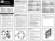
Method of installation of TV and FM aerial connection by using <strong>MK</strong> co-axial<br />
socket outlet and only one downlead.<br />
Conventional distribution system for TV and FM signals using a single aerial<br />
downlead.<br />
1<br />
2<br />
3<br />
4<br />
TV<br />
VID<br />
TV<br />
3<br />
FM<br />
4<br />
4<br />
TV DIST<br />
DAB<br />
1<br />
4<br />
TV<br />
TV<br />
VID<br />
SKY/DIG<br />
HI-FI<br />
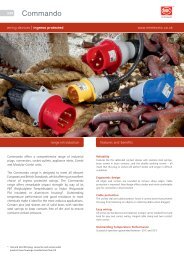
The signals from the TV and FM aerials and the satellite dish are<br />
combined together using two products. The first combines the TV and<br />
FM signals and the second adds the Sky signal to the TV/FM signal and<br />
provides a DC control path to power the LNB unit on the satellite dish.<br />
(These products are not supplied by <strong>MK</strong>).<br />
The single aerial down lead feeds into the triplexer (black lines in<br />
wiring diagram).<br />
The separated satellite signal is then fed to the decoder. The decoded<br />
satellite signal is then fed into the VCR along with the TV signal from<br />
the Triplexer. The output signal from the VCR then feeds into the TV<br />
and also back to the single outlet and onto the distribution amplifier<br />
(black lines in wiring diagram).<br />
The single cable back-feed then feeds back to the input of a multi way<br />
distribution amplifier, (typically located in the loft or garage) (red lines<br />
in wiring diagram).<br />
Each individual output from the distribution amplifier is then fed to<br />
the individual rooms in the house to a standard TV (single or diplexer)<br />
outlet to which the TV/VCR and/or Hi-Fi can be connected (blue lines<br />
in wiring diagram).<br />
2<br />
TV<br />
SAT 2<br />
SAT 1