Technical Specification - MK Electric
Technical Specification - MK Electric
Technical Specification - MK Electric

You also want an ePaper? Increase the reach of your titles
YUMPU automatically turns print PDFs into web optimized ePapers that Google loves.
Logic Plus <strong>Technical</strong><br />
technical hotline +44 (0)1268 563720 white | wiring devices<br />
Digital TV, Radio and Telephone Outlets<br />
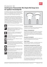
Dimensions (mm)<br />
1 gang (monobloc) dimensions (mm)<br />
86<br />
86<br />
86 33<br />
FM TV<br />
60.3<br />
2 gang (monobloc) dimensions (mm)<br />
FM TV<br />
SAT<br />
146 33<br />
120.6<br />
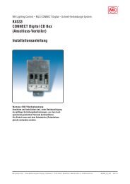
Installation<br />
● When installing the TV co-axial cable ensure<br />
that all cable bends are smooth so that the<br />
inner insulation is not crushed or squashed,<br />
otherwise the TV signal quality may be<br />
affected.<br />
● Not suitable for loop-in loop-out installations.<br />
● Use CT100 cable (or equivalent).<br />
Co-axial<br />
cable<br />
Co-axial<br />
cable<br />
TV Co-axial cable stripping details<br />
6.5 6.5<br />
Screening braid to remain in<br />
place over the inner insulation<br />
Earth terminal<br />
Earth<br />
terminal<br />
Clamping<br />
fixing screws<br />
Cable<br />
clamping<br />
plate<br />
Foil EMC<br />
screening<br />
gasket<br />
Clamping<br />
plate fixing<br />
screws<br />
Cable clamp<br />
View with cable<br />
clamp removed<br />
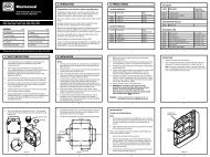
Telephone Outlet Connection<br />
Carefully strip 50mm of the Telephone cable<br />
outer sheath to expose the inner insulated<br />
conductors. Using the insertion tool supplied,<br />
(<strong>MK</strong> List no. 400NAT) carefully push each lead<br />
into the appropriate IDC terminals according to<br />
the wiring colour code stated in the BT Wiring<br />
Scheme diagram.<br />
Pins 1 and 6 are frequently unused, 4 wire cable<br />
may be used in these installations.<br />
If an existing installation uses a different wiring<br />
colour code system, this should be retained on<br />
any new or extended installation.<br />
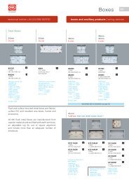
Additional secondary extension outlets should be<br />
wired in parallel with the existing installation via<br />
the IDC terminals, (i.e. pin 1 to pin1, pin 2 to pin<br />
2, etc).<br />
455<br />
In the event that the earth terminal is required to<br />
be used, the installer must ensure that a suitable<br />
earth conductor is present to connect to the earth<br />
terminal. (In the case of 2G products both TV<br />
modules should be earthed).<br />
In the event that the earth terminal is required to<br />
be used, the installer must ensure that a suitable<br />
earth conductor is present to connect to the earth<br />
terminal. (In the case of 2G products both TV<br />
modules should be earthed).<br />
Telephone Wiring Scheme<br />
1 GREEN / white<br />
2 BLUE / white<br />
3 ORANGE / white<br />
4 WHITE / orange<br />
5 WHITE / blue<br />
6 WHITE / green<br />
Note: Main wire colour is shown in capitals<br />
IDC<br />
terminals<br />
3 4<br />
2<br />
1<br />
First Socket Outlet<br />
Master<br />
1 2 3 4 5 6 1 2 3 4 5 6<br />
5<br />
6<br />
Cable Tie<br />
fixing point<br />
Cable tie<br />
Extension Outlet<br />
Secondary