DIRECTIONAL COUPLER ANALYSIS AS AN OPTICAL ... - ITS
DIRECTIONAL COUPLER ANALYSIS AS AN OPTICAL ... - ITS
DIRECTIONAL COUPLER ANALYSIS AS AN OPTICAL ... - ITS

Create successful ePaper yourself
Turn your PDF publications into a flip-book with our unique Google optimized e-Paper software.
J. Indones. Math. Soc. (MIHMI)<br />
Vol. xx, No. xx (20xx), pp. xx–xx.<br />
<strong>DIRECTIONAL</strong> <strong>COUPLER</strong> <strong><strong>AN</strong>ALYSIS</strong> <strong>AS</strong> <strong>AN</strong><br />
<strong>OPTICAL</strong> POWER TR<strong>AN</strong>SFER FOR TMoo<br />
MODE<br />
A. Rubiyanto, D. N. Widayanti, A. Y. Rohedi, Suryadi<br />
Abstract.<br />
The analysis of the optical power transfer in the linear step index directional-coupler<br />
based on the coupled-mode theory is inaccurate for a small gap. This problem has<br />
been previously overcome by using the normal-modes approximation. Generaly, this<br />
approximation has been solved by numerical methods such as Fourier transform or finite<br />
difference. In this paper, the Helmholtz equation is, instead, analytically solved by using<br />
a characteristic matrix of multilayer waveguides in order to find the electric field and its<br />
propagation constant of the normal-modes. Ti:LiNbO3 sistem, is used in the simulation<br />
which has a film of index (nf ) = 2,234, substrate material of index (ns) = 2,214, cover<br />
material of index (nk) = 1, and laser wavelength (λ) = 1,33 m. The result of simulation<br />
indicates that the relations between width gap (s), depth guide (d), width guide (h), and<br />
also coupling length (Lc) are non linear.<br />
1. INTRODUCTION<br />
The directional-couplers are the major interest in integrated optics, since it have<br />
potential applications in optical communications to be used as low-loss optical<br />
switches [1], high speed modulators [2], polarization splitter [3], integrated acoustooptical<br />
heterodyne interferometer[4] and wavelength demultiplexer/multi-plexer [4].<br />
Due to coupling effect, optical power can be transferred from one waveguide to<br />
Received dd-mm-yyyy, Accepted dd-mm-yyyy.<br />
2000 Mathematics Subject Classification: Applied Mathematics in Optics<br />
Key words and Phrases: optical power transfer, directional coupler,characteristic matrix of multilayer<br />
waveguides<br />
1
2 A. Rubiyanto et.al<br />
another adjacent waveguide as a result of the overlap in the evanescent fields of<br />
the two guides. The amount of power transferred between the waveguides depends<br />
upon the waveguide parameters, i.e, the guided wavelength, the confinement of the<br />
individual waveguides, the separation between them, the length over which they<br />
interact, and the phase mismatch between the individual waveguides [5]. The power<br />
transfer of two waveguides in the directional-couplers has been treated extensively<br />
utilizing the coupled-mode method, but as shown in [6] this method becomes less<br />
accurate when the waveguides get too close. An alternative choice is the normalmodes<br />
approximation. This approximation taken full account of the entire structure<br />
and solves for modal indices and guided fields of the supermodes. In the normalmodes<br />
approach, the characteristic of the directional-couplers are then represented<br />
by interferences between the guided fields of the supermodes [7], i.e symmetrical<br />
and asymmetrical modes. In practical, the directional-couplers are made in 3-D<br />
structure, consist of waveguides with finite lateral dimensions. In order to obtain<br />
the exact solutions of normal modes, the 3-D is usually reduced to 2-D guides<br />
structure [7],[8]. Hence in the 2-D guides, the two parallel waveguides with their<br />
surrounding medium can be considered as a single structure, so that the normalmodes<br />
of the such structure can be solved by method of multilayer waveguides. In<br />
this paper we use the multilayer waveguides to formulate the optical electric fields<br />
in the symmetrical directional-couplers. The expression of such the guided fields<br />
derived by method of multilayer waveguides given by Kogelnik [9], and Rohedi [10].<br />
2. MULTILAYER WAVEGUIDES<br />
The fundamental component of the integrated optics is optical waveguide.<br />
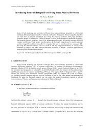
The simplest optical waveguide is the planar slab guide shown in Fig 1, where a<br />
planar film of refractive index nf is sandwiched between a substrate and a cover<br />
material with lower refractive indices ns and nc (nf ≥ns ≥nc). The structure of a<br />
multilayer waveguide structure and its coordinate system are shown in Fig.1. The<br />
direction of propagation is in the z direction, while the variation of the media is<br />
in the x direction. For simplicity the structure is assumed to be one dimensional<br />
and lossless. Basically the multilayer waveguide can be considered as three-layer<br />
guides, of which a stack consists of N layers with parallel boundaries is sandwiched<br />
between a substrate and a cover material. According to<br />
∂ 2 Hyi<br />
∂x 2 − γ2 i Hyi = 0, i = s, f, c (1)<br />
where γc (propagation constant at cover), κf (film layer), and γs(substrate layer)<br />
define as:<br />
−γ 2 c = n 2 ck 2 o − β 2 , κ 2 f = n 2 f k 2 o − β 2 , −γ 2 s = n 2 sk 2 o − β 2<br />
(2)<br />
hereinafter conducted by applying of boundary condition to Hy representing mathematical<br />
solution from equation(1-2) and continuity Ez , successively at x=d/2 and<br />
x=-d/2, where at second of the x are Hyc = Hk and Hys = Hs. So that transversal<br />
component of the magnetic field which propagate in third layer can be writed as:<br />
Hyc = Hce −γc(x−d/2) , x > d/2 (3)
Y<br />
X<br />
d/2<br />
-d/2<br />
cover, n c<br />
film, n f<br />
Directional Coupler Analysis 3<br />
substrate, n s<br />
Figure 1: The geometry of single optical waveguide<br />
Hyf = Hf cos(κf (x − d/2) + φk), d/2 < x < d/2 (4)<br />
Hyf = (−1) m Hf cos(κf (x + d/2) + φk), d/2 < x < d/2 (5)<br />
Hys = Hse −γk(x−d/2) , x < d/2 (6)<br />
where Hc, Hf and Hs are the amplitude of transverse component of magnetic field<br />
at third layer. While φc and φs are respectively given by:<br />
tanφc = (n 2 f /n 2 c)(γc/κf ) (7)<br />
tanφs = (n 2 f /n 2 c)(γs/κf ) (8)<br />
The normalization of magnetic field guided in equation (6-8):<br />
Hy =<br />
⎧<br />
⎨<br />
⎩<br />
Hf cos(φk)e −γc(x−d/2) :<br />
(−1) m Hf cos(κf (x + d/2) − φs) :<br />
Hf cos(φc)e −γs(x−d/2) :<br />
By applying of boundary condition at parallel field with the boundary area that is<br />
Hy and ∂Hy<br />
∂x to equation(6-9), hence the dispertion relationship for the TM mode<br />
is given in the form:<br />
2κf d − 2φs − 2φk = 2mπ (10)<br />
where m = 0,1,2,3, are order of modes. Form the normalization from relation<br />
dispersion for the TM mode:<br />
�<br />
√qs<br />
V<br />
nf<br />
ns<br />
�<br />
√<br />
1 − b = mπ + tan −1<br />
� �<br />
b<br />
b + a(1 − bc)<br />
+ tan−1<br />
1 − b 1 − b<br />
Z<br />
(9)<br />
(11)
4 A. Rubiyanto et.al<br />
With the normalized frequency, V:<br />
�<br />
V = kod<br />
n 2 f − n2 s<br />
The normalized effective refractive index, b:<br />
�<br />
N<br />
b =<br />
2 − n2 s<br />
n2 f − n2 � �<br />
2 nf s n2 �<br />
sqs<br />
where N is effective refractive index. The reduce factor, qs given by:<br />
qs =<br />
N 2<br />
n 2 f<br />
+ N 2<br />
n 2 f<br />
n 2 s/n 2 f<br />
− 1 =<br />
(1 − b) + bn4 s/n4 f<br />
While assymetricity factor of refractive index at cover and substrate layer, a is<br />
given by:<br />
a = n4 f<br />
n4 n<br />
k<br />
2 s − n2 k<br />
n2 f − n2 (15)<br />
s<br />
The factor C is defined as:<br />
c =<br />
�<br />
1 − n2 s<br />
n 2 f<br />
� �<br />
1 − n2 k<br />
n 2 f<br />
3 <strong>DIRECTIONAL</strong> <strong>COUPLER</strong><br />
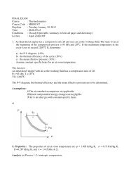
The geometrical structure of directional coupler is shown in Fig. 2 with s is gap<br />
distance betwen the waveguides, h is width of each canal along as the lateral direction,<br />
d is deepth of each canal, and Z is interaction length of the two waveguide.<br />
The deepth and width of each canal have been designed such that each guide only<br />
support single guide mode. The transfer of optical energy can be explained by using<br />
the coupled mode theory. Based on this theory if the gap distance is big enough,<br />
hence elementary evanescent field from second of canal (symbolised by A and B)<br />
alongside gap area do not generate the coupling, so that at each a optical wave<br />
at the basic mode can propagate individually. On the contrary if the distance of<br />
betwen canal very small hence evanescent field alongside is giving each other and<br />
coupling on the way of propagation:<br />
∂A(z)<br />
∂z<br />
∂B(z)<br />
∂z<br />
�<br />
= −jκABB(z)e −(βB−βA)z<br />
= −jκBAA(z)e (βB−βA)z<br />
(12)<br />
(13)<br />
(14)<br />
(16)<br />
(17)<br />
(18)
n s<br />
n c<br />
Directional Coupler Analysis 5<br />
n f1<br />
n f2<br />
Figure 2: Directional coupler optical wave guide<br />
where κAB = κAB = κ coupling coefficient. A(z) and B(z) are defined as:<br />
A(z) = Ae −jγz e −j∆z<br />
B(z) = Be −jγz e −j∆z<br />
where ∆ = βB−βA<br />
2 is the phase missmatch. Equation (21) substitution by equation<br />
(23-24) and wrote:<br />
A = κB<br />
(21)<br />
γ + ∆<br />
Equation (21) substitution by equation (22-23) and resulted:<br />
B = κA<br />
γ − ∆<br />
Solution from equation (21-22) are:<br />
�<br />
A(z) = Ase −j√κ2 +∆2z + Aae −j√κ2 +∆2z �<br />
e −j∆z<br />
with, Bs =<br />
B(z) =<br />
κAs √ , Ba =<br />
κ2 +∆2−∆ �<br />
Bse −j√ κ 2 +∆ 2 z + Base −j√ κ 2 +∆ 2 z �<br />
e −j∆z<br />
κAa<br />
√ κ 2 −∆ 2 +∆<br />
Optical energy transfer between the canal in the directional coupler became<br />
by the coupling distance ( Lc), which is defined as:<br />
where ∆β = βs − βa<br />
Lc = φ<br />
∆β orLc = φ<br />
2κ<br />
(19)<br />
(20)<br />
(22)<br />
(23)<br />
(24)<br />
(25)
6 A. Rubiyanto et.al<br />
4. CHARACTERISTICS MATRIX METHOD<br />
Charactristic Matrix Method is method which aim to determine β and Hy of<br />
Helmholtz equation, equation(1). The formulation of the matrix characteristic at<br />
each layer for the TM Mode are symbolising tangensial field as:<br />
U(x) = Hy<br />
V (x) = − j<br />
n2 ∂U j<br />
= −<br />
∂x n2 ∂Hy j<br />
= − ωɛoEz<br />
(27)<br />
∂x n2 Equation of the propagation of optical wave for TM Mode in the film layer:<br />
Equation (32) above having solution:<br />
(26)<br />
∂ 2 U<br />
∂x 2 + κ2 U = 0 (28)<br />
U = Ae −jκx + Be jκx<br />
V = − j<br />
n2 ∂U κ<br />
=<br />
∂x n2 �<br />
−Ae (−jκx) + Be (jκx)�<br />
(30)<br />
Hence U and V can be expressed in the form of matrix multiplication and vector<br />
column: �<br />
U<br />
V<br />
� �<br />
e<br />
=<br />
−jκx e−jκx − κ<br />
n2 −jκx e κ<br />
n2 ejκx � �<br />
A<br />
B<br />
�<br />
(31)<br />
If at the first layer that is at the area xo ≤≤ x1, specified by U(x = xo) = Uo and<br />
V (x = xo) = Vo, hence equation (34) becoming:<br />
�<br />
Uo<br />
Vo<br />
� �<br />
e<br />
=<br />
−jκx e−jκx − κ<br />
n2 −jκx e κ<br />
n2 ejκx � �<br />
A<br />
B<br />
�<br />
(32)<br />
�<br />
A<br />
So that<br />
B<br />
�<br />
can be expressed as:<br />
� �<br />
=<br />
1<br />
2ejκxo − n2<br />
2κ ejκxo<br />
� �<br />
Uo<br />
�<br />
(33)<br />
� A<br />
B<br />
From equation (36) got:<br />
− 1<br />
2 e−jκx<br />
n2<br />
2κ ejκxo<br />
Vo<br />
(29)<br />
A = 1<br />
�<br />
Uo −<br />
2<br />
n2<br />
κ Vo<br />
�<br />
e jκxo (34)<br />
B = 1<br />
�<br />
Uo +<br />
2<br />
n2<br />
κ Vo<br />
�<br />
e −jκxo (35)<br />
Equation (37-38) are substituted into equation(32-33):<br />
U = Uocos(κ(x − xo)) + j n2<br />
κ Vosin(κ(x − xo)) (36)
Directional Coupler Analysis 7<br />
V = +j n2<br />
κ Uosin(κ(x − xo)) + Vocos(κ(x − xo)) (37)<br />
If expressed in the form of the matrix multiplication and vector column become:<br />
� U<br />
V<br />
� �<br />
=<br />
cos(κ(x − xo) j n2<br />
κ sin(κ(x − xo))<br />
j n2<br />
κ sin(κ(x − xo)) cos(κ(x − xo)<br />
� � Uo<br />
At the nth layer, x = xn, κ = κn U(x = xm) = Un and V (x = xn) = Vn got:<br />
�<br />
Un<br />
Vn<br />
� �<br />
cos(κn(xn − xn−1)<br />
=<br />
j n2<br />
κn sin(κn(xn<br />
j<br />
− xn−1))<br />
κn<br />
n2 sin(κn(xn − xn−1)) cos(κn(xn − xn−1))<br />
� �<br />
Un−1<br />
Vn−1<br />
�<br />
If the width of each layer hi = xi − xi−1, that way also propagation constan of<br />
layer: κi = � k2 on2 i − β2 by i = 1,2,3,,n. So that the matrix form in general:<br />
� � � �<br />
Ui Ui−1<br />
(40)<br />
Vi<br />
= Mi<br />
Vi−1<br />
Mi express the characteristic matrix to each layer i-th from film layer optical guide<br />
, that is:<br />
�<br />
cos(κihi) j<br />
Mi =<br />
n2<br />
κi sin(κihi)<br />
j κi<br />
n2 �<br />
(41)<br />
sin(κihi) cos(κihi)<br />
Thereby vector of the tangensial � �field<br />
tangensial � � at the area of boundary substrat-<br />
Uo Un<br />
film and film-kover that is and can be connected due to<br />
By matrik M =<br />
Vo Vn<br />
�<br />
Un<br />
Vn<br />
�<br />
�<br />
Uo<br />
= MnMn−12M1<br />
Vo<br />
�<br />
�<br />
m11 m12<br />
�<br />
m21 m22<br />
=<br />
� m11 m12<br />
m21 m22<br />
� � Uo<br />
Vo<br />
Vo<br />
�<br />
�<br />
(38)<br />
(39)<br />
(42)<br />
is referred as the multi layer matrix characteristic.<br />
The result of above formulation indicate that if each layer by the multi layer matrix<br />
characteristic, hence all area of the film s] also deputized by the multi layer matrix<br />
characteristic whicah are representing multiplication from all matrix characteristic<br />
in each layer alongside film area. To get the equation of the dispersion relationship<br />
of the planar wave guide for the TM Mode, in the firs it is originally evaluated by<br />
the electrics field and magnetic field which are tangensial alongside the substrat<br />
area, that is at x = xo, what is the in form of:<br />
Us = Bse γs(x−xo)<br />
Vs = − j<br />
n2 γsBse<br />
s<br />
γs(x−xo)<br />
and alongside the cover area, that is at xn<br />
Uk = Ake γk(x−xn)<br />
(43)<br />
(44)<br />
(45)
8 A. Rubiyanto et.al<br />
Vk = − j<br />
n2 γkBse<br />
k<br />
γk(x−xn)<br />
(46)<br />
By applying the continuity condition of tangensial field at the boundary area<br />
substrate-film, at x=xo, and also at x=xn found:<br />
Uo = Us = Bs<br />
Vo = Vs = −j γs<br />
n2 Bs<br />
s<br />
Un = Uk = Bk<br />
Vn = Vk = −j γk Bk<br />
If the value Uo, Vo, Un and Vn included into equation (45) found by the relation:<br />
n2 k<br />
Ak = m11Bs − j γs<br />
n2 Bs<br />
s<br />
j γk<br />
n2 Ak = m21Bs − j γs<br />
n2 m22Bs<br />
s<br />
k<br />
By elimination of Ak and Bs from equation (52), hence found by the equation of<br />
dispersion relationship for the optical wave of TM mode:<br />
�<br />
�<br />
γk γs γsγk<br />
j<br />
− m21 = 0 (50)<br />
m11<br />
n2 + m22<br />
k n2 s<br />
+ m12<br />
n2 sn2 k<br />
5. RESULT <strong>AN</strong>D DISCUSSION<br />
5.1 The Accuration test of Matrix characteristics Method at the<br />
Normatization of Effective Refractive Index b as Function of Normalization<br />
Frequency V<br />
To test the accuracy of method of matrik characteristic, hence it have previously<br />
conducted by comparison of the result with the analytical method, by taking<br />
simple example that is effective refractive index relation normalization, b and normalization<br />
frequency, V and also the pattern of magnetic field at guide of wave slab.<br />
An analytically by using equation(13) knowable to hence assess the b of guide of<br />
wave slab, beforehand determine the value nfs, V, m and a. By γk ( propagation<br />
constan of optic wave as long as cover layer),κf ( layer film) and γs( substrate layer)<br />
defined [10]: γk = V √<br />
qsnks 1<br />
�<br />
b + a(1 − bc),<br />
κf = V<br />
d<br />
√ qsnfs<br />
d<br />
� 1 − b), γs = V<br />
nfk<br />
√<br />
d<br />
qs<br />
where nfs represent the comparison of refractive index film-substrate, what<br />
its value have to be bigger than 1, where at this calculation is taken by nfs = 1,01.<br />
From equation (18) found by value nfk, that is comparison of film-cover refractive<br />
(47)<br />
(48)<br />
(49)
Directional Coupler Analysis 9<br />
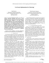
Figure 3: Relationship of dispersi normalization of a guide of wave of moda TM to<br />
three order<br />
�<br />
�<br />
�<br />
�<br />
index equal to: nfk = �<br />
�<br />
−1+<br />
�<br />
�<br />
2a 1− 1<br />
�<br />
nfs � � �<br />
1<br />
1<br />
1+4a n −4a<br />
fs<br />
nfs While nks is comparison of refractive index kover-substrate which defined as:<br />
nks = nfs<br />
nfk<br />
Later the magnitude of b is obtained from compared betwen the analytical method<br />
and the method of matrix characteristic, equation (53), as shown in Table 1.<br />
Table 1. The calculation of effective refractive index with the<br />
analytical method and matrik of characteristic<br />
m V a b1 banalitic b1 bmatrix<br />
0 2 0 0,9 0,4577 0,9 0,4577<br />
4 0 0,9 0,7397 0,9 0,7397<br />
6 0 0,9 0,8516 0,9 0,8516<br />
8 0 0,9 0,9047 0,9 0,9047<br />
10 0 0,9 0,9338 0,9 0,9338<br />
1 6 0 0,9 0,4294 0,4 0,4294<br />
8 0 0,9 0,6244 0,5 0,6244<br />
10 0 0,9 0,7368 0,7 0,7368<br />
2 8 0 0,9 0,1961 0,3 0,1961<br />
10 0 0,9 0,4183 0,3 0,4183<br />
�
10 A. Rubiyanto et.al<br />
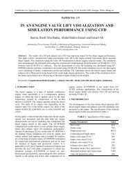
Figure 4: Visualizing the wave propagation at directional coupler in s= 1µm.<br />
The equation of dispersion relationship for the optical wave TM mode can be expressed<br />
alongside guide the wave planarin the form of the curve of between V and<br />
b, either through analytical and also matrix characteristic, what its result is shown<br />
at Fig. 3.<br />
5.2 Pattern of magnetic field at directional coupler<br />
The theory has been test for a structure consisting of two parallel slab guides<br />
d = 2µm wide each, separated by a distance of h = 3µm. Typical values for<br />
refractive indexes of LiNbO3 and T i : LiNbO3 have been chosen for substrate and<br />
guides, respectively. A numerical computation has been carried wide for each guide<br />
with an index 2,201, surronded by a medium with an index of 2,2, the illumination<br />
resulting is shown in Fig. 4.<br />
The pattern of magnetic field at z=0 and also seen the propagation of the<br />
wave which is couple into canal 1 that shown in above Figure. Then the optical<br />
wave transfer to the other canal as long as direction of z. The power carried by these<br />
structures is found to periodically exchange between them with distance. According<br />
to normal-mode approximation, coupling length i.e the distance requried for the<br />
exchange power has been transferred to the opposite waveguide is defined as Lc. In<br />
Figure 5 it is shwon that progressively increase width gap (s) hence coupling length<br />
(Lc) also progressively growing larger.<br />
It can be explaned if the width gap (s) increase, so that the effective of contant<br />
propagation of asimetri mode,βa progressively come near the effective value of<br />
propagation symmetry mode. At wide of big gap that is s ≥ 4µman effective value<br />
propagation constant is equal, so that ∆β = 0, as a result assess the Lc very big.<br />
Explainable the mentioned by using theory of the mutually couple mode. Based on
Directional Coupler Analysis 11<br />
Figure 5: Relation width gap s with coupling length (Lc) for variable of h<br />
this theory when the wide of each gap of canal very small, hence elementary wave<br />
evanescent moda alongside the gap area is giving each other perturbation, coupling<br />
betwem both causing the amplitude of optical wave which propagate at each canal<br />
change as long as distance its propagation. On the contrary if the width of gap<br />
is big enough, hence elementary wave evanescent moda from both canal alongside<br />
gap area do not generate the coupling, because of there no binding evanescent from<br />
optic wave which transmission into canal 1 tired of canal 2, so that at each canal<br />
of optic wave at the elementary moda can propagate individually.<br />
Variation of the deepness, d is also influence the coupling length ( Lc), where<br />
progressively increase the d hence Lc also progressively growing larger. Explainable<br />
the mentioned as follows, that progressively increase [it] deepness hence bind the<br />
laser ray which transmission also progressively increase a lot of so that the energi<br />
laser ever greater also. With the existence of energi laser which progressively growing<br />
larger, hence energy of optic wave at canal one can make a move to canal two,<br />
longly is ever greater coupling (see Figure 6).<br />
Wide Variation of the lateral (h), h also influence the coupling length (Lc),<br />
where progressively increase the h hence Lc also progressively growing larger. Explainable<br />
[the] mentioned as that happened [at] deepness accretion, d, that progressively<br />
increase wide [it] lateral, h hence bind the laser ray which transmission<br />
also progressively increase so that energi laser also progressively growing larger.<br />
With the existence of energi laser which progressively growing larger, hence energy<br />
of optic wave [of] [at] canal. one can make a move to canal two, longly [is] ever<br />
greater coupling.
12 A. Rubiyanto et.al<br />
Figure 6: Relation width gap s with coupling length (Lc) for variable of d<br />
Figure 7: Relation width gap s with coupling length (Lc) for variable of h
Directional Coupler Analysis 13<br />
6. CONCLUSION.<br />
The result of simulation indicate that the incresing of width gap (s), depth guide<br />
(d), width guide (h), hence apart at the timeof the happening of energy transfer<br />
betwen the canal as long of coupling, Lc also progressively growing larger.<br />
Acknowledgement. We would like to thanks for Dr. Andonowati for valuable<br />
discussion during in the EU Final Project Meeting in ITB.<br />
REFERENCES<br />
1. R.C.Alferness, “Guided-wave devices for optical communications”, IEEE Journal<br />
Quantum Electronic, QE-17 (1981)<br />
2. P. Danielsen, “Two Dimensional Propagating Beam Analysis of an Electrooptic<br />
Waveguide Modulator”, IEEE Journal Quantum Electronic, Vol.QF-20, No.9, (1984)<br />
3. A. N.Miliou, R.Srivastava, and R.V.Ramasvamy, “A1,3 Directional-coupler Polarization<br />
Splitter by Ion Exchanged”, Journal of Lightwave Technology, Vol.11, No.2,<br />
(1993)<br />
4. A. Rubiyanto. R. Ricken. H. Herrmann, and W. Sohler, “Integrated Optical<br />
Heterodyne Interferometer in Lithium Niobate”, Journal Non Linear Optic and<br />
Materials, (1993)201-206<br />
5. R.Y. Ternoven, S. Honkamen, and S.I. Najafi, “Analysis of Symetrical Directionalcoupler<br />
and Asymetric Mach-Zehnder Interferometer as 1,3µm and 1,5µm Dual Wavelength<br />
Demultiplexer/Multiplexer”, Journal Non Linear Optic and Materials, (1993)201-<br />
206<br />
6. T. Tamir, Theory of Optical Waveguides in Guide Wave Optoelectronics, 2nd edition,<br />
springer-verlag, New York, 1990.<br />
7. E. Marom et al, “Relation Between Normal-modes and Coupled-Modes Analyses of<br />
Parallel Waveguides”, Journal Of Qantum Electronics,Vol.QE-20 ,No.11 (1984)<br />
8. K.Chiang, “Dual Effective index method the analysisof rectanguler waveguides”, Applied<br />
Optic,Vol 25 , (1986)<br />
9. H. Kogelnik, Theory of Optical Waveguides in Guide Wave Optoelectronics, Editor<br />
Theodor Tamir, 2nd edition, springer-verlag, New York,1990<br />
10. A.Y. Rohedi, Z. Arifin, A. Rubiyanto, “Calculating approximate for the propagation<br />
constant of Optical Waveguides Using Multilayer Characteristic Matrix”, Prosceeding<br />
of Aplied Physics, Physics Departement, Institut Teknologi Sepuluh Nopember(1984)<br />
11. L.M. Walpita, “Solutions for Planar Optical Waveguide Equations by Selecting Zero<br />
Elements in a Characteristic matrix”, Opt.Soc.Am, Vol.2 (1985)
14 A. Rubiyanto et.al<br />
12. S. L. Lee, “Explicit Formulas of Normalized Radiation Modes in Multilayer Waveguides”,<br />
Journal of Lightwaves of Technology, Vol.12, No.12 (1994)<br />
13. S. Nakamura, Applied Numerical Methods With Software, Prentice Hall, New York,<br />
1990.<br />
A. Rubiyanto, D. N. Widayanti, A. Y. Rohedi, Suryadi: Department of Physics,<br />
Institut Teknologi Sepuluh Nopember, Surabaya 60111, Indonesia.<br />
E-mail: arubi@physics.its.ac.id