ZX Computings - OpenLibra
ZX Computings - OpenLibra
ZX Computings - OpenLibra

You also want an ePaper? Increase the reach of your titles
YUMPU automatically turns print PDFs into web optimized ePapers that Google loves.
which the keyboard symbols<br />
can be written. Eleven keys are<br />
required, as the numbers 0-9<br />
are not a lot of use if you cannot<br />
RUBOUT any mistakes, except<br />
by going back to the<br />
Sinclair keyboard. The<br />
RUBOUT key* requires the<br />
pressing of two keys together,<br />
0 and SHIFT. Therefore the<br />
SHIFT key must be included on<br />
the numeric pad. Pressing the<br />
SHIFT key on its own does<br />
nothing, so hitting it accidentally<br />
does not give an error on<br />
INPUT.<br />
Having the SHIFT key on<br />
the numeric pad also means<br />
that all the cursor moving keys<br />
are also available, SHIFT 5(*4,<br />
SHIFT 6{ f }, SHIFT 7( I ) and<br />
SHIFT 8(-H. These can be used<br />
to quickly EDIT programs,<br />
along with the EDIT key which<br />
is SHIFT 1. As all of these keys<br />
can be reached with one hand<br />
if they are grouped in a square,<br />
it means the other hand is free<br />
to do other things, such as<br />
follow a program in a book or a<br />
set of data to be INPUT. This<br />
can be very useful, as it is easy<br />
to lose one's place when trying<br />
to watch the screen and the<br />
written program at the same<br />
time.<br />
As the keys 1-5, 6-0 and<br />
SHIFT are all on different address<br />
lines, all three must be<br />
included on the numeric<br />
keypad. These are A8 (SHIFT),<br />
A11 (1-5) and A12(6-0). We<br />
also need ALL of the<br />
(K)EY(B)OARD-(D)ATA lines<br />
(inputs to the computer)<br />
KBDO-KBD4.<br />
The keyboard port KBD0-4<br />
is addressed by the <strong>ZX</strong>81<br />
ROM as INPUT PORT 254 (FE<br />
in HEXADECIMAL). BUT<br />
because of the way Sinclair addresses<br />
his ports, the keyboard<br />
port appears at every EVEN IN-<br />
PUT PORT address. That is<br />
when address line AO is at<br />
Binary 0, the IOREQ and the<br />
WR are Binary 0.<br />
The upper eight address<br />
lines (A8-A1 5) reflect what was<br />
in the B register at the time of<br />
calling for an input from the<br />
port. So the setting of a bit in<br />
the "B" register to Binary 0 addresses<br />
that key (the address<br />
tine to 0 volts) and then looks at<br />
the result on the data lines.<br />
When a key is pressed, the appropriate<br />
data line will also be<br />
Binary 0.<br />
These actions are all done<br />
by the BASIC ROM when using<br />
INPUT or INKEY$. This information<br />
has only been included<br />
for the machine code programmer.<br />
We must open up the casing<br />
of the <strong>ZX</strong>81 to get at the<br />
connections on the printed circuit<br />
board inside, and thereby<br />
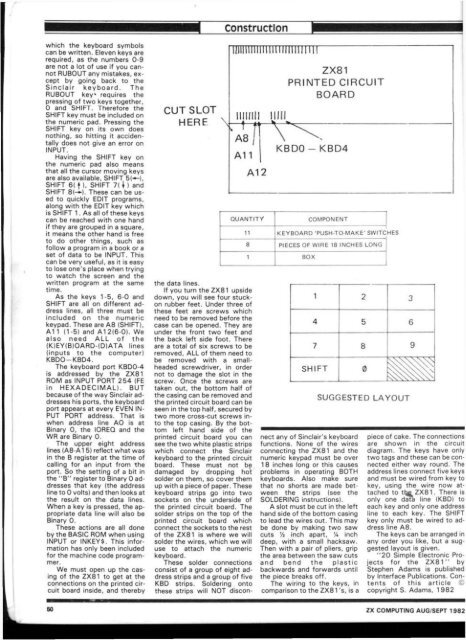
CUT SLOT<br />
HERF \<br />
Construction<br />
uiiiiniiiiiiii iiiiuii] 11!<br />
" t 7<br />
A8 I<br />
A 1 1<br />
the data lines.<br />
If you turn the <strong>ZX</strong>81 upside<br />
down, you will see four stuckon<br />
rubber feet. Under three of<br />
these feet are screws which<br />
need to be removed before the<br />
case can be opened. They are<br />
under the front two feet and<br />
the back left side foot. There<br />
are a total of six screws to be<br />
removed, ALL of them need to<br />
be removed with a smallheaded<br />
screwdriver, in order<br />
not to damage the slot in the<br />
screw. Once the screws are<br />
taken out, the bottom half of<br />
the casing can be removed and<br />
the printed circuit board can be<br />
seen in the top half, secured by<br />
two more cross-cut screws in*<br />
to the top casing. By the bottom<br />
left hand side of the<br />
printed circuit board you can<br />
see the two white plastic strips<br />
which connect the Sinclair<br />
keyboard to the printed circuit<br />
board. These must not be<br />
damaged by dropping hot<br />
solder on them, so cover them<br />
up with a piece of paper. These<br />
keyboard strips go into two<br />
sockets on the underside of<br />
the printed circuit board. The<br />
solder strips on the top of the<br />
printed circuit board which<br />
connect the sockets to the rest<br />
of the <strong>ZX</strong>81 is where we will<br />
solder the wires, which we will<br />
use to attach the numeric<br />
keyboard.<br />
These solder connections<br />
consist of a group of eight address<br />
strips and a group of five<br />
KBD strips. Soldering onto<br />
these strips will NOT discon-<br />
A12<br />
<strong>ZX</strong>81<br />
PRINTED CIRCUIT<br />
BOARD<br />
KBDO - KBD4<br />
QUANTITY COMPONENT<br />
11 KEYBOARD 'PUSH-TO-MAKE' SW1TC HES<br />
8 PIECES OF WIRE 18 INCHES LONG<br />
1 BOX<br />
1 2 3<br />
4 5 6<br />
7 8 9<br />
SHIFT 0<br />
nect any of Sinclair's keyboard<br />
functions. None of the wires<br />
connecting the <strong>ZX</strong>81 and the<br />
numeric keypad must be over<br />
1 8 inches long or this causes<br />
problems in operating BOTH<br />
keyboards. Also make sure<br />
that no shorts are made between<br />
the strips (see the<br />
SOLDERING instructions).<br />
A slot must be cut in the left<br />
hand side of the bottom casing<br />
to lead the wires out. This may<br />
be done by making two saw<br />
cuts Vi inch apart, % inch<br />
deep, with a small hacksaw.<br />
Then with a pair of pliers, grip<br />
the area between the saw cuts<br />
and bend the plastic<br />
backwards and forwards until<br />
the piece breaks off.<br />
The wiring to the keys, in<br />
comparison to the <strong>ZX</strong>81 's, is a<br />
SUGGESTED LAYOUT<br />
piece of cake. The connections<br />
are shown in the circuit<br />
diagram. The keys have only<br />
two tags and these can be connected<br />
either way round. The<br />
address lines connect five keys<br />
and must be wired from key to<br />
key, using the wire now attached<br />
to ttj^<strong>ZX</strong>81. There is<br />
only one data line (KBD) to<br />
each key and only one address<br />
line to each key. The SHIFT<br />
key only must be wired to address<br />
line A8.<br />
The keys can be arranged in<br />
any order you like, but a suggested<br />
layout is given.<br />
"20 Simple Electronic Projects<br />
for the <strong>ZX</strong>81" by<br />
Stephen Adams is published<br />
by Interface Publications. Contents<br />
of this article ©<br />
copyright S. Adams, 1982<br />
GO <strong>ZX</strong> COMPUTING AUG/SEPT 1982