B+W Baureihe MA e - Rohr Armaturen AG
B+W Baureihe MA e - Rohr Armaturen AG
B+W Baureihe MA e - Rohr Armaturen AG

Create successful ePaper yourself
Turn your PDF publications into a flip-book with our unique Google optimized e-Paper software.
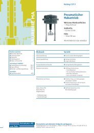
Pneumatic stroke<br />
actuator<br />
Diaphragm effetive areas<br />
– 70 to 1070 cm 2<br />
Shut off forces<br />
– 0.5 to 122 kN<br />
Strokes<br />
– 10 to 140 mm<br />
Allowable airpressure<br />
up to 6 bar<br />
von <strong>Rohr</strong><br />
<strong>MA</strong>-SERIES<br />
<strong>Armaturen</strong> <strong>AG</strong><br />
C211.1/<strong>MA</strong>.7<br />
Operating and<br />
maintenance instructions<br />
Pneumatische und elektrische Stellgeräte und Apparate<br />
Fichtenhagstrasse 4, CH-4132 Muttenz 2, Telefon +41 (0) 61 461 48 48, Fax +41 (0) 61 461 18 27<br />
e-mail: info@von-rohr.ch, www.von-rohr.ch
Operating and maintenance instructions<br />
1. Warning symbols 3<br />
2. Safety advices 3<br />
3. Qualified personnel 3<br />
I. Description 4<br />
1.1 Introduction 4<br />
1.2 Specification (drawing and bill of materials) 4<br />
II. Mounting to valve 4<br />
1. Preparation and measures of precaution 4<br />
2. Mounting 4<br />
3. Mounting Po actuators 4<br />
4. Mounting Ps actuators 5<br />
III. Assembly instructions 6<br />
1. Disassemble Po actuators 6<br />
2. Assemble Po actuators 6<br />
3. Disassemble Ps actuators 7<br />
4. Assemble Ps actuators 8<br />
IV. Maintenance 9<br />
1. General indications 9<br />
V. Specifications 10<br />
VI. Spare parts offer / orders 12
C211.1/<strong>MA</strong>.7<br />
1. Warning symbols<br />
Safety advices and warnings are made for preventing danger against life and health of users and maintenance<br />
personnel resp. preventing material damage.They are being stressed by the presently described signal<br />
terms and in addition marked with warning symbols (pictograms). The applied symbols have the following<br />
meanings:<br />
Danger: Death, severe injury and/or significant material damage will be the consequence, if the<br />
appropriate precautions should not be taken.<br />
Warning: Death, severe injury and/or significant material damage may be the consequence, if the<br />
appropriate precautions should not be taken.<br />
Caution: Light injury and/or material damage may be the consequence, if the appropriate precautions<br />
should not be taken.<br />
Note: Important information about the product itself, about how to handle the product, to which<br />
special attention is being called.<br />
2. Safety advices<br />
The actuator has been exclusively designed for the use according to the specification in our order confirmation.<br />
Any other use is not according to the directives. For resulting damages the user alone is liable.<br />
Unauthorized changes, as well as the use of non original von <strong>Rohr</strong> spare parts exclude any responsibility<br />
for damages caused. Any change brought to the installation is done at the users own risk.<br />
Maintenance and repair operation may only be done by qualified personnel observing the respective<br />
directives.<br />
Actuators bring up great actuating power. Assembly and initiation are to be done under strict observation<br />
of the safety instructions.<br />
It is expressively pointed out to follow the instructions for explosive devices where appropriate.<br />
The following instructions are to be observed before any maintenance operations:<br />
� Depressurize the conduit.<br />
� Exclude initiation by third party.<br />
3. Qualified personnel<br />
According to the spirit of this manual, such persons are familiar with assembly, initiation and operation<br />
of this product, and have the qualifications for executing their function, like:<br />
� Training or instruction according to the actual standards in safety features maintaining and using<br />
appropriate safety equipments.<br />
� Training in first aid.<br />
� Training resp. permission to perform tasks with explosive devices.<br />
� Training at von <strong>Rohr</strong> <strong>Armaturen</strong> <strong>AG</strong>, CH-4132 Muttenz.<br />
3
4<br />
Operating and maintenance instructions<br />
I. Description<br />
1.1 Introduction<br />
The purpose of this manual is to make yourself familiar with design, function and maintenance. Please read<br />
this manual thoroughly in order to be able to operate the actuator effectively and obtain a long life time.<br />
1.2 Specification (drawing and bill of materials)<br />
See pages 10 to 12.<br />
II. Mounting to valve<br />
1. Preparation and measures of precaution<br />
The concept development of the actuator and the choice of materials are done according to the specification<br />
of the order. Application conditions diverging from the ordering designations are to be allowed<br />
by the manufacturer.<br />
2. Mounting<br />
The actuator may be mounted on valves and other devices of various types of construction. Suitable mounting<br />
parts are usually provided with the actuator.Typically, the actuator is mounted upright onto the valve.<br />
Caution: Do not turn the stem when in closed position!<br />
3. Mounting Po actuators<br />
� Apply pressure on the actuator until the stem is drawn in.<br />
� Screw the actuator coupling onto the actuator stem.<br />
� Put the actuator on the valve – the pillar threads go into the holes of the traverse.<br />
� Screw on the pillar nuts – tighten with 80 Nm.<br />
� Depressurize the actuator – make sure the valve stem is at the bottom.<br />
� Set the actuator coupling in a way that it fits upon the valve coupling.<br />
� Set the pressure in the actuator above the minimal positioning pressure, and verify the nominal<br />
stroke with a measuring stick or a calliper (space between actuator and valve coupling) –<br />
distort actuator coupling if required.<br />
� Screw the couplings together loosely, go through the stroke, position the couplings appropriately.<br />
� Screw the couplings together tightly in central position.<br />
� Tighten the counternut above the actuator coupling.
C211.1/<strong>MA</strong>.7<br />
4. Mounting Ps actuators<br />
� Screw the actuator coupling onto the actuator stem.<br />
� Put the actuator on the valve – the pillar threads go into the holes of the traverse –<br />
make sure the valve stem is at the bottom.<br />
� Screw on the pillar nuts – tighten with 80 Nm.<br />
� Position the actuator coupling in a way that the distance to the valve coupling corresponds<br />
to the nominal stroke – verify with a measuring stick or a calliper.<br />
� Set the pressure in the actuator to the upper range.<br />
� Stroke with loose connected couplings and adjust couplings.<br />
� Screw the couplings together tightly in middle position.<br />
� Tighten the counternut above the actuator coupling.<br />
5
6<br />
Operating and maintenance instructions<br />
III. Assembly instructions<br />
The actuators of type series <strong>MA</strong> are assembled and disassembled within special appliances in the factory.The<br />
following assembly instructions are based upon simpler utilities.They are meant for working on existing actuators<br />
installed at the user’s location.Table 2 shows a list of utilities which can be purchased.<br />
1. Disassemble Po actuators<br />
Caution: Springs are preloaded!<br />
� Loosen the coupling’s counter nut and remove coupling and nut.<br />
� Remove the number of actuator screws according to table 2.<br />
The intervals of the removed screws should be the same.<br />
� Put long screws (do not use stainless steel screws) in the places according to table 2 and<br />
tighten the nuts.<br />
Romove all short screws.<br />
� Loosen the nuts on the long screws regular.<br />
� Remove the springs.<br />
� Remove the spring plate with the diaphragm from the lower case.<br />
� Screw 2 hexagon nuts onto the stem’s thread and lock them.<br />
� Clamp the hexagon nuts in a vice.<br />
� Loosen the nut above the spring plate.<br />
Remove spring plate, diaphragm, o-ring, pressure plate and stem ring halfs from the stem.<br />
� Remove the guiding from the lower case.<br />
2. Assemble Po actuators<br />
� Apply silicone grease in the middle hole of the lower case.<br />
� Insert guiding and circlip.<br />
� Screw pillar into lower case<br />
(On type <strong>MA</strong>21, an o-ring must be slided over the thread beforehand).<br />
� Put 2 stem ring halfs into the clearance groove of the stem.<br />
� Slide the pressure plate onto the stem (from the side with the short thread).<br />
� Slide o-ring, diaphragm, diaphragm plate and washer onto the stem.<br />
� Screw the nut with some liquid screw retention «slightly» hand-screwed.<br />
� Screw two hexagon nuts onto the long stem thread, tighten and clamp them in a vice.<br />
� Position the diaphragm according to figure 1 to the spring centering of the diaphragm.<br />
� Tighten the nut and verify and correct if necessary the position of the diaphragm.<br />
Impact screw driver is recommended.
C211.1/<strong>MA</strong>.7<br />
� Clamp the pillars with the pre-mounted lower case in a vice.<br />
� Apply silicone grease onto the bottom of the stem and slide it into the guiding.<br />
� Position the diaphragm according to the air connections (see figure 1).<br />
� Dispose the springs symmetrically (left-wound and right-wound alternately).<br />
� Mount the spring centering plate into the upper case (mind its position) and position it on the springs.<br />
� The air supplies of upper case and lower case must be on top of each other.Verify whether the springs are<br />
properly centered.<br />
� Tighten upper case and lower case together with long screws (see table 2) mount screws, nuts and washers.<br />
� Replace the long screws by short ones.<br />
� Tighten all nuts evenly with torque according to table 1.<br />
3. Disassemble Ps actuators<br />
Caution: Springs are preloaded!<br />
� Loosen the coupling’s counter nut and remove coupling and nut.<br />
� Remove the number of actuator screws according to table 2.<br />
The intervals of the removed screws should be the same.<br />
� Put long screws (do not use screws of stainless steel) in the places according to table 2 and<br />
tighten the nuts.<br />
� Remove all short screws.<br />
� Loosen the nuts on the long screws.<br />
� Remove the springplate with the diaphragm from the lower case.<br />
� Remove the springs.<br />
� Screw 2 hexagon nuts onto the stem’s thread and lock them.<br />
� Clamp the hexagon nuts in a vice.<br />
� Loosen the nut above the spring plate.<br />
� Remove spring plate, diaphragm, o-ring pressure plate and stem ring halfs from the stem.<br />
� Remove the guiding from the body.<br />
7
8<br />
Operating and maintenance instructions<br />
4. Assemble Ps actuators<br />
� Apply silicone grease in the middle hole of the body.<br />
� Insert guiding and circlip.<br />
� Screw pillar into lower case<br />
(On type <strong>MA</strong>21, an o-ring must be slided over the thread beforehand).<br />
� Put 2 stem ring halfs into the groove of the stem.<br />
� Slide the pressure plate onto the stem (from the side with the short thread).<br />
� Slide o-ring, diaphragm, diaphragm plate and washer onto the stem.<br />
� Screw the nut with some liquid screw retention «slightly» hand-screwed.<br />
� Screw two hexagon nuts onto the long stem thread, tighten and clamp them in a vice.<br />
� Position the diaphragm according to figure 1 to the spring centering of the diaphragm.<br />
� Tighten the nut and verify and correct if necessary the position of the diaphragm.<br />
Do not bend the stem. Impact screw driver is recommended.<br />
� Clamp the pillars with the pre-mounted lower case in a vice.<br />
� Mount the spring centering plate into the upper case (mind its position) and position it on the springs.<br />
Dispose the springs symmetrically (left-wound and right-wound alternately).<br />
� Apply silicone grease onto the bottom of the stem and slide it into the guiding.<br />
� Position the diaphragm according to the air connections (see figure 1).<br />
� The air connections of upper case and lower case must be on top of each other.<br />
Verify whether the springs are properly centered.<br />
� Tighten upper case and lower case together with long screws (see table 2)<br />
� Mount screws, nuts and washers. Replace the long screws by short ones.<br />
� Tighten all nuts evenly with torque according to table 1.
C211.1/<strong>MA</strong>.7<br />
IV. Maintenance<br />
1. General indications<br />
� Certain parts of the actuator (diaphragm, o-ring, connection, bellows) will wear out in the course of<br />
time.Therefore they regularly need to be verified and replaced where appropriate.<br />
� The maintenance window depends on the operating conditions.<br />
Table1: Torques for actuator screws<br />
Actuator sizes Thread Torque<br />
<strong>MA</strong>16, <strong>MA</strong>21 M6 11 Nm<br />
<strong>MA</strong>31, <strong>MA</strong>41 M8 23 Nm<br />
Table 2: Assembly utilities<br />
Actuator sizes Description<br />
<strong>MA</strong>16 A and B 3 pces screw M6 x 70<br />
<strong>MA</strong>21 A and B 3 pces screw M6 x 70<br />
<strong>MA</strong>31 A, B and C 3 pces screw M8 x 80<br />
<strong>MA</strong>41 A and B 4 pces screw M8 x 100<br />
<strong>MA</strong>41 C 4 pces screw M8 x 220<br />
<strong>MA</strong>41 D 4 pces screw M8 x 320<br />
Figure 1: Spring centering of the diaphragm<br />
<strong>MA</strong>16<br />
<strong>MA</strong>21<br />
<strong>MA</strong>31<br />
Air connection<br />
<strong>MA</strong>41<br />
9
10<br />
Operating and maintenance instructions<br />
V. Specifications<br />
5<br />
9<br />
20<br />
21<br />
24<br />
25<br />
29<br />
<strong>MA</strong>16A, 21A, 31A/B<br />
31 1 30<br />
10<br />
11<br />
12<br />
13<br />
6<br />
14<br />
17<br />
18<br />
19<br />
23<br />
26<br />
27<br />
28<br />
<strong>MA</strong>16B, 21B, 31C Only <strong>MA</strong>31B<br />
32<br />
7<br />
8
C211.1/<strong>MA</strong>.7<br />
<strong>MA</strong>41A<br />
2<br />
3<br />
4<br />
<strong>MA</strong>41C/D <strong>MA</strong>41B as Ps<br />
15<br />
22<br />
<strong>MA</strong>41B<br />
16<br />
11
12<br />
Operating and maintenance instructions<br />
VI. Spare parts offer / orders<br />
To: von <strong>Rohr</strong> <strong>Armaturen</strong> Ltd.<br />
Fichtenhagstrasse 4<br />
CH-4132 Muttenz 2<br />
Phone +41 (0) 61 461 48 48<br />
Fax +41 (0) 61 461 18 27<br />
e-mail: info@von-rohr.ch<br />
In reference to the serial number(s):<br />
� We would like to request a spare parts<br />
offer for the following items<br />
� We would like to order the following<br />
spare parts<br />
von <strong>Rohr</strong><br />
<strong>Armaturen</strong> <strong>AG</strong><br />
Sender<br />
Bill of materials<br />
Item Description Quant.<br />
1 Upper case<br />
2 Cover<br />
3 O-ring<br />
4 Hexagon screw<br />
5 Stroke limitation<br />
6 Lower case<br />
7 Intermediate ring<br />
8 Hexagon nut<br />
9 Vent screw<br />
10 Spring centering plate<br />
11 Spring<br />
12 Stem<br />
13 Diaphragm<br />
14 Diaphragm plate<br />
15 Slide bearing<br />
16 Set collar complete<br />
17 Pressure plate<br />
18 O-ring<br />
19 Stem rings (kit of 2 half rings)<br />
20 Stem nut<br />
21 Washer<br />
22 Tension ring<br />
23 Guiding complete<br />
24 Rimscrews with nuts and washers<br />
25 Protection bellows<br />
26 Coupling<br />
27 Pillar<br />
Design: /<br />
28 Pillar nut<br />
29 Stroke scale<br />
963909 /<br />
30 Name plate<br />
notice without change<br />
Pneumatic and electric control valves and appliance<br />
to<br />
Fichtenhagstrasse 4, CH-4132 Muttenz 2<br />
Phone +41 (0) 61 461 48 48, Fax +41 (0) 61 461 18 27<br />
Subject<br />
e-mail: info@von-rohr.ch, www.von-rohr.ch 08/04<br />
Atelier Pierre Rippstein <strong>AG</strong>, Basel, www.rippstein.ch