FCD 302 - Danfoss
FCD 302 - Danfoss
FCD 302 - Danfoss
- TAGS
- danfoss
- www.danfoss.com

You also want an ePaper? Increase the reach of your titles
YUMPU automatically turns print PDFs into web optimized ePapers that Google loves.
MAKING MODERN LIVING POSSIBLE<br />
VLT® Decentral Drive <strong>FCD</strong> <strong>302</strong> Selection Guide<br />
Putting the control closer to your motors<br />
– all you need is in one box<br />
Up to 40%<br />
cost savings<br />
Statement from machine builders, claiming<br />
savings of up to 40% on the machine/equipment<br />
design by switching to the decentral concept<br />
– depending on plant layout and drive concept.<br />
www.danfossdrives.com
2<br />
The new generation<br />
VLT® Decentral Drive <strong>FCD</strong> <strong>302</strong><br />
There are times when it makes sound<br />
fi nancial sense to get the speed<br />
controller closer to the motor.<br />
This is particularly the case with<br />
installations of multiple smaller drives,<br />
especially on conveyor applications in,<br />
for example, the food and beverage<br />
industries and materials handling.<br />
With the introduction of the new<br />
generation VLT® Decentral Drive<br />
<strong>FCD</strong> <strong>302</strong>, <strong>Danfoss</strong> has raised the bar on<br />
the design and functionality of decentral<br />
drives.<br />
In installations where multiple motors<br />
are spread around a facility such as<br />
bottling plants, food preparation and<br />
packaging plants and airport baggage<br />
handling installations, there may be<br />
dozens, perhaps hundreds, of drives,<br />
working together but spread over a<br />
large physical area.<br />
In these cases cabling costs alone<br />
outweigh the cost of the individual<br />
drives and it makes sense to get the<br />
control closer to the motors.<br />
The world´s fi rst<br />
When <strong>Danfoss</strong> introduced the world’s<br />
fi rst production drives over 40 years<br />
ago, the early VLT® was essentially a<br />
decentral drive, suited to installation<br />
close to the motor it was driving.<br />
The VLT® rapidly found favour in the<br />
food and beverage sector, on packaging<br />
machinery and conveyors, simply<br />
because it was impervious to the<br />
spillage of food or liquids and could<br />
easily be washed-down. Some of these<br />
early VLT®s are still in operation today.<br />
Back to the decentral idea<br />
As technology moved forward with the<br />
rapid development of semi-conductor<br />
switching devices, the cooling need<br />
diminished and inverter drives were<br />
largely designed for installation in<br />
central control rooms, multiple inverters<br />
being installed in large control cubicles<br />
and cabled out to the drive<br />
motors, some very distant.<br />
The wheel has come full circle and<br />
<strong>Danfoss</strong>’ 40 years of industry leading<br />
experience of drives and advanced<br />
technological development has led
ack to a high performance decentral<br />
format with all the control functionality<br />
and performance of larger central<br />
drives but now in an IP 66/NEMA 4X<br />
enclosure especially designed to suit<br />
multi-motor applications across a wide<br />
spectrum of industry.<br />
Hygienic design required<br />
Especially in food and beverage<br />
production areas, but also in pharmaceutical<br />
and cosmetic manufacturing<br />
plants, hygiene compliance rules in<br />
sensitive areas are extremely demanding.<br />
In addition to the standards and<br />
guidelines of the EU, operators are<br />
increasingly observing the rules of the<br />
“European Hygienic Engineering &<br />
Design Group” – called EHEDG. The<br />
EHEDG provides the specifi cations and<br />
guidelines for the comprehensive,<br />
proactive protection of food from<br />
contamination with bacteria, fungi and<br />
yeasts during processing. The result<br />
can be summarized under the heading<br />
“Hygienic Design”.<br />
Thus, the responsibility for implementing<br />
and achieving these targets lies<br />
with the machine manufacturers and<br />
operators. The hygienic design of<br />
process equipment and components<br />
should be based on a sound combination<br />
of process and mechanical<br />
engineering as well as knowledge in<br />
microbiology.<br />
<strong>Danfoss</strong> has adopted hygienic requirements<br />
at the initial stage in developing<br />
its drives because upgrading of<br />
existing process equipment designs to<br />
meet hygienic requirements is often<br />
both expensive and unsuccessful.<br />
The VLT® Decentral Drive <strong>FCD</strong> <strong>302</strong> is<br />
EHEDG certifi ed.<br />
New hygienic trends<br />
EU regulations for the compliance<br />
of hygienic equipment to be used<br />
in the manufacturing of popular<br />
food and beverages are becoming<br />
increasingly tight. For example, in<br />
the beverage industry, still water,<br />
fruit juices and alcohol free beers<br />
are all highly reactive to external<br />
infl uences.<br />
New packaging materials also raise<br />
the demands on the hygienic<br />
conditions. Plastic packaging for<br />
cosmetics, including PET bottles in<br />
the drinks industry, require new<br />
measures as they do not tolerate<br />
heat sterilization or cleaning that<br />
previously rendered glass containers<br />
aseptic.<br />
TYPE EL - CLASS I<br />
OCTOBER 2010<br />
3
4<br />
Decentral can be less costly<br />
than centralized drive installations<br />
This latest generation VLT® Decentral<br />
Drive <strong>FCD</strong> <strong>302</strong> has been designed with<br />
simplicity and robustness in mind and<br />
off ers signifi cant advantages for<br />
multi-motor installations by mounting<br />
the drives close to the motors.<br />
One box concept minimises<br />
design and installation costs<br />
Unlike some decentral drive solutions,<br />
VLT® Decentral Drive <strong>FCD</strong> <strong>302</strong> is a true<br />
‘one box’ solution based on the same<br />
reliable platform as the VLT® AutomationDrive.<br />
Design and installation costs<br />
can be dramatically reduced. No need<br />
for fi eld distribution or drop-down<br />
boxes and no external 24V DC supply is<br />
required.<br />
For the OEM it’s a breeze – fewer boxes<br />
to be mounted in fewer positions and<br />
fewer connections and terminations so<br />
that labour costs are signifi cantly<br />
reduced.<br />
Commissioning time<br />
and costs reduced<br />
By choosing decentral drives, the OEM<br />
can deliver the whole conveying<br />
system ex-factory, pre-wired and<br />
pre-tested, saving valuable commissioning<br />
time after installation. It<br />
eliminates the need for expensive<br />
expert staff on-site to mount and test;<br />
simply connect the power and fi eldbus<br />
cables and you´re good to go.<br />
Built-in distributed I/O system<br />
The modular design allows all the<br />
sensors and actuators on each conveyor<br />
module (e.g. proximity sensors<br />
and sole noid valves) to be connected<br />
to the high speed digital I/O of the <strong>FCD</strong><br />
<strong>302</strong>. All drives can be con nected to the<br />
PLC via a high speed fi eldbus – saving<br />
the cost of a distributed I/O system,<br />
thus the necessary wiring on- site will<br />
be reduced to just connecting the<br />
power cables and the fi eldbus cables.<br />
Cutting control room costs<br />
Control room space comes at a premium<br />
and by mounting the drive<br />
inverters close to, or even on, their<br />
motors, the need for a designated<br />
control room and expensive control<br />
cubicles is largely eliminated, representing<br />
a substantial cost saving in<br />
fi rst-cost terms.<br />
Power cabling costs reduced<br />
Even greater savings are off ered by the<br />
reduction in cabling costs, taking<br />
advantage of the loop-in, loop-out<br />
mains cabling using unscreened<br />
cables.<br />
Installing the drives closer to their<br />
motors eliminates the need for long<br />
and costly screened cables from the<br />
drive to the motor.<br />
Control cabling simplifi ed<br />
Serial communications and fi eld-bus<br />
options also simplify and cost-reduce<br />
control wiring installation and allow<br />
central control of the entire system.
Hygienic design<br />
After years working with the food and<br />
beverage industry, <strong>Danfoss</strong> knows<br />
better than most the need for a robust,<br />
watertight construction that resists<br />
attack by acids or detergents, doesn’t<br />
foster bacteria and can be cleaned<br />
down quickly and easily, shortening<br />
the maintenance window.<br />
The smooth aseptic white coating has a<br />
very low surface roughness, even less<br />
than stainless steel, so that cleaning<br />
can be up to 10 times faster and more<br />
eff ective than with traditional paints.<br />
Increased uptime<br />
Decentral drives are by far the fastest<br />
to fault-fi nd on. Any drive trip can<br />
quickly and accurately be isolated to a<br />
particular drive unit.<br />
The modular twin-part design of the<br />
<strong>FCD</strong> <strong>302</strong> means that any faulty item can<br />
be replaced swiftly by unskilled<br />
personnel. Spare part inventory costs<br />
are signifi cantly reduced since only two<br />
diff erent spare drives are suffi cient to<br />
cover all power sizes.<br />
High dynamic performance<br />
<strong>FCD</strong> <strong>302</strong>’s advanced vector control<br />
strategy allows it to be used with<br />
compact, effi cient, high-performance<br />
permanent-magnet motors as well as<br />
asynchronous motors, without the<br />
need for an encoder. One drive – right<br />
across the site.<br />
Two version<br />
The VLT® Decentral Drive <strong>FCD</strong> <strong>302</strong> is<br />
off ered in two versions in order to<br />
perfectly match the requirements in<br />
the diff erent production environments,<br />
from dry areas to washdown<br />
and even hygienic.<br />
5
6<br />
Where Decentral Drives succeed<br />
Food & Beverage Industry<br />
Beverage conveyors<br />
In a modern beverage plant, conveyor<br />
systems can run to many kilometres of<br />
total length.<br />
Smooth control is essential as is the<br />
maintenance of a sterile environment,<br />
often necessitating daily wash-downs.<br />
The IP 66/NEMA 4X drive enclosures<br />
can be washed down with power hoses<br />
and aggressive cleaning solutions.<br />
Beer, soft drinks – no problem to the<br />
<strong>FCD</strong> <strong>302</strong>.<br />
Case and pallet conveyors<br />
The end of production lines in the food<br />
and beverage industry is universally<br />
equipped with case and pallet conveyors.<br />
Food conveyors<br />
In food production areas where the<br />
product may come into direct contact<br />
with equipment and motors, the<br />
hygienic design of process equipment<br />
has a tremendous impact on diminishing<br />
the risks of contamination, which<br />
also means that the shelf life of products<br />
is improved. If the applied process<br />
equipment is of a poor hygienic design,<br />
it is diffi cult to clean it of micro- bacterial<br />
contamination.<br />
The VLT® Decentral Drive <strong>FCD</strong> <strong>302</strong> is<br />
designed without crevices and without<br />
openings for dirt and micro-organisms,<br />
its smooth and easy to clean surface<br />
and the stainless steel connectors comply<br />
with the hygienic requirements in<br />
At the far end of the production line,<br />
it might physically be some distance<br />
from the main electrical switch-room<br />
and cable runs to the various motors<br />
will be lengthy and costly.<br />
The VLT® <strong>FCD</strong> <strong>302</strong> changes all that.<br />
Every motor can be controlled by an<br />
<strong>FCD</strong> <strong>302</strong> mounted near to it and with<br />
the <strong>FCD</strong>’s loop in/out cable methodology,<br />
cable runs minimized and costreduced.<br />
Maintenance is simplifi ed since individual<br />
drives are easily identifi ed and<br />
repairs speedily eff ected by the fast<br />
module swap-over design.<br />
food production areas and deliver food<br />
safety in your production.<br />
Besides this, the <strong>FCD</strong> <strong>302</strong> lends itself<br />
perfectly to food conveyors cost-eff ectively<br />
by simplifying the cable installation<br />
and thus reducing the cabling<br />
costs.
Source: Crisplant<br />
Material Handling Industry<br />
Baggage conveyors<br />
The VLT® Decentral Drive <strong>FCD</strong> <strong>302</strong><br />
might well have been designed especially<br />
for baggage handling schemes,<br />
so perfectly does it meet the demands<br />
of the application.<br />
Large numbers of small drives, spread<br />
over a large physical area, do not lend<br />
themselves well to a central drives control<br />
room and long cable runs from the<br />
drives to the motors can be costly, and<br />
troublesome unless additional chokes<br />
and fi lters are fi tted, at signifi cant extra<br />
cost.<br />
Sorter systems<br />
Sorter systems demand fast response<br />
of the drives powering them and the<br />
high dynamic performance of the VLT®<br />
Decentral Drive <strong>FCD</strong> <strong>302</strong> suits this application<br />
perfectly.<br />
Here again the installation might well<br />
spread over a signifi cant physical area<br />
and not be suited to large numbers<br />
of drives installed in a central control<br />
room, making them less easy to identify<br />
individually and concentrating a<br />
good deal of heat in the control room,<br />
necessitating auxiliary cooling systems.<br />
With <strong>FCD</strong> <strong>302</strong>, no additional chokes<br />
and fi lters are required and cable costs<br />
are greatly reduced since the drives<br />
and motors are only a few centimetres<br />
away from each other.<br />
For the same reason, the RFI signature<br />
is even meeting category 2/A1 – fi rst<br />
environment requirements and less<br />
prone interfere with sensitive equipment.<br />
With the <strong>FCD</strong> <strong>302</strong>s located next to their<br />
motors, cabling is minimized, identifi -<br />
cation is simplifi ed and heat dissipation<br />
is spread over a large area, and in winter,<br />
contributes to the overall heating,<br />
reducing heating costs.<br />
7
8<br />
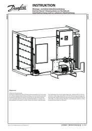
<strong>FCD</strong> <strong>302</strong> – the One Box Concept<br />
reduces your Total Cost of Ownership<br />
Total Cost of Ownership, TCO, is a<br />
primary focus in the decision making<br />
process when buying complex technical<br />
equipment. A lower fi rst cost is no<br />
longer the smart way to buy. The price<br />
has to be sensible, but alongside the<br />
price there are a whole host of factors<br />
that infl uence the overall cost of the<br />
equipment during its lifetime. Those<br />
factors, from the costs of ordering,<br />
through to the running and maintenance<br />
costs, can combine to total more<br />
than the original purchase price,<br />
turning a cheap buy into a very costly<br />
ownership.<br />
The all new VLT® Decentral Drive<br />
<strong>FCD</strong> <strong>302</strong> completes the transition of<br />
MAINTENANCE<br />
MAINTENANCE<br />
MAINTENANCE<br />
UPFRONT COST<br />
TCO<br />
OPERATION<br />
VLT® to a true One Box Concept with<br />
the lowest Total Cost of Ownership<br />
(TCO).<br />
It’s really that simple – everything<br />
needed to control the motor is contained<br />
within the IP 66/NEMA 4X drive<br />
enclosure. Just loop the mains cable<br />
into the box, and out to the next box,<br />
connect a cable to the motor and<br />
you’re ready to run. Add a high speed<br />
fi eldbus cable and your drives are an<br />
integral part of the whole drives<br />
control network. No need for an<br />
external 24 V DC power supply, no<br />
need for an external controller or<br />
motor switch – it’s all in the <strong>FCD</strong> <strong>302</strong>.<br />
INSTALLATION<br />
Every aspect of the <strong>FCD</strong> <strong>302</strong> contributes<br />
to the lowest TCO.<br />
Its unique design is intended to<br />
simplify ordering, installation, commissioning,<br />
operation and maintenance.<br />
Performance and operation<br />
In performance and operation terms,<br />
the <strong>FCD</strong> <strong>302</strong> shares a common platform<br />
with the <strong>Danfoss</strong> VLT® Automation-<br />
Drive range, meaning there’s no new<br />
learning involved and less time spent<br />
discussing the application with<br />
<strong>Danfoss</strong>’ drives specialists.<br />
Documentation and parts<br />
There’s less documentation and fewer<br />
parts and no need for fi eld distribution<br />
or drop-down boxes and it’s a global<br />
product design with local approvals<br />
and documentation available in a wide<br />
selection of languages.<br />
Simple interface<br />
There’s a clear interface between the<br />
installation box and the control<br />
section. That means just one drawing<br />
detailing the electric assembly/<br />
installation box.
Orderhandling<br />
Ordering is simplifi ed by the limited<br />
number of ordering lines required. This<br />
means there is less maintenance of<br />
purchasing orders and reduced risk of<br />
ordering the wrong parts – or missing<br />
parts altogether.<br />
At incoming goods there are fewer<br />
parts to check-in so less time taken to<br />
compare delivery to original order, less<br />
risk of missing parts, fewer inventory<br />
locations and less space required for<br />
storage.<br />
Installation<br />
With fewer numbers of boxes to be<br />
mounted, in fewer locations, that’s a<br />
saving in time and man-hours. Fewer<br />
cables cut time and cost and less<br />
money spent on cable management<br />
systems. No external 24 V DC supply is<br />
required so that’s another cable less<br />
and the cost of a central dc power<br />
supply out of the equation. Fewer<br />
connections and terminations also<br />
reduces labor cost at installation and<br />
lowers the likelihood of failure due to<br />
poor or wrong connectivity.<br />
Commissioning<br />
The One Box Concept means that<br />
commissioning time is signifi cantly<br />
reduced. A multi-lingual graphical<br />
display with on-board manual means<br />
no lost time searching for the manual.<br />
The HMI (human machine interface),<br />
based upon the award winning VLT®<br />
display, has a customized display to<br />
display just the parameters you decide<br />
are important to you.<br />
The <strong>FCD</strong> <strong>302</strong> also makes use of the VLT®<br />
Software Tool MCT 10, proven in use in<br />
the fi eld with thousands of VLT® drives.<br />
Programs can be stored and shared,<br />
drive to drive; OEMs can pre-commission<br />
drives prior to despatch, making<br />
for faster commissioning of the<br />
completed installation on-site. Flexible<br />
PC connection through USB, RS485 and<br />
HPFP and a capability facilitate programme<br />
is available as download via<br />
internet to update the OEM’s factory<br />
settings at the end-user’s plant, which<br />
simplifi es and reduces cost of commissioning.<br />
Service<br />
The <strong>FCD</strong> <strong>302</strong> is probably the simplest<br />
and easiest drive to service which<br />
<strong>Danfoss</strong> has ever developed. Self-diagnostic<br />
troubleshooting combined with<br />
an on-board manual accessed through<br />
the graphical display makes faultfi nding<br />
and troubleshooting easy. All<br />
alarms and operations are logged in<br />
the memory for easy access and<br />
interpretation of past events.<br />
The twin part design dramatically<br />
reduces the time necessary to locate<br />
any failure area and replace the failed<br />
part, minimizing downtime. The failed<br />
part can be replaced by untrained<br />
personnel and spares inventory is<br />
dramatically reduced. No longer<br />
shelves loaded with vulnerable printed<br />
circuit boards (and never the right one<br />
available). Just two parts – a top and a<br />
bottom to make service fast and<br />
reliable.<br />
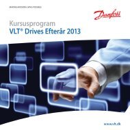
Six LEDs indicate the current device status<br />
– for further programming and confi guration<br />
a graphical control panel identical to the<br />
displays of the FC-series can be connected from<br />
the outside.<br />
The twin part design of the <strong>FCD</strong> <strong>302</strong> allows for<br />
easy and fast servicing<br />
9
10<br />
<strong>FCD</strong> <strong>302</strong> – the One Box Concept<br />
All you need is in one box<br />
Integrated 24 V supply<br />
24 V DC control supply is provided by<br />
the drive supplying remote I/Os<br />
distribution.<br />
Power looping<br />
The new <strong>FCD</strong> <strong>302</strong> facilitates internal<br />
power looping. Terminals for 6 mm 2<br />
(big box) or 4 mm 2 (small box) power<br />
cable inside the enclosure allows<br />
connection of multiple units in the<br />
same branch.<br />
Ethernet switch<br />
Integrated Ethernet switch/ hub with<br />
the two RJ-45 ports are available in the<br />
drive for easy daisy-chaining of<br />
Ethernet communication.<br />
Fieldbusses are routed easily, without<br />
adding commissioning time, by<br />
connecting Ethernet or Profi bus based<br />
fi eld buses to a M12 pluggable interface.<br />
PROFIBUS communication<br />
Straight and easy access to the springloaded<br />
terminals for daisy-chaining.<br />
Decentral I/O<br />
Connection of all input/output devices<br />
is via IP 67 rated M12 connectors on the<br />
<strong>FCD</strong> <strong>302</strong>.<br />
Control terminals<br />
Specially developed spring-loaded<br />
cage clamps enhance reliability and<br />
facilitate easy commissioning and<br />
service.<br />
EMC and Network eff ects<br />
The VLT® Decentral Drive complies as<br />
standard with EMC limits A1 according<br />
to the EN 55011 norm.<br />
The standard integrated DC coils also<br />
ensure low harmonic load on the<br />
network according to EN 61000-3-12<br />
and increase the lifespan of the drive.<br />
Display connection<br />
The same award-winning Local Control<br />
Panel as for FC-drives, can also be used<br />
with the <strong>FCD</strong><strong>302</strong>. Connection can be<br />
made from the outside, without the<br />
need for opening the box, through the<br />
built-in LCP plug.<br />
The info button makes the printed<br />
manual virtually redundant. The<br />
Automatic Motor Adaptation, Quick<br />
Set-Up menu and large graphic display<br />
make commissioning and operation a<br />
breeze.<br />
Built-in Smart Logic Controller<br />
The Smart Logic Controller is a simple<br />
but clever way to keep your drive,<br />
motor and application working<br />
together. The controller monitors a<br />
specifi ed event. When an event occurs,<br />
the controller triggers a specifi ed act<br />
and starts monitoring the next event<br />
continuing for up to 20 steps before<br />
returning to step one.<br />
Safety<br />
The VLT® Decentral Drive <strong>FCD</strong> <strong>302</strong><br />
comes standard with safe stop functionality.<br />
The solution is approved by<br />
authorities for category 3 installations<br />
in accordance with<br />
EN 954-1 and SIL2/IEC 61508.<br />
This feature prevents the drive from<br />
starting unintentionally. Enhanced<br />
safety features are available as options.<br />
PC-software<br />
The drive can also be commissioned via<br />
the built-in USB/RS485 connection or a<br />
fi eldbus from the VLT® set-up software<br />
MCT 10. Access to the USB-port is made<br />
from the outside, without the need for<br />
opening the box, just by removing the<br />
cap on the dedicated hole.<br />
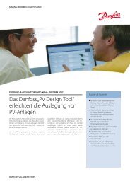
Built-in DC coils to limit harmonic distortion Easy accessable terminals for internal looping<br />
Easy access for PC software connection
Two dimensions<br />
The VLT® Decentral Drive <strong>FCD</strong> <strong>302</strong><br />
is available in two frame size<br />
dimensions.<br />
11
12<br />
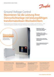
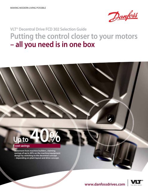
Connection examples<br />
3 phase<br />
power<br />
input<br />
Mechanical<br />
brake<br />
+10Vdc<br />
-10Vdc-<br />
+10Vdc<br />
0/4-20 mA<br />
-10Vdc-<br />
+10Vdc<br />
0/4-20 mA<br />
91 (L1)<br />
92 (L2)<br />
93 (L3)<br />
95 (PE)<br />
122(MBR+)<br />
123(MBR-)<br />
50 (+10 V OUT)<br />
53 (A IN)<br />
54 (A IN)<br />
55 (COM A IN)<br />
12 (+24 V OUT)<br />
13 (+24 V OUT)<br />
18 (D IN)<br />
19 (D IN)<br />
20 (COM D IN)<br />
27 (D IN/OUT)<br />
29 (D IN/OUT)<br />
32 (D IN)<br />
33 (D IN)<br />
37 (D IN)<br />
S201<br />
1 2<br />
S202<br />
1 2<br />
The diagram shows the port terminals<br />
of the <strong>FCD</strong> <strong>302</strong>. Additional options will<br />
expand the number of terminals.<br />
The numbers indicated refer to the<br />
terminal numbers of the drives.<br />
ON<br />
ON<br />
ON/I=0-20mA<br />
OFF/U=0-10V<br />
24V<br />
OV<br />
P 5-00<br />
Switch Mode<br />
Power Supply<br />
10Vdc<br />
15mA<br />
24V (NPN)<br />
OV (PNP)<br />
24V (NPN)<br />
OV (PNP)<br />
24V (NPN)<br />
OV (PNP)<br />
24V (NPN)<br />
OV (PNP)<br />
24V (NPN)<br />
OV (PNP)<br />
24V (NPN)<br />
OV (PNP)<br />
24Vdc<br />
130/600mA<br />
S801<br />
1 2<br />
5V<br />
ON<br />
RS-485<br />
Interface<br />
(U) 96<br />
(U) 97<br />
(W) 98<br />
(PE) 99<br />
(R+) 82<br />
(R-) 81<br />
relay1<br />
03<br />
02<br />
01<br />
relay2<br />
06<br />
05<br />
04<br />
(COM A OUT) 39<br />
0V (A OT) 42<br />
ON=Terminated<br />
OFF=Open<br />
S801<br />
Users can set the mode of the analog<br />
inputs 53 and 54 by using the S201 and<br />
S202 switches.<br />
The <strong>FCD</strong> <strong>302</strong> has a RS485 and an USB<br />
interface as standard. The RS485<br />
GX<br />
(N RS-485) 69<br />
(P RS-485) 68<br />
(COM RS-485) 61<br />
Brake<br />
resistor<br />
240Vac, 2A<br />
240Vac, 2A<br />
400Vac, 2A<br />
Analog Output<br />
0/4-20 mA<br />
(PNP) = Source<br />
(NPN) = Sink<br />
RS-485<br />
Motor<br />
130BB703.10<br />
terminations are integrated in the drive<br />
(S801). The drive can be equipped with<br />
a fi eldbus option if necessary.<br />
To switch from NPN to PNP logic for the<br />
digital signals, use parameter 5-00.
Power and currents<br />
Mains Supply 3 x 380 – 480 VAC<br />
Frequency Converter PK37 PK55 PK75 P1K1 P1K5 P2K2 P3K0<br />
Typical Shaft Output [kW] 0.37 0.55 0.75 1.1 1.5 2.2 3.0<br />
Typical Shaft Output [HP] at 460 V<br />
Output current<br />
0.5 0.75 1.0 1.5 2.0 3.0 4.0<br />
Continuous (3 x 380-440 V) [A] 1.3 1.8 2.4 3.0 4.1 5.2 7.2<br />
Intermittent (3 x 380-440 V) [A] 2.1 2.9 3.8 4.8 6.6 8.3 11.5<br />
Continuous (3 x 441-480 V) [A] 1.2 1.6 2.1 3.0 3.4 4.8 6.3<br />
Intermittent (3 x 441-480 V) [A]<br />
Continuous kVA (400 V AC) [kVA]<br />
1.9<br />
0.9<br />
2.6<br />
1.3<br />
3.4<br />
1.7<br />
4.8<br />
2.1<br />
5.4<br />
2.8<br />
7.7<br />
3.9<br />
10.1<br />
5.0<br />
Continuous kVA (460 V AC) [kVA] 0.9 1.3 1.7 2.4 2.7 3.8 5.0<br />
Max. cable size: (mains, motor, brake) [mm2 ➜<br />
/ AWG] 4/11 6/10<br />
Max. input current<br />
Continuous (3 x 380-440 V) [A] 1.2 1.6 2.2 2.7 3.7 5.0 6.5<br />
Intermittent (3 x 380-440 V) [A] 1.9 2.6 3.5 4.3 5.9 8.0 10.4<br />
Continuous (3 x 441-480 V) [A] 1.0 1.4 1.9 2.7 3.1 4.3 5.7<br />
Intermittent (3 x 441-480 V) [A] 1.6 2.2 3.0 4.3 5.0 6.9 9.1<br />
Recommended fuse size gG-10 gG-16<br />
Recommended max. pre-fuses IEC/UL [A] gG-25<br />
Recommended circuit breaker (small box) CTI-45MB<br />
Recommended circuit breaker (big box) CTI-25M 047b3151<br />
Power loss at max. load [W] 35 42 46 58 62 88 116<br />
Effi ciency 0.93 0.95 0.96 0.96 0.97 0.97 0.97<br />
Weight [kg] (small box) 9.8 X<br />
Weight [kg] (big box) 13.9<br />
➜<br />
Dimensions<br />
Small frame size (0.37 – 2.2 kW/0.5 – 3.0 HP) Large frame size (0.37 – 3 kW/0.5 – 4.0 HP)<br />
All measurements are in mm<br />
13
14<br />
Ordering type code for <strong>FCD</strong> <strong>302</strong><br />
Position 1 2 3 4 5 6 7 8 9 10 11 12 13 14 15 16 17 18 19 20 21 22 23 24 25 26 27 28 29 30 31 32 33 34 35 36 37 38 39<br />
Fixed F C D 3 0 2 P T 4 H 1 X A B X X X X X D<br />
Variants K 3 7 B 6 6 X 1 X X X X X X X X X X X<br />
K 5 5 W 6 6 S 3 E M E C E E 0 R 0<br />
K 7 5 W 6 9 X F F F P N U<br />
1 K 1 Y H L Z<br />
1 K 5 R K<br />
2 K 2 T<br />
3 K 0<br />
[01-03] Product group<br />
<strong>FCD</strong> VLT® Decentral Drive <strong>FCD</strong> <strong>302</strong><br />
[04-06] Frequency converter series<br />
<strong>302</strong> VLT® Decentral Drive<br />
[07-10] Power size<br />
PK37 0.37 kW / 0.5 HP<br />
PK55 0.55 kW / 0.75 HP<br />
PK75 0.75 kW / 1.0 HP<br />
P1K1 1.1 kW / 1.5 HP<br />
P1K5 1.5 kW / 2.0 HP<br />
P2K2 2.2 kW / 3.0 HP<br />
P3K0 3.0 kW / 4.0 HP<br />
PXXX<br />
Installation box only<br />
(without power section)<br />
[11-12] Phases, mains voltage<br />
T Three phase<br />
4 380 – 480 V<br />
X X X<br />
[13-15] Enclosure<br />
B66 Standard Black – IP 66/NEMA 4X<br />
W66 Standard White – IP 66 /NEMA 4X<br />
W69 Hygienic White – IP 69K/NEMA 4X<br />
[16-17] RFI fi lter<br />
H1 RFI fi lter class A1/C2<br />
[18] Brake<br />
X No brake<br />
S Brake + mechanical brake supply<br />
[19] Hardware confi guration<br />
1<br />
Complete product, small enclosure,<br />
stand alone mount<br />
3<br />
X<br />
Y<br />
R<br />
T<br />
Complete product, large enclosure,<br />
stand alone mount<br />
Drive part, small enclosure<br />
(No installation box)<br />
Drive part, large enclosure<br />
(No installation box)<br />
Installation box, small enclosure,<br />
stand alone mount (No drive part)<br />
Installation box, large enclosure,<br />
stand alone mount (No drive part)<br />
[20] Brackets<br />
X No brackets<br />
E Flat brackets<br />
F 40 mm brackets<br />
[21] Threads type<br />
X No installation box<br />
M Metric threads<br />
[22] Switch option<br />
X No switch option<br />
E Service switch on mains input<br />
F Service switch on motor output<br />
H<br />
Circuit breaker & mains disconnect<br />
(large enclosure only)<br />
NOTE: For availabillity of specifi c options and confi gurations please refer to (Confi gurator)<br />
K<br />
Service switch on mains input<br />
with additional looping terminals<br />
(large enclosure only)<br />
[23] Display<br />
X No display connector<br />
C With display connector<br />
[24] Sensor plugs<br />
X No sensor plugs<br />
E Direct mount 4xM12<br />
F Direct mount 6xM12<br />
[25] Motor plug<br />
X No motor plug<br />
[26] Mains plug<br />
X No mains plug<br />
[27] Fieldbus plug<br />
X No fi eldbus plug<br />
E M12 Ethernet<br />
P M12 Profi bus<br />
[28] Reserved<br />
X<br />
[29-30] A option<br />
AX No A option<br />
A0 PROFIBUS DP<br />
AN EtherNet/IP<br />
AL PROFINET<br />
[31-32] B option<br />
BX No B option<br />
BR Encoder option<br />
BU Resolver option<br />
BZ Safety PLC Interface<br />
[33-37] Reserved<br />
XXXXX<br />
[38-39] D option<br />
DX No D option<br />
D0 24 VDC back-up input
Options and Specifi cations<br />
Fieldbus options<br />
■ PROFIBUS DP<br />
■ PROFINET<br />
■ EtherNet/IP<br />
Hardware options<br />
■ Mounting brackets<br />
■ Service switch<br />
■ Internal circuit breaker<br />
■ M12 sensor plugs<br />
■ 24 V DC input for control supply<br />
■ Brake chopper<br />
■ Electromechanical brake control<br />
and supply<br />
■ Fieldbus plugs<br />
Application options<br />
■ VLT® Encoder Input MCB 102<br />
■ VLT® Resolver Input MCB 103<br />
■ VLT® Funcitional Safety Option<br />
MCB 108<br />
Mains supply (L1, L2, L3)<br />
Supply voltage 380 – 480 V ±10%<br />
Supply frequency 50/60 Hz<br />
True Power Factor (λ) 0.92 nominal at rated load<br />
Displacement Power Factor (cos ф) (>0.98)<br />
Switching on input supply<br />
Output data (U, V, W)<br />
2 times/min.<br />
Output voltage 0 – 100% of supply<br />
Output frequency<br />
0 – 1000 Hz<br />
0 – 300 Hz (Flux mode)<br />
Switching on output Unlimited<br />
Ramp times<br />
Digital inputs<br />
0.01 – 3600 sec.<br />
Programmable digital inputs 4 (6)<br />
Logic PNP or NPN<br />
Voltage level 0 – 24 V DC<br />
Note: One/two digital inputs can be programmed as digital outputs<br />
Analogue inputs<br />
Number of analogue inputs 2<br />
Modes Voltage or current<br />
Voltage level -10 to +10 V (scaleable)<br />
Current level<br />
Pulse/encoder inputs<br />
0/4 – 20 mA (scaleable)<br />
Programmable pulse/encoder inputs 2<br />
Voltage level<br />
Digital output<br />
0 – 24 V DC (PNP positive logic)<br />
Programmable digital/pulse outputs 2<br />
Voltage level at digital/frequency output<br />
Analogue output<br />
0 – 24 V<br />
Programmable analogue outputs 1<br />
Current range<br />
Relay outputs<br />
0/4 – 20 mA<br />
Programmable relay outputs<br />
Integrated 24 V supply<br />
2<br />
Max. load 600 mA<br />
Accessories Description Ordering no.<br />
Mounting brackets extended 40 mm brackets 130B5771<br />
Mounting brackets Flat brackets 130B5772<br />
LCP cable Preconfectioned cable to be used between inverter and LCP 130B5776<br />
Brake resistor 1750 ohm 10 W/100% For mounting inside installation box below motor terminals 130B5778<br />
Brake resistor 350 ohm 10 W/100% For mounting inside installation box below motor terminals 130B5780<br />
VLT® Control Panel LCP 102 Graphical display for programming and read out 130B1078<br />
Venting membrane, goretex Preventing condensation inside enclosure 175N2116<br />
PE termination, M16/20 Stainless steel 175N2703<br />
Spare parts Description Ordering no.<br />
Protection cover Plastic protection cover for inverter part (small box/ large box) 130B5770/130B5789<br />
Gasket Gasket between installation box and inverter part (small box/ large box) 130B5773/130B5790<br />
Accessory bag Spare cable clamps and screews for shield termination 130B5774<br />
Service switch Spare switch for mains or motor disconnect 130B5775<br />
LCP plug Spare plug for mounting in installation box 130B5777<br />
Main termination board For mounting in installation box 130B5779<br />
M12 sensor plugs Set of two M12 sensor plugs for mounting in cable gland hole 130B5411<br />
Control card Control card with 24 V backup 130b5783<br />
Control card PROFIBUS Control card Profi bus with 24 V backup 130b5781<br />
Control card EtherNet Control card Ethernet with 24 V backup 130b5788<br />
Control card PROFINET Control card Profi net with 24 V backup 130b5794<br />
15
What VLT® is all about<br />
<strong>Danfoss</strong> VLT Drives is the world leader among dedicated drives providers<br />
– and still gaining market share.<br />
Environmentally<br />
responsible<br />
VLT® products are manufactured with<br />
respect for the safety and well-being of<br />
people and the environment.<br />
All activities are planned and performed<br />
taking into account the individual employee,<br />
the work environment and the<br />
external environment. Production takes<br />
place with a minimum of noise, smoke<br />
or other pollution and environmentally<br />
safe disposal of the products is preprepared.<br />
UN Global Compact<br />
<strong>Danfoss</strong> has signed the UN Global<br />
Compact on social and environmental<br />
responsibility and our companies act<br />
responsibly towards local societies.<br />
EU Directives<br />
All factories are certifi ed according to<br />
ISO 14001 standard. All products fulfi l<br />
the EU Directives for General Product<br />
Safety and the Machinery directive.<br />
<strong>Danfoss</strong> VLT Drives is, in all product<br />
series, implementing the EU Directive<br />
concerning Hazardous Substances in<br />
Electrical and Electrical Equipment<br />
(RoHS) and is designing all new product<br />
series according to the EU Directive on<br />
Waste Electrical and Electronic Equipment<br />
(WEEE).<br />
Impact on energy savings<br />
One year’s energy savings from our annual<br />
production of VLT® drives will save<br />
the energy equivalent to the energy<br />
production from a major power plant.<br />
Better process control at the same time<br />
improves product quality and reduces<br />
waste and wear on equipment.<br />
Dedicated to drives<br />
Dedication has been a key word since<br />
1968, when <strong>Danfoss</strong> introduced the<br />
world’s fi rst mass produced variable<br />
speed drive for AC motors – and<br />
named it VLT®.<br />
Twenty fi ve hundred employees<br />
develop, manufacture, sell and service<br />
drives and soft starters in more than<br />
one hundred countries, focused only<br />
on drives and soft starters.<br />
Intelligent and innovative<br />
Developers at <strong>Danfoss</strong> VLT Drives have<br />
fully adopted modular principles in<br />
development as well as design, production<br />
and confi guration.<br />
Tomorrow’s features are developed in<br />
parallel using dedicated technology<br />
platforms. This allows the development<br />
of all elements to take place in parallel,<br />
at the same time reducing time to<br />
market and ensuring that customers<br />
always enjoy the benefi ts of the latest<br />
features.<br />
Rely on the experts<br />
We take responsibility for every<br />
element of our products. The fact that<br />
we develop and produce our own<br />
features, hardware, software, power<br />
modules, printed circuit boards, and<br />
accessories is your guarantee of reliable<br />
products.<br />
Local backup – globally<br />
VLT® motor controllers are operating in<br />
applications all over the world and<br />
<strong>Danfoss</strong> VLT Drives’ experts located in<br />
more than 100 countries are ready to<br />
support our customers with application<br />
advice and service wherever they<br />
may be.<br />
<strong>Danfoss</strong> VLT Drives experts don’t stop<br />
until the customer’s drive challenges<br />
are solved.<br />
<strong>Danfoss</strong> VLT Drives, 4401 N. Bell School Rd., Loves Park, IL 61111, Tel. +1 (815) 639-8600 (main),<br />
Tel. +1 (800) 432-6367 (24 Hour Service for Drives), Fax +1 (815) 639-8000, www.danfossdrives.com, Email: salesinformation@danfoss.com<br />
DKDD.PB.750.A1.22 VLT® is a trademark of <strong>Danfoss</strong> A/S Produced by PE-MMSC 2012.10 – 177R0365