R & D Marine Flexible Shaft Couplings - PYI Inc.
R & D Marine Flexible Shaft Couplings - PYI Inc.
R & D Marine Flexible Shaft Couplings - PYI Inc.

Create successful ePaper yourself
Turn your PDF publications into a flip-book with our unique Google optimized e-Paper software.
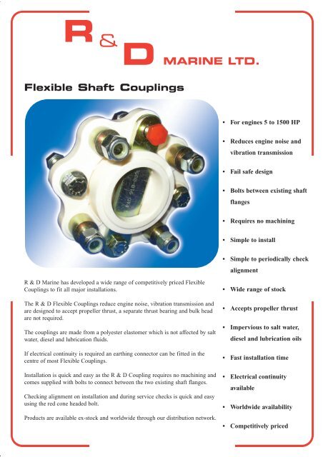
<strong>Flexible</strong> <strong>Shaft</strong> <strong>Couplings</strong><br />
R & D <strong>Marine</strong> has developed a wide range of competitively priced <strong>Flexible</strong><br />
<strong>Couplings</strong> to fit all major installations.<br />
The R & D <strong>Flexible</strong> <strong>Couplings</strong> reduce engine noise, vibration transmission and<br />
are designed to accept propeller thrust, a separate thrust bearing and bulk head<br />
are not required.<br />
The couplings are made from a polyester elastomer which is not affected by salt<br />
water, diesel and lubrication fluids.<br />
If electrical continuity is required an earthing connector can be fitted in the<br />
centre of most <strong>Flexible</strong> <strong>Couplings</strong>.<br />
Installation is quick and easy as the R & D Coupling requires no machining and<br />
comes supplied with bolts to connect between the two existing shaft flanges.<br />
Checking alignment on installation and during service checks is quick and easy<br />
using the red cone headed bolt.<br />
Products are available ex-stock and worldwide through our distribution network.<br />
• For engines 5 to 1500 HP<br />
• Reduces engine noise and<br />
vibration transmission<br />
• Fail safe design<br />
• Bolts between existing shaft<br />
flanges<br />
• Requires no machining<br />
• Simple to install<br />
• Simple to periodically check<br />
alignment<br />
• Wide range of stock<br />
• Accepts propeller thrust<br />
• Impervious to salt water,<br />
diesel and lubrication oils<br />
• Fast installation time<br />
• Electrical continuity<br />
available<br />
• Worldwide availability<br />
• Competitively priced
R & D <strong>Marine</strong> <strong>Flexible</strong> <strong>Shaft</strong> <strong>Couplings</strong><br />
How to Select (details required)<br />
1. Engine horse power and Engine Speed<br />
2. Gearbox type and reduction ratio<br />
3. Gearbox flange details. Diameter of flange. Diameter of register. Pitch circle diameter of fixing holes. Size and quantity of holes<br />
(Pitch circle diameter is the distance between the centre of hole at 12 O`clock position to the centre of the hole at 6 o`clock)<br />
Example<br />
1. Ford 150 HP at 2500 RPM<br />
2. Borg Warner Velvet Drive 72C 2:1 Reduction<br />
3. 5” Flange, 2.500 dia Register, 4.250 PCD, 4 off holes 0.437 diameter<br />
To calculate Power of coupling required. Horse Power of Engine x Reduction Ratio x 100 = HP/100rpm<br />
Engine Speed<br />
150 x 2 x 100 = 12 HP/100 rpm Coupling Required 910-009 Borg Warner<br />
2500<br />
The R & D 910 Series couplings consist of a contoured flexible disc moulded in tough yet resilient new type Polyester Elastomer. The contoured disc<br />
gives clearance for bolt heads, and is able to flex freely to take up any temporary misalignment of the engine and shaft, due to flexing of the boat<br />
structure or the engine moving on its rubber vibration isolation mountings. Forward thrust is taken in compression on the disc between the two half<br />
couplings and reverse thrust is taken again in compression on the disc between the two fail safe straps. In the unlikely event of a disc failure, the steel<br />
straps make the coupling fail safe and ensure drive is maintained in both forward and reverse.<br />
<strong>Couplings</strong> as standard are non-conducting but we can supply a silver impregnated rubber element to fit in the centre of the coupling between<br />
the two fail safe straps to give continuity if required.<br />
<strong>Flexible</strong> Coupling Information<br />
<strong>Flexible</strong><br />
Coupling<br />
910-001<br />
910-002<br />
910-003<br />
910-004<br />
910-005<br />
910-006<br />
910-007<br />
910-009<br />
910-012<br />
910-013<br />
910-014<br />
910-015<br />
910-016<br />
910-017<br />
910-018<br />
910-019<br />
910-020<br />
910-021<br />
910-022<br />
910-024<br />
910-025<br />
910-026<br />
910-027<br />
910-028<br />
910-029<br />
910-030<br />
910-032<br />
910-033<br />
910-034<br />
910-035<br />
910-036<br />
910-037<br />
910-038<br />
910-039<br />
910-040<br />
910-041<br />
910-042<br />
910-043<br />
910-044<br />
910-045<br />
910-046<br />
910-047<br />
910-048<br />
910-049<br />
910-050<br />
910-051<br />
910-052<br />
910-053<br />
910-054<br />
910-055<br />
910-057<br />
910-058<br />
910-059<br />
910-060<br />
Manufacturer<br />
B/W, PRM, ZF-Hurth, Technodrive<br />
Yanmar<br />
B/W, PRM, ZF-Hurth, Twin Disc<br />
B/W,PRM, ZF-Hurth<br />
Paragon<br />
Twin Disc, ZF-Hurth<br />
Volvo<br />
B/W, PRM, ZF-Hurth, Volvo<br />
Yanmar<br />
Bukh<br />
B/W, PRM, ZF-Hurth, Technodrive<br />
Self Change 350HD<br />
Self Change 700HD<br />
Twin Disc<br />
PRM<br />
Volvo<br />
Volvo<br />
Enfield, Sonic<br />
Twin Disc<br />
Twin Disc<br />
B/W, PRM, ZF-Hurth, Twin Disc<br />
Twin Disc<br />
ZF W320 320A<br />
Bukh<br />
B/W, ZF-Hurth, Volvo<br />
B/W, PRM, ZF-Hurth, Twin Disc<br />
Twin Disc, ZF-Hurth<br />
Open Centre V Drive<br />
Twin Disc<br />
Yanmar<br />
Taipeoungyang TK 250<br />
Twin Disc<br />
PRM<br />
Dong-I DMT 170HL<br />
Yanmar<br />
B/W, PRM, ZF-Hurth, Volvo<br />
Allison M25<br />
Dong-I DMT 260H<br />
Twin Disc MG 5111 SC<br />
ZF 325-1A Volvo Flange<br />
Twin Disc 510A/5114A<br />
Twin Disc MG 521<br />
Lister<br />
Dong-I DMT 150H<br />
Open Centre V Drive<br />
Open Centre V Drive<br />
B/W, Hurth, Volvo<br />
Dong-I DMT 70T, 90T, 100T<br />
Volvo<br />
TMP<br />
Gearbox Flange Dimensions <strong>Flexible</strong> Coupling Details<br />
Diameter<br />
mm <strong>Inc</strong>h<br />
101.6 4.00<br />
101.6 4.00<br />
146.0 5.75<br />
101.6 4.00<br />
101.6 4.00<br />
146.0 5.75<br />
101.6 4.00<br />
127.0 5.00<br />
127.0 5.00<br />
90.0 3.54<br />
101.6 4.00<br />
222.2 8.75<br />
260.4 10.25<br />
184.2 7.25<br />
184.2 7.25<br />
101.6 4.00<br />
101.6 4.00<br />
101.6 4.00<br />
228.6 9.00<br />
266.7 10.5<br />
146.0 5.75<br />
146.0 5.75<br />
225 8.86<br />
90.0 3.54<br />
127.0 5.00<br />
292.1 11.5<br />
146.0 5.75<br />
146.0 5.75<br />
127.0 5.00<br />
340.0 13.38<br />
127.0 5.00<br />
130.0 5.12<br />
178.0 7.00<br />
184.2 7.25<br />
184.2 7.25<br />
292.1 11.5<br />
287.2 11.3<br />
101.6 4.00<br />
127.0 5.00<br />
340.0 13.38<br />
228.6 9.00<br />
292.1 11.5<br />
228.6 9.00<br />
205.0 8.07<br />
230.0 9.00<br />
279.4 11.00<br />
120.7 4.75<br />
218 8.58<br />
146.0 5.75<br />
102.0 4.01<br />
127.0 5.00<br />
178.0 7.00<br />
101.6 4.00<br />
112.8 4.44<br />
No<br />
Bolts<br />
4<br />
4<br />
6<br />
4<br />
4<br />
6<br />
4<br />
4<br />
4<br />
4<br />
4<br />
6<br />
6<br />
6<br />
6<br />
4<br />
4<br />
2<br />
8<br />
8<br />
6<br />
6<br />
8<br />
4<br />
4<br />
8<br />
6<br />
6<br />
4<br />
8<br />
4<br />
4<br />
6<br />
6<br />
6<br />
8<br />
6<br />
4<br />
4<br />
8<br />
8<br />
6<br />
6 (8)<br />
10<br />
8<br />
8<br />
6<br />
6<br />
6<br />
4<br />
4<br />
6<br />
4<br />
2<br />
Nom Dia<br />
Of Holes<br />
mm <strong>Inc</strong>h<br />
10.0 0.39<br />
10.0 0.39<br />
12.7 0.50<br />
10.0 0.39<br />
9.7 0.38<br />
16.0 0.63<br />
10.0 0.39<br />
11.2 0.44<br />
10.0 0.39<br />
8.1 0.32<br />
10.0 0.39<br />
11.2 0.44<br />
16.0 0.63<br />
19.0 0.75<br />
16.0 0.63<br />
10.0 0.39<br />
10.0 0.39<br />
11.2 0.44<br />
22.6 0.89<br />
25.4 1.00<br />
12.7 0.5<br />
16.0 0.63<br />
17.0 0.67<br />
8.1 0.32<br />
11.2 0.44<br />
25.4 1.00<br />
12.7 0.5<br />
16.0 0.63<br />
11.2 0.44<br />
25.4 1.00<br />
10.0 0.39<br />
12.3 0.48<br />
14.3 0.56<br />
19.0 0.75<br />
16.0 0.63<br />
25.4 1.00<br />
25.1 0.98<br />
10.0 0.39<br />
11.2 0.44<br />
25.4 1.00<br />
19.0 0.75<br />
21.0 0.826<br />
22.6 0.89<br />
18.0 0.71<br />
22.6 0.89<br />
19.0 0.75<br />
11.2 0.44<br />
20.0 0.79<br />
12.7 0.50<br />
11.2 0.44<br />
11.2 0.44<br />
16.0 0.63<br />
10.0 0.39<br />
11.2 0.44<br />
Bolt Pitch<br />
Circle<br />
mm <strong>Inc</strong>h<br />
82.55 3.25<br />
78.00 3.07<br />
120.6 4.75<br />
82.55 3.25<br />
82.55 3.25<br />
120.6 4.75<br />
80.0 3.15<br />
107.9 4.25<br />
100.0 3.93<br />
74.5 2.93<br />
82.55 3.25<br />
190.5 7.50<br />
228.6 9.00<br />
152.4 6.00<br />
152.4 6.00<br />
80.0 3.15<br />
80.0 3.15<br />
76.0 3.00<br />
190.5 7.50<br />
222.2 8.75<br />
120.6 4.75<br />
120.6 4.75<br />
196 7.72<br />
74.5 2.93<br />
107.9 4.25<br />
247.6 9.75<br />
120.6 4.75<br />
120.6 4.75<br />
107.9 4.25<br />
295.3 11.63<br />
104.8 4.13<br />
107.9 4.25<br />
152.0 5.99<br />
152.4 6.00<br />
152.4 6.00<br />
247.6 9.75<br />
240.0 9.45<br />
78.0 3.07<br />
107.9 4.25<br />
295.3 11.63<br />
190.5 7.50<br />
240.0 9.45<br />
190.5 7.50<br />
170.0 6.69<br />
190.5 7.50<br />
241.3 9.50<br />
98.5 3.88<br />
180.0 7.09<br />
120.6 4.75<br />
107.9 4.25<br />
107.9 4.25<br />
152.0 5.98<br />
80.0 3.15<br />
81.0 3.19<br />
Diameter<br />
mm <strong>Inc</strong>h<br />
114.3 4.5<br />
114.3 4.5<br />
152.4 6.0<br />
114.3 4.5<br />
114.3 4.5<br />
152.4 6.0<br />
114.3 4.5<br />
143.0 5.63<br />
135.0 5.31<br />
114.3 4.5<br />
114.3 4.5<br />
222.2 8.75<br />
276.4 10.88<br />
190.5 7.5<br />
190.5 7.5<br />
114.3 4.5<br />
114.3 4.5<br />
108.0 4.25<br />
222.2 8.75<br />
276.4 10.88<br />
152.4 6.0<br />
152.4 6.0<br />
228.6 9.0<br />
114.3 4.5<br />
143.0 5.63<br />
292.1 11.5<br />
152.4 6.0<br />
152.4 6.0<br />
143.0 5.63<br />
348.0 13.7<br />
143.0 5.63<br />
143.0 5.63<br />
190.5 7.50<br />
190.5 7.50<br />
190.5 7.50<br />
292.1 11.5<br />
292.1 11.5<br />
114.3 4.5<br />
143.0 5.6<br />
348.0 13.7<br />
222.2 8.75<br />
292.1 11.5<br />
222.2 8.75<br />
223.0 8.78<br />
230.0 9.00<br />
260.4 11.25<br />
150.9 5.94<br />
222.2 8.75<br />
152.4 6.0<br />
143.0 5.63<br />
143.0 5.63<br />
190.5 7.50<br />
114.3 4.5<br />
112.8 4.44<br />
Capacity<br />
/100 rpm<br />
kW HP<br />
3.73 5<br />
2.24 3<br />
14.92 20<br />
5.97 8<br />
5.22 7<br />
14.92 20<br />
2.24 3<br />
9.69 13<br />
7.46 10<br />
2.24 3<br />
2.24 3<br />
32.1 43<br />
48.47 65<br />
29.84 40<br />
29.84 40<br />
2.24 3<br />
3.73 5<br />
1.87 2.5<br />
48.47 65<br />
63.38 85<br />
20.88 28<br />
20.88 28<br />
48.47 65<br />
3.73 5<br />
14.92 20<br />
89.48 120<br />
27.6 37<br />
27.6 37<br />
8.95 12<br />
119.3 160<br />
7.46 10<br />
9.69 13<br />
41.0 55<br />
41.0 55<br />
41.0 55<br />
104.4 140<br />
67.0 90<br />
3.73 5<br />
5.97 8<br />
171.5 230<br />
48.47 65<br />
67.0 90<br />
48.47 65<br />
56 75<br />
63.38 85<br />
89.48 120<br />
7.46 10<br />
35.8 48<br />
17.9 24<br />
5.2 7<br />
18.64 25<br />
41.0 55<br />
5.96 8<br />
2.42 3.25<br />
O These couplings are fitted with a shouldered bush to locate in the gearbox flange O These flexible couplings have been approved by BUREAU VERITAS<br />
X These flexible couplings have been approved by LLOYDS REGISTER OF SHIPPING # For the Hurth HBW 150 V Gearbox an adaptor 202-351 is required (22.3 mm 0.875" long)<br />
For the IRM 220A Gearbox, we can supply adapter plate 202-384 (54mm 2.125" long) and for the Twin Disc 502 Gearbox, adapter plate 202-148 (54mm 2.125" long) that bolt onto<br />
flexible coupling 910-003, 910-025 or 910-032 and with half coupling 202-037 or 202-054, alternatively clamp type 202-176 or 202-178<br />
HP x 0.7457 = KW KW x 1.341 = HP<br />
Register<br />
mm <strong>Inc</strong>h<br />
63.5 2.50<br />
50.0 1.97<br />
76.2 3.00<br />
63.5 2.50<br />
66.7 2.63<br />
76.2 3.00<br />
60.0 2.36<br />
63.5 2.50<br />
65.0 2.56<br />
47.0 1.85<br />
63.5 2.50<br />
152.4 6.00<br />
152.4 6.00<br />
95.25 3.75<br />
95.25 3.75<br />
60.0 2.36<br />
60.0 2.36<br />
---- ----<br />
152.4 6.00<br />
127.0 5.00<br />
76.2 3.00<br />
76.2 3.00<br />
140 5.51<br />
47.0 1.85<br />
63.5 2.50<br />
152.4 6.00<br />
76.2 3.00<br />
76.2 3.00<br />
63.5 2.50<br />
152.4 6.00<br />
63.5 2.50<br />
63.5 2.50<br />
100 3.937<br />
95.25 3.75<br />
95.25 3.75<br />
152.4 6.00<br />
160.0 6.30<br />
50.0 1.97<br />
63.5 2.50<br />
152.4 6.00<br />
152.4 6.00<br />
150.0 5.905<br />
152.4 6.00<br />
140.0 5.51<br />
152.4 6.00<br />
152.4 6.00<br />
63.5 2.50<br />
140.0 5.51<br />
76.2 3.00<br />
63.5 2.50<br />
63.5 2.50<br />
100.0 3.94<br />
60.0 2.36<br />
---- ----<br />
Length<br />
mm <strong>Inc</strong>h<br />
32.5 1.28<br />
32.5 1.28<br />
47.5 1.87<br />
35.6 1.40<br />
34.5 1.35<br />
47.5 1.87<br />
43.7 1.72<br />
45.0 1.77<br />
45.0 1.77<br />
32.5 1.28<br />
32.5 1.28<br />
43.2 1.70<br />
58.0 2.28<br />
60.7 2.39<br />
60.7 2.39<br />
32.5 1.28<br />
32.5 1.28<br />
41.7 1.64<br />
44.5 1.75<br />
56.7 2.23<br />
49.8 1.96<br />
49.8 1.96<br />
44.5 1.75<br />
32.5 1.28<br />
52.4 2.06<br />
58.4 2.30<br />
55.4 2.18<br />
55.4 2.18<br />
45.0 1.77<br />
108.0 4.25<br />
45.0 1.77<br />
51.1 2.01<br />
63.3 2.49<br />
63.3 2.49<br />
63.3 2.49<br />
58.4 2.30<br />
58.4 2.30<br />
32.5 1.28<br />
45.0 1.77<br />
108.0 4.25<br />
44.5 1.75<br />
58.4 2.30<br />
62.7 2.47<br />
124.0 4.88<br />
101.6 4.0<br />
58.4 2.30<br />
69.9 2.75<br />
45.0 1.77<br />
47.5 1.87<br />
45.0 1.77<br />
52.4 2.06<br />
63.3 2.49<br />
35.6 1.40<br />
38.1 1.50<br />
Bolt<br />
Dia<br />
M10<br />
M10<br />
1/2 UNF<br />
M10<br />
3/8 UNF<br />
1/2 UNF<br />
M10<br />
7/16 UNF<br />
M10<br />
M8<br />
M10<br />
7/16 UNF<br />
5/8 UNF<br />
5/8 UNF<br />
5/8 UNF<br />
M10<br />
M10<br />
7/16 UNF<br />
1/2 UNF<br />
5/8 UNF<br />
1/2 UNF<br />
1/2 UNF<br />
1/2 UNF<br />
M8<br />
7/16 UNF<br />
5/8 UNF<br />
1/2 UNF<br />
1/2 UNF<br />
7/16 UNF<br />
5/8 UNF<br />
M10<br />
7/16 UNF<br />
M14<br />
5/8 UNF<br />
5/8 UNF<br />
5/8 UNF<br />
5/8 UNF<br />
M10<br />
7/16 UNF<br />
3/4 UNF<br />
1/2 UNF<br />
5/8 UNF<br />
1/2 UNF<br />
M18<br />
1/2 UNF<br />
5/8 UNF<br />
7/16 UNF<br />
1/2 UNF<br />
1/2 UNF<br />
7/16 UNF<br />
7/16 UNF<br />
5/8 UNF<br />
M10<br />
7/16 UNF<br />
Ref<br />
XO<br />
O XO<br />
XO<br />
O<br />
XO<br />
O XO<br />
XO<br />
O X O<br />
O X O<br />
XO<br />
O XO<br />
O<br />
O<br />
O XO<br />
O<br />
#<br />
O<br />
O<br />
O<br />
O<br />
O<br />
O<br />
O<br />
O X O<br />
O<br />
O<br />
O<br />
#
Coupling Selection Guide<br />
ALLISON<br />
M25 9" Flange 910-046<br />
BORG WARNER<br />
4" Flange 910-001, 910-004, 910-014<br />
70C<br />
71C<br />
500<br />
1000<br />
1500<br />
5" Flange 910-009(BW) 910-029,<br />
910-044(BW), 910-057<br />
71C<br />
72C<br />
5000<br />
6" Flange 910-003, 910-025, 910-032<br />
73C<br />
7000<br />
BUKH<br />
4" Flange 910-013, 910-028<br />
DONG I<br />
DMT 70T 178 mm Flange 910-058<br />
DMT 90T<br />
DMT 100T<br />
DMT 150H 218 mm Flange 910-053<br />
DMT 170HL 287 mm Flange 910-042<br />
DMT 260H 292 mm Flange 910-047<br />
ENFIELD and SONIC DRIVES<br />
2 Bolt 910-021<br />
LISTER<br />
4 1 ⁄2" Flange 910-052<br />
NEWAGE PRM<br />
S= Shallow Case, D= Deep Case<br />
4" Flange 910-001, 910-004, 910-014<br />
Delta<br />
80<br />
120<br />
150<br />
5" Flange 910-009(PR) 910-044(PR)<br />
101<br />
140<br />
160<br />
260<br />
6" Flange 910-003, 910-025, 910-032<br />
175<br />
265<br />
301<br />
302<br />
310<br />
401<br />
402<br />
500<br />
750<br />
601 3:1<br />
1000 3:1<br />
7 1 ⁄4" Flange 910-018, 910-040<br />
601 4:1<br />
1000 4:1<br />
1200S<br />
1500S<br />
1750S<br />
10 1 ⁄2" Flange 910-024<br />
1200D<br />
1500D<br />
1750D<br />
PARAGON<br />
4" Flange 910-005<br />
SELF CHANGE GEARS<br />
8 3 ⁄4" Flange 910-015<br />
350HD<br />
10 3 ⁄4" Flange 910-016<br />
700<br />
TAIPEOUNGYANG<br />
178 mm Flange 910-038<br />
TK250<br />
TECHNODRIVE<br />
4” Flange 910-001, 910-004, 910-014<br />
TMC30<br />
TMC40<br />
TMC50<br />
TMC60<br />
TM260<br />
5" Flange 910-009(PR) 910-029<br />
TM93 910-044(PR)<br />
TM93A<br />
TM170<br />
TM170A<br />
TM345<br />
TM345A<br />
TM485A<br />
TM545A<br />
TM880A<br />
6" Flange 910-006, 910-026, 910-033<br />
TM130B<br />
TM200B up to 1.28: 1<br />
TM265<br />
TM265A<br />
7 1 ⁄4" Flange 910-018<br />
TMC200B up to 4.48: 1<br />
TM1200A<br />
TMP<br />
2 Bolt 910-060<br />
5" Flange 910-009(PR) 910-044(PR)<br />
12000<br />
TWIN DISC<br />
SC= Shallow Case, DC= Deep Case<br />
4" Flange 910-001, 910-004, 910-014<br />
MG 340<br />
MG 360<br />
MG5010SC<br />
MG5011SC<br />
MG5010V<br />
4 3 ⁄4" Flange Adaptor 202-148 with<br />
MG502-I 910-003, 910-025, 910-032<br />
MG502-V<br />
5" Flange 4 1 ⁄8 PCD 910-036<br />
MG5010A<br />
MG5011A<br />
5" Flange 4 1 ⁄4 PCD 910-009(PR) 910-044(PR)<br />
MG5005A<br />
MG5012SC<br />
MG5015A<br />
MG5020SC<br />
MG5055A<br />
6" Flange 910-006, 910-026,910-033<br />
MG5010DC<br />
MG5050<br />
MG5050-V<br />
MG5050-A<br />
MG5061SC<br />
MG5061-A<br />
MG5061V<br />
MG5062V<br />
MG506-1<br />
MG506A-1<br />
MG507-1<br />
MG507A-1<br />
MG5075IV<br />
MG5075-A<br />
MG5075SC<br />
7 1 ⁄4" Flange 910-017, 910-039<br />
MG506DC<br />
MG5065A<br />
MG507-1<br />
MG507-1SC<br />
MG507-2SC<br />
MG507A-2<br />
MG5075A needs adaptor 202-356<br />
MG5075SC<br />
MG5075IV<br />
MG5081SC<br />
MG5081A needs adaptor 202-356<br />
MG5082A<br />
MG5082SC<br />
MG5085SC needs adaptor 202-356<br />
MG5085A needs adaptor 202-356<br />
MG5090A<br />
MG509SC<br />
MG509U<br />
MG5091SC<br />
MG5095A<br />
MGX5095A<br />
TWIN DISC cont`d<br />
9" Scalloped Flange 910-048<br />
MG5111SC<br />
MG5114SC<br />
9" Flange 910-022, 910-050<br />
MG510SC<br />
MG510A<br />
MG5111A<br />
MG5114A<br />
MG5111V,<br />
MG5114V<br />
MG514CU<br />
MG514U<br />
MG5135A<br />
10 1 ⁄2" Flange 910-024<br />
MG5091DC<br />
MG509DC<br />
MG510DC<br />
MG5111DC<br />
MG5114DC<br />
MG5113<br />
MG514DC<br />
VOLVO<br />
4" Flange 910-007<br />
MS<br />
RB<br />
4" Flange 910-019, 910-020, 910-059<br />
MS 2<br />
MS 10<br />
MS 15<br />
MS25<br />
5" Flange 910-009(VO), 910-029<br />
MS 3 910-044(VO), 910-057<br />
MS4<br />
MS5<br />
HS25A<br />
HS45A<br />
HS63A<br />
YANMAR (KANZAKI)<br />
4" Flange 78mm PCD 910-002<br />
KBW10 910-043<br />
KM2<br />
KM3<br />
KM35<br />
5" Flange 100mm PCD 910-012<br />
KBW20<br />
KBW21<br />
KM4<br />
KM4A<br />
KMH4A<br />
5 1 ⁄2"Flange 4 1 ⁄4 PCD 910-009, 910-029, 910-037<br />
KM40<br />
KM5<br />
KMH50<br />
6" Flange 910-006, 910-026, 910-033<br />
KMH6<br />
KMH60<br />
ZF-HURTH<br />
4" Flange 910-001, 910-004, 910-014<br />
HBW HSW ZF<br />
35<br />
40 4M<br />
50 5M<br />
100 10M<br />
125H 12<br />
125 12M<br />
150 15M<br />
150A 15MA<br />
250 25M<br />
250H 25<br />
250A 25A<br />
25MA<br />
30M<br />
45A 1.25:1<br />
450D 45C<br />
4 3 ⁄4 " Adaptor 202-384 with 910-003<br />
910-025, 910-032<br />
IRM ZF<br />
220A-1 220A<br />
225A<br />
<strong>Couplings</strong> 910-030, 910-035, 910-041 and 910-045 will require suitable adaptors for the gearbox flange<br />
ZF HURTH cont`d<br />
5" Flange 910-009(PR)<br />
910-029, 910-044(PR)<br />
HBW HSW ZF<br />
360<br />
450H2<br />
450A2 45A<br />
450D 45C<br />
630H1 63<br />
630A1 63A<br />
630D 63C<br />
88C<br />
90TS<br />
90ATS<br />
110TS<br />
6" Flange 13.2 mm bolt holes 910-003,<br />
910-025, 910-032<br />
ZF<br />
45<br />
6" Flange 16.3mm bolt holes 910-006,<br />
910-026, 910-033<br />
HSW IRM ZF<br />
45-1<br />
800A2 80A<br />
800A3 80-1A<br />
85A<br />
220PL 220 needs adaptor<br />
202-329<br />
280A<br />
280-1<br />
280V-LD 280-1A<br />
280PL 280IV<br />
280<br />
285A<br />
285IV<br />
286<br />
286A<br />
286IV<br />
300TS<br />
300-1TS<br />
300ATS<br />
300-1ATS<br />
301PL-2 301C<br />
301A-2 301A<br />
300VTS 300IVTS<br />
110ATS<br />
110IVTS<br />
8" Flange 910-049<br />
IRM ZF<br />
311PL 311<br />
325-1A Volvo<br />
350PL-2 350<br />
350A-2 350A<br />
350PL-1<br />
350A-1<br />
350TS<br />
350ATS<br />
350V 350V<br />
350V-LD 350IV<br />
8 3 ⁄4" Flange 910-027<br />
IRM ZF<br />
320-2 W320<br />
320A<br />
ZF-HURTH V DRIVE<br />
4" Flange Adaptor 202-351 with<br />
HSW ZF 910-034, 910-055<br />
150V 15MIV<br />
5" Flange 910-034, 910-055<br />
HSW ZF<br />
90IVTS<br />
630V 63IV<br />
6" Flange 910- 054<br />
HSW ZF<br />
110IVTS<br />
220V-2 220IV<br />
800V1 80IV<br />
800V2 80-1IV<br />
8" Flange 910-049<br />
ZF<br />
325IV
INSTALLATION PROCEDURE FOR R & D MARINE COUPLINGS<br />
1. Roughly align engine and stern gear without flexible coupling i.e. only two rigid half couplings pushed together.<br />
2. Bolt “R & D <strong>Marine</strong>” coupling between the two rigid couplings. Tightening details as below.<br />
3. Check alignment of engine by placing feeler gauges between the RED CONE<br />
HEADED BOLT and the rigid half coupling. Repeat for the SAME bolt at 90° intervals by<br />
rotating the shaft.<br />
4. If the gap is the same in all four positions, the engine is accurately aligned. Recommended<br />
minimum to maximum gap difference: 0.25 mm / 0.010 inch.<br />
5. Run installation to bring engine compartment to working temperature.<br />
Re-check torque settings.<br />
EARTHING CONNECTORS<br />
‘R & D <strong>Marine</strong>’ Earthing Connector consists of a silver impregnated rubber strip, which when fitted through the axis of the coupling<br />
between the two fail safe straps gives electrical continuity. R & D have sizes to fit most 910 series couplings.<br />
INSTALLATION PROCEDURE FOR R&D EARTHING CONNECTORS<br />
1. While carrying out the following procedure, ensure that the connector is not contaminated by grease or dirt.<br />
2. Before fitting the coupling into the drive train, remove 2 off bolts holding one of the fail safe straps.<br />
3. Remove the fail safe strap to uncover the hole in the centre of the coupling.<br />
4. Roll up the earthing connector (lengthways)<br />
as tight as possible.<br />
R & D <strong>Marine</strong> Earthing Connector Application Guide<br />
5. Push into the hole previously uncovered by removing the strap<br />
as far as possible.<br />
6. Replace the fail safe strap ensuring that the connector is not<br />
damaged, replace 2 off bolts.<br />
7. Fit the coupling as per the installation instructions.<br />
8. Check electrical continuity on installation and thereafter<br />
at three to six month intervals.<br />
Part No<br />
103-036<br />
103-037<br />
103-038<br />
103-039<br />
103-040<br />
103-041<br />
103-042<br />
103-043<br />
103-044<br />
Meadow Works<br />
Clothall Road<br />
Baldock<br />
Hertfordshire<br />
England<br />
SG7 6PD<br />
Size (mm)<br />
9 x 57<br />
11 x 57<br />
15 x 57<br />
17 x 57<br />
19 x 57<br />
23 x 57<br />
25 x 57<br />
15 x 75<br />
17 x 75<br />
Gearbox<br />
Flange<br />
Check Gap<br />
<strong>Shaft</strong><br />
Flange<br />
Recommended tightening torque:<br />
M8 - 27 Nm 20 lbsft 3/8 UNF - 40 Nm 30 lbsft M10 - 61 Nm 45 lbsft 7/16 UNF - 81 Nm 60 lbsft M12 - 108 Nm 80 lbsft<br />
1/2 UNF - 100 Nm 75 lbsft 5/8 UNF - 210 Nm 155 lbsft M18 - 338 Nm 250 lbsft 3/4 UNF - 366 Nm 270 lbsft<br />
To Suit Coupling<br />
910-021<br />
910-001, 002, 007, 013, 014, 019, 020, 028, 043<br />
910-004, 005<br />
910-003, 006, 009, 012, 036, 037, 044, 052<br />
910-017, 018, 025, 026<br />
910-029, 039, 040<br />
910-032, 033<br />
910-015, 016, 022, 024, 046, 048, 053<br />
910-030, 041, 042, 047, 051<br />
Contact Us By:<br />
Tel: +44 (0)1462 892391<br />
Fax: +44 (0)1462 896448<br />
Web Site: www.randdmarine.com<br />
E mail: info@randdmarine.com<br />
06/09
<strong>Flexible</strong> Engine Mountings<br />
R & D <strong>Marine</strong> has developed a comprehensive range of fail safe competitively<br />
priced Engine Mountings to fit all major installations.<br />
Shear mountings are available where good isolation is required and<br />
compression mounts where there is a restriction on the available space.<br />
Installation is made as quick and easy as possible with slotted holes and height<br />
adjusting studs to simplify alignment.<br />
Products are available ex-stock and worldwide through our distribution network.<br />
• Capacity 30 - 2000 lbs<br />
per mount<br />
• Good vibration isolation<br />
• Fail safe design<br />
• Will withstand roll<br />
over test<br />
• Competitively priced<br />
• Wide range of stock<br />
• Available in standard sizes<br />
• Accepts propeller thrust<br />
• Pre-loaded<br />
• Slotted holes to assist<br />
alignment<br />
• Height adjusting to simplify<br />
alignment<br />
• Fast installation time<br />
• Worldwide availability
R & D <strong>Marine</strong> Engine Mountings<br />
How to select (details required)<br />
1. Engine type, number of cylinders<br />
2. Type of gearbox and reduction ratio<br />
3. Weight of engine and gearbox combined by weighing or manufacturers literature<br />
4. Is flywheel in conventional place between the engine and gearbox<br />
5. Position of engine mounting points<br />
6. Find centre of gravity by balancing on a roller (if possible)<br />
Weight on each front mount = W x b<br />
2 x (a+b)<br />
Example: Totalweightofengineandgearbox=1200lbs<br />
Distance a (balance point to front mount) = 17 inches<br />
W<br />
Distance b (balance point to rear mount) = 14 inches<br />
Weight on each Rear Mount =<br />
W x a<br />
2 x (a+b)<br />
Weight of Engine & Gearbox<br />
Front mount 1200 x 14<br />
2 x (17 + 14)<br />
Rear Mount 1200 x 17<br />
2 x (17 + 14)<br />
= 270 lbs per front mount<br />
=329lbsperrearmount<br />
a b<br />
7. If Centre of Gravity cannot be found, assume weight distribution of 60% on rear mounts, with 40% on front<br />
mounts. (if rear mount is in line with flywheel).<br />
Type of Engine Recommended Mounting Type<br />
Double Acting Small Compression Compression Small Shear Medium & Large Shear<br />
2 & 3 Cylinder Long Stroke 800-032, 034, 042 800-036 800-003, 4, 5<br />
1, 2 & 3 Cylinder 800-033, 036 800-038, 039 800-010, 011<br />
Short Stroke High Speed 800-040, 041<br />
4 Cylinder 800-033, 036 800-003, 4, 5 SUPER MOUNTS<br />
See page 3<br />
6 Cylinder and More 800-003, 4, 5 SUPER MOUNTS<br />
See Page 3<br />
800-015, 016, 017<br />
Installation Details<br />
Maximum clearance between the underside of the height adjusting nut and top washer must not be more than 10mm. If more<br />
height is required use a spacer under the mounting casting. This applies to all mountings in the R & D <strong>Marine</strong> Range.<br />
5/8 UNF<br />
5/8 UNF<br />
PLASTIC OIL<br />
SHIELD<br />
42.7<br />
1.68<br />
Compression Mountings<br />
117.6<br />
4.63<br />
42.0<br />
1.65<br />
Front Mount Point Rear Mount Point<br />
Balance<br />
Point<br />
143.5<br />
5.65<br />
12.7 0.5<br />
12.7 0.5<br />
101.6 4.00<br />
130.3 5.13<br />
101.6 4.00<br />
130.3 5.13<br />
76.2<br />
3.0<br />
71.4<br />
2.81<br />
Units of measurement: Black Millimetres Red <strong>Inc</strong>hes<br />
R & D MARINE COMPRESSION MOUNTING<br />
This is a low height mounting with minimum deflection<br />
5/8 Stud<br />
Part No Capacity per mount<br />
kg lbs<br />
800-003 45-82 100-180<br />
800-004 73-168 160-370<br />
800-005 145-227 320-500<br />
Mount Pre-loaded 1.5mm 0.06 inch<br />
Deflection 2.3mm 0.09 inch<br />
Height adjusting nut thickness 14mm 0.55 inch<br />
R & D MARINE COMPRESSION MOUNTING<br />
This mounting is a competitive, low height<br />
medium capacity mount giving good engine control<br />
5/8 Stud<br />
Part No Capacity per mount<br />
kg lbs<br />
800-033 86 190<br />
800-036 136 300<br />
Deflection 1.65mm 0.065 inch<br />
Height adjusting nut thickness 14mm 0.55 inch
Rectangular Shear Mountings<br />
The R & D Rectangular Shear Mountings offer low height with the best combination of stiffness.<br />
Soft vertically and at right angles to the crankshaft to isolate vibration, stiff fore and aft to take the propeller thrust.<br />
12mm or 5/8 UNF<br />
X<br />
5/8 or 3/4 UNF<br />
X<br />
5/8 or 3/4 UNF<br />
X<br />
X<br />
3/4 UNF<br />
5/8 or 3/4 UNF<br />
Max Height<br />
40.7<br />
1.60<br />
Max Height<br />
63.5<br />
2.50<br />
101.6 4.00<br />
127.0 5.00<br />
‘X’ Dimensions on initial installation should not be less 3.8mm 0.15 inch<br />
63.5<br />
2.50<br />
‘X’ Dimensions on initial installation should not be less 3.8mm 0.15 inch<br />
63.5<br />
2.50<br />
‘X’ Dimensions on initial installation should not be less 3.8mm 0.15 inch<br />
60.4<br />
2.38<br />
138.0<br />
5.43<br />
Max Height<br />
Max Height<br />
12.7 0.5<br />
12.7 0.5<br />
12.7 0.5<br />
12.7 0.5<br />
12.7 0.5<br />
101.6 4.00<br />
127.0 5.00<br />
101.6 4.00<br />
127.0 5.00<br />
127.0 5.00<br />
165 6.50<br />
101.6 4.00<br />
165 5.00<br />
‘X’ Dimensions on initial installation should not be less 3.8mm 0.15 inch<br />
50.8<br />
2.0<br />
62.0<br />
2.44<br />
62.0<br />
2.44<br />
Units of measurement: Black Millimetres Red <strong>Inc</strong>hes<br />
R & D MARINE SMALL SHEAR LOADED MOUNTING<br />
This mounting has a low height giving good vibration isolation<br />
12mm Stud 5/8 Stud<br />
Part No Capacity per mount Part No Capacity per mount<br />
kg lbs kg lbs<br />
800-038 14-41 30-90 800-040 14-42 30-91<br />
800-039 32-77 70-170 800-041 32-78 70-171<br />
Mount Pre-loaded 1.8mm 0.07 inch<br />
Deflection 1.8-3.4mm 0.07-0.14 inch<br />
Height adjusting<br />
nut thickness : 10mm 0.39 inch 14mm 0.55 inch<br />
Maximum height: 99mm 3.9 inch 116mm 4.57 inch<br />
R & D MARINE SHEAR LOADED “SUPER MOUNTS”<br />
Fitted with an oil shield to protect the rubber<br />
5/8 Stud 3/4 Stud<br />
Part No Capacity per mount Part No Capacity per mount<br />
kg lbs kg lbs<br />
800-037 23-80 50-175<br />
800-010 36-105 80-230 800-020 36-106 80-231<br />
800-011 55-186 120-410 800-021 55-187 120-411<br />
800-012 114-255 250-560 800-022 114-256 250-561<br />
800-014 136-309 300-680 800-023 136-310 300-681<br />
Mount Pre-loaded 2.3mm 0.09 inch<br />
Deflection 2.3-5.4mm 0.09-0.21 inch<br />
Height adjusting<br />
nut thickness : 14mm 0.55 inch 11mm 0.43 inch<br />
Maximum height: 137mm 5.38 inch 165mm 6.5 inch<br />
R & D MARINE SHEAR LOADED “SUPER MOUNTS”<br />
Fitted with an oil shield to protect the rubber<br />
3/4 Stud<br />
Part No Capacity per mount<br />
kg lbs<br />
800-051 36-108 80-235<br />
800-052 55-187 120-415<br />
800-053 114-257 250-565<br />
800-054 136-311 300-685<br />
Mount Pre-loaded 2.3mm 0.09 inch<br />
Deflection 2.3-5.4mm 0.09-0.21 inch<br />
Height adjusting double nut and washer thickness<br />
25mm 0.97 inch<br />
R & D MARINE SHEAR LOADED “SUPER MOUNTS”<br />
Fitted with an oil shield to protect the rubber<br />
5/8 Stud 3/4 Stud<br />
Part No Capacity per mount Part No Capacity per mount<br />
kg lbs kg lbs<br />
800-062 23-81 50-176<br />
800-024 36-106 80-232<br />
62.0<br />
2.44 800-025 55-187 120-412<br />
800-026 114-256 250-562<br />
800-028 36-107 80-233<br />
800-029 55-188 120-413<br />
800-030 114-257 250-563<br />
800-027 136-310 300-682 800-031 136-311 300-683<br />
Mount Pre-loaded 2.3mm 0.09 inch<br />
Deflection 2.3-5.4mm 0.09-0.21 inch<br />
Height adjusting<br />
nut thickness: 14mm 0.55 inch 11mm 0.43 inch<br />
Maximum height: 137mm 5.38 inch 165mm 6.5 inch<br />
83.9<br />
3.3<br />
R & D MARINE SHEAR LOADED “SUPER MOUNTS”<br />
Fitted with an oil shield to protect the rubber<br />
5/8 Stud 3/4 Stud<br />
Part No Capacity per mount Part No Capacity per mount<br />
kg lbs kg lbs<br />
800-013 155-345 340-760 800-035 155-346 340-761<br />
Mount Pre-loaded 2.3mm 0.09 inch<br />
Deflection 2.3-4.8mm 0.09-0.19 inch<br />
Height adjusting<br />
nut thickness: 14mm 0.55 inch 11mm 0.43 inch<br />
Maximum height: 137mm 5.38 inch 152mm 6.0 inch
3/4 UNF<br />
1 UNF<br />
5/8 or 3/4 UNF<br />
R & D <strong>Marine</strong> Engine Mountings<br />
Circular Shear Mountings<br />
85.9<br />
3.38<br />
85.9<br />
3.38<br />
192.0<br />
7.56<br />
162.0<br />
6.38<br />
Double Acting Mounting<br />
Max Height<br />
75.2<br />
2.96<br />
Meadow Works<br />
Clothall Road<br />
Baldock<br />
Hertfordshire<br />
England<br />
SG7 6PD<br />
140 5.50<br />
89 3.5 85.9 3.38<br />
140 5.50<br />
89 3.5 85.9 3.38<br />
101.6 4.00<br />
140 5.5<br />
181.0 7.13<br />
12.7 0.5<br />
12.7 0.5<br />
12.7 0.5<br />
101.6<br />
4.00<br />
101.6<br />
4.00<br />
79.4<br />
3.125<br />
Units of measurement: Black Millimetres Red <strong>Inc</strong>hes<br />
Contact Us By:<br />
Tel: +44 (0)1462 892391<br />
Fax: +44 (0)1462 896448<br />
Web Site: www.randdmarine.com<br />
E mail: info@randdmarine.com<br />
R & D MARINE HEAVY DUTY CIRCULAR<br />
SHEAR MOUNTING<br />
This mounting is designed to give excellent<br />
vibration isolation and is fitted with an oil shield to<br />
protect the rubber<br />
3/4 Stud<br />
Part No Capacity per mount<br />
kg lbs<br />
800-015 228-546 500-1200<br />
800-016 296-682 650-1500<br />
800-017 400-910 880-2000<br />
Mount Pre-loaded 3mm 0.12 inch<br />
Deflection 3-6.4mm 0.012-0.25 inch<br />
Height adjusting nut thickness 16mm 0.63 inch<br />
R & D MARINE HEAVY DUTY CIRCULAR<br />
SHEAR MOUNTING<br />
This mounting is designed to give excellent<br />
vibration isolation and is fitted with an oil shield to<br />
protect the rubber<br />
1.00 Stud<br />
Part No Capacity per mount<br />
kg lbs<br />
800-055 228-546 500-1201<br />
800-056 296-682 650-1501<br />
800-057 400-910 880-2001<br />
Mount Pre-loaded 3mm 0.12 inch<br />
Deflection 3-6.4mm 0.012-0.25 inch<br />
Height adjusting double nut and washer thickness<br />
31.75mm 1.25 inch<br />
R & D MARINE DOUBLE ACTING SHEAR<br />
LOADED MOUNTING<br />
The Double Acting Shear Mount is a unique mounting<br />
incorporating 2 rubber elements which are pre-loaded against<br />
each other, giving excellent isolation together with good<br />
control on problem installations<br />
5/8 Stud 3/4 Stud<br />
Part No Capacity per mount Part No Capacity per mount<br />
kg lbs kg lbs<br />
800-032 46-190 100-420<br />
800-034 73-305 160-670 800-042 73-305 160-671<br />
Mount Pre-loaded 4.8mm 0.19 inch<br />
Deflection 4.8-7.6mm 0.19-0.30 inch<br />
Height adjusting<br />
nut thickness : 14mm 0.55 inch 11mm 0.43 inch<br />
Maximum height 153mm 6.0 inch 153mm 6.0 inch<br />
06/09
������������ ������������ ������� ������� ������� ������� ���� ����<br />
����� ����� ������� ������� ������������<br />
������������<br />
���� ������ ���� ����� ������������ ���� ���� ������� ������ ������� �� ��������� ������<br />
��� ������� ������� ���� ������� ��������������� ���� ����� ���� ��������� ���� �������<br />
����������� ��������� ��� ���� ���� ������� ��������� ������� ������� ����� �� �������<br />
��������� �������� ������ ��� ���������� ���� ������� ���� ����� �������� ��� ���� �������<br />
��������<br />
���� ������� ������� ���� ��� �������� ��� ������������� ������� �������<br />
����������� ���� ����� ��� ���������� ���� ��������� ���������� ������ ������ ������ ��� ������������� ��������<br />
������ ���� ����� ��������� ���������� ���������� ��� ��������� ����� �� ������ ������� ������ ������� ��������<br />
����� ������ ������������� ���������� ������� ���������� �������� ���� ���������� ����� ������ �������<br />
������� ��� ������ ����������� ��������� ��������� ��� ���������� ����� ������ ��� �� ����� �����<br />
��� ���������� ������ ���� ������� ��������� ���� ������� �������� ����� ���������� ��� ��������� �������<br />
������ �������� ����� ���<br />
���������� ��� �����<br />
������� ������ ��������<br />
���� ������ ��������<br />
��������������<br />
�������� ���������������<br />
��������������
���������� ��������������<br />
���� ��� ��<br />
������� ��������������<br />
��� ������ �������������� ����� ������������ ����� ��������<br />
�� �� ��� ������ �������������� ����� ������������ ����� ��������<br />
��� ����� ������������ ����� ��������<br />
��� ����� ������������ ����� ��������<br />
����� ����� ������������ ����� ��������<br />
����� ����� ������������ ����� ��������<br />
����� ������ �������������� ����� ������������ ������ ���������� ����� ��������<br />
����� ���� ������� ����� �������������� �������� ����� ������������ ����� ��������<br />
����� ���� ������� ����� �������������� �������� ����� ������������ ������ ��������� ����� ��������<br />
��� ����� ������������ ���������<br />
��� ����� ��� �������<br />
���� �� ��� ����� ��� �������<br />
������ ����<br />
���� ����� � ������������ ���� ���������� �����<br />
�������� ������ ���� �� ��� ���4���<br />
�������� ������ ���� �� ��� ���4���<br />
�������� ������� ���� �� ��� ���4���<br />
�������� ������� ���� �� ��� ���4���<br />
�������� ������� ���� �� ��� ���4���<br />
��������� ������� ���� �� ��� ��50���<br />
������� �������� ������ ����� ������ ������� ��6���<br />
���� ����<br />
������ �������� ����� ����<br />
���������� ��� �����<br />
��������������<br />
��������������<br />
���� �������� ����
NEW: - High Capacity Super Mount
High Capacity Super Mount<br />
R & D <strong>Marine</strong> introduces the new High Capacity Super Mount to their comprehensive range.<br />
The mounting is designed to suit engine/gearbox installations requiring load capacities per mounting between<br />
500 and 2100 lbs (227 and 954 kg), and is designed to absorb the increased thrust developed by modern light<br />
weight engines.<br />
¾” Stud 1” Stud<br />
Part No. Capacity Per Mount Part No. Capacity Per Mount<br />
kg lbs kg lbs<br />
800-063 227-590 500-1300 800-066 227-591 500-1301<br />
800-064 295-772 650-1700 800-067 295-773 650-1701<br />
800-065 500-954 1100-2100 800-068 500-955 1100-2101<br />
Mount Pre-Loaded: 3mm 0.12”<br />
Deflection: 3-6.4mm 0.012-0.25”<br />
Height Adjusting Double Nut & Washer Thickness (1” UNF Stud): 31.75mm 1.25”<br />
Height Adjusting Nut Thickness (3/4” Stud): 16mm 0.63”<br />
Note: All dimensions listed in millimetres [inches]<br />
Clothall Road,<br />
Baldock,<br />
Hertfordshire.<br />
England. SG7 6PD.<br />
Telephone: Baldock +44 (0)1462 892391<br />
Fax: +44 (0)1462 896448<br />
E mail: info@randdmarine.com<br />
Web Site:<br />
www.randdmarine.com<br />
09/ 09
Damper Drive Plates<br />
R & D <strong>Marine</strong> has developed a wide range of competitively priced Damper<br />
Drive Plates to fit most engine/gearbox combinations.<br />
The R & D Damper Drive Plates reduce gear noise and allow the engine to run<br />
at lower speeds.<br />
Linear Stiffness elements for general applications and High-Deflection elements<br />
to stop gear noise and spline wear at slow speeds.<br />
All dampers are designed to be Fail-Safe and maintain the drive if the flexible<br />
element fails.<br />
The flexible elements are made from a Polyester Elastomer which has good heat<br />
qualities and is not affected by salt water, diesel and lubrication oils.<br />
Non-standard items are available for special installations, maximum back plate<br />
diameter of 533mm (21.0").<br />
Installation is made quick and easy as the R & D Damper Drive Plate requires<br />
no machining and is ready to bolt to the flywheel.<br />
Products are available ex-stock and worldwide through our distribution network.<br />
• For engines up to 800 HP<br />
• Torque range 60-1400 lb ft<br />
• Reduces gear noise<br />
• Allows engine to run at<br />
lower speeds<br />
• Fail safe design<br />
• Machined ready to install<br />
• Elements suitable for every<br />
application<br />
• Element has good heat<br />
qualities<br />
• Special back plates up to<br />
533mm (21.0") diameter<br />
• Element is impervious to<br />
salt water, diesel and<br />
lubrication oils<br />
• Wide range of stock<br />
• Competitively priced<br />
• No springs to rust or fret<br />
• Worldwide availability
R & D <strong>Marine</strong> Damper Drive Plates<br />
Element Selection<br />
Consider the following criteria when making a decision on the element design.<br />
Loop type General purpose robust element which can be mounted either way round on the flywheel and can rotate in either<br />
direction. Linear stiffness up to 3 degrees of deflection.<br />
Hammer Head More torsionally flexible than the loop type, usually has smaller diameter element than our other designs but<br />
still retains the ability to be mounted either way round on the flywheel and rotate in either direction. Three stage stiffness<br />
with up to 9 degrees of deflection.<br />
High Deflection (H/D) Softer than our other designs with a maximum deflection up to 30 degrees, slightly larger diameter<br />
element than other designs and can only be fitted to rotate in the standard direction of rotation (anti-clockwise looking at the<br />
flywheel). With the element facing the gearbox. Suitable for work boats with slow speed applications and pleasure boats.<br />
Details required for Damper Selection<br />
1. Manufacturer of Engine, Engine Horse Power, Engine Speed, Number of cylinders<br />
2. Manufacturer of Gearbox, Model Number and Input Spline Details.<br />
3. Back plate diameter, Number of holes, Size of holes, Pitch circle diameter of holes.<br />
Does the plate fit on the face of the flywheel or locate in a register?<br />
4. Will the element of the Drive Plate fit on the outside of the flywheel or be reversed and fit inside a flywheel recess?<br />
5. Type of application. Pleasure or Work Boat? Does it spend long periods at low engine speeds<br />
• If an existing installation with a failed part •<br />
6. Type and Part Number of Damper that has failed<br />
7. What has failed. Spline or Element/Springs?<br />
Gearbox Spline Details<br />
Gearbox Spline Spline Dia<br />
mm inch<br />
Borg Warner<br />
71, 72, 73, 5000 26T 20/40 DP 35.4 1.394<br />
1000, 1500 22T PA 30 18.5 0.729<br />
500 10T B10 x 23 x 29 29.0 1.142<br />
DIN 5464<br />
7000 SAE 1 1/2 x 10T 38.1 1.50<br />
Newage PRM<br />
Delta 17T 24/48 DP 19.7 0.776<br />
80, 120, 150 10T B10 x 23 x 29 29.0 1.142<br />
DIN 5464<br />
100, 101, 140, 160, 260 SAE 1" x 10T 25.4 1.000<br />
175, 250, 265, 310 SAE 1 1/8" x 10T 28.6 1.125<br />
301. 302, 401, 402, 500, 17T 16/32 DP 28.84 1.135<br />
750<br />
In-Line 301, 302, 401 26T 20/40 DP 35.4 1.394<br />
402, 500, 750<br />
601, 1000 18T 12/24 DP 40.5 1.595<br />
1200, 1500 20T 12/24 DP 44.8 1.761<br />
Paragon<br />
P Series 26T 20/40 DP 35.4 1.394<br />
Parsons<br />
SAE 1 1/2 x 10T 38.1 1.50<br />
Self Change Gear<br />
MRF 350HD 32T 16/32 DP 52.3 2.060<br />
MRF 350 SAE 1 5/8 x 10T 41.3 1.625<br />
Technodrive<br />
TMC 30, 40, 50, 60 10T B10 x 23 x 29 29.0 1.142<br />
DIN 5464<br />
TM 93, 170, 260, 345 26T 20/40 DP 35.4 1.394<br />
485, 545, 880<br />
TMP<br />
1200, 1500 26T 20/40 DP 35.4 1.394<br />
Twin Disc<br />
502, 501 26T 20/40 DP 35.4 1.394<br />
Volvo<br />
140 Leg Old 270-280 Leg SAE 1" x 10T 25.4 1.000<br />
MS3, 4, 5, HS1 Sale Drive 110 26T 20/40 DP 35.4 1.394<br />
New 270-280 Leg<br />
120 Leg, MS 20T 30PA 24/48 DP 22.6 0.89<br />
Yanmar<br />
Kanzaki 20T 30PA 24/48 DP 22.6 0.89<br />
ZF - Hurth<br />
HBW 35, 40, 50, 100, 10T B10 x 23 x 29 29.0 1.142<br />
125, 150 DIN 5464<br />
HSW 125<br />
HBW 250, 360 26T 20/40 DP 35.4 1.394<br />
HSW 450, 630, 800<br />
IRM 220A 26T 20/40 DP 35.4 1.394<br />
WW = Start of<br />
Spline from<br />
Front Face<br />
Torque Design Code Element Rotation<br />
Nm lb ft Fixing<br />
80 60 Loop A 3 x 3/8 (4.00) Either<br />
135 100 Loop B 3 x 3/8 (4.00) Either<br />
135 100 H/D AA 3 x 3/8 (4.00) Anti-Clockwise<br />
135 100 Hammer W 3 x 3/8 (4.00) Either<br />
215 160 Hammer D 5 x 3/8 (5.59) Either<br />
245 180 Loop E 5 x 3/8 (5.59) Either<br />
270 200 Loop F 3 x 1/2 (4.50) Either<br />
270 200 H/D AC 4 x 3/8 (6.00) Anti-Clockwise<br />
270 200 H/D AG 4 x 3/8 (6.00) Anti-Clockwise<br />
340 250 Loop G 5 x 3/8 (5.59) Either<br />
340 250 Hammer Y 5 x 1/2 (5.59) Either<br />
360 270 Loop H 4 x 1/2 (4.50) Either<br />
405 300 Loop J 3 x 1/2 (4.50) Either<br />
405 300 Hammer AJ 3 x 1/2 (4.50) Either<br />
445 330 Loop K 5 x 1/2 (5.59) Either<br />
420 310 Hammer L 5 x 3/8 (5.59) Either<br />
475 350 Hammer U 5 x 1/2 (5.59) Either<br />
540 400 Loop M 5 x 3/8 (5.59) Either<br />
610 450 Loop N 4 x 1/2 (4.50) Either<br />
610 450 Loop V 5 x 1/2 (5.59) Either<br />
670 500 H/D AD 4 x 1/2 (8.00) Anti-Clockwise<br />
745 550 Loop P 5 x 1/2 (5.59) Either<br />
745 550 Hammer R 5 x 1/2 (5.59) Either<br />
940 700 H/D AE 4 x 1/2 (8.00) Anti-Clockwise<br />
1015 750 Loop S 5 x 1/2 (5.59) Either<br />
1630 1200 Loop Z 6 x 5/8 (10.2) Anti-Clockwise<br />
1630 1200 Loop AF 6 x 5/8 (10.2) Clockwise<br />
1901 1400 Loop AH 6 x 5/8 (10.2) Anti-Clockwise
Damper Selection Procedure<br />
Example 1) Ford 150 HP at 2500 RPM 6 Cylinder<br />
2) Borg Warner Velvet Drive 72C Spline 26 teeth 20/40 DP 1.394 diameter<br />
3) Back Plate diameter 14.250, fixing holes 6 x 0.375 diameter on13.500 pcd spaced in 3 groupe of 2. No register<br />
4) Element fits on outside of flywheel<br />
5) Work Boat with a lot of slow speed work.<br />
The R & D Damper comprises 3 main components, Spline plate, Element and Back plate, these 3 components are given a code which make up<br />
the finished part number.. The following procedure will lead you through the selection process.<br />
1. Select the correct power and style of element for the application .<br />
Use the manufacturers maximum torque figure for the engine or calculate from the known data of maximum horsepower rating at<br />
what rpm. Using the example installation above we get 315 lb ft or 427 Nm<br />
To calculate output Torque of engine<br />
Horse Power of Engine x 5250 = Torque lbft 150 x 5250 = 315 lb ft Horse Power of Engine x 7123 = Torque Nm 150 x 7123 = 427 Nm<br />
Engine Speed 2500 Engine Speed 2500<br />
From the Element selection chart we see the most suitable element has a code of AD and a fixing of 4 x 1/2 (8.00)<br />
2. Select the correct Spline Plate to suit the Gearbox Input <strong>Shaft</strong><br />
Using the example, go to the Gearbox Details to find the Borg Warner 72 has a 26 Tooth 20/40 DP input spline. In the Selection Chart<br />
below look down the Element Fixing column find 4 x 1/2 (8.00) looking across find the 26T 20/40 DP input spline, in the next column is<br />
the correct code of 48 for the spline plate. The furthest column to the right gives the list number of the Back Plates available for this<br />
Element fixing, in this case List 7<br />
3. Select the correct Back Plate to suit the Flywheel<br />
Using the example, go to Back Plate List 7 on page 4. Looking down the list find the matching bolt pattern, in this case Back Plate 2<br />
Damper Required for this example Spline Plate 48 Element AD Back Plate 2<br />
Spline<br />
22T PA 30<br />
26T 20/40 DP<br />
17T 24/48 DP<br />
1" x 10 SAE<br />
10T DIN 5464<br />
20T 30PA 24/48 DP<br />
26T 20/40 DP<br />
10T DIN 5464<br />
17T 24/48 DP<br />
17T 16/32 DP<br />
1" x 10 SAE<br />
20T 30PA 24/48 DP<br />
26T 20/40 DP<br />
26T 20/40 DP<br />
1" x 10 SAE<br />
1 1/8" x 10 SAE<br />
17T 16/32 DP<br />
10T DIN 5464<br />
17T 24/48 DP<br />
26T 20/40 DP<br />
26T 20/40 DP Long<br />
18T 12/24 DP<br />
17T 16/32 DP<br />
32T 16/32 DP<br />
1 5/8" x 10<br />
1 1/2" x 10<br />
PR 1500<br />
26T 20/40 DP<br />
26T 20/40 DP Long<br />
18T 12/24 DP<br />
32T 16/32 DP<br />
1 5/8" x 10<br />
1 1/2" x 10<br />
PR 1500<br />
26T 20/40 DP<br />
26T 20/40 DP HT<br />
1 1/2" x 10<br />
1 1/8" x 10 SAE<br />
17T 16/32 DP<br />
1 5/8" x 10<br />
26T 20/40 DP<br />
1" x 10 SAE<br />
17T 16/32 DP<br />
17T 24/48 DP<br />
26T 20/40 DP<br />
17T 16/32 DP<br />
26T 20/40 DP<br />
32T 16/32 DP<br />
PR 1500<br />
26T 20/40 DP<br />
32T 16/32 DP<br />
PR 1500<br />
26T 20/40 DP<br />
26T 20/40 DP<br />
18T 12/24 DP<br />
17T 16/32 DP<br />
Spline<br />
Plate<br />
No<br />
1<br />
2<br />
12<br />
13<br />
22<br />
66<br />
42<br />
43<br />
44<br />
46<br />
45<br />
65<br />
3<br />
5<br />
14<br />
16<br />
18<br />
23<br />
32<br />
4<br />
9<br />
21<br />
31<br />
26<br />
27<br />
11<br />
54<br />
4<br />
9<br />
21<br />
26<br />
27<br />
11<br />
54<br />
6<br />
8<br />
10<br />
17<br />
19<br />
28<br />
7<br />
15<br />
20<br />
41<br />
48<br />
49<br />
57<br />
40<br />
55<br />
56<br />
40<br />
55<br />
56<br />
50<br />
51<br />
52<br />
Group 1<br />
(ZZ1)<br />
A, B, W,<br />
AA<br />
AC<br />
D, L,<br />
Y, U, R,<br />
S<br />
H, N<br />
F, J, AJ<br />
AD<br />
Z, AF<br />
AH<br />
AE<br />
Element Code<br />
AG<br />
Group 2<br />
(ZZ2)<br />
E, G, M<br />
K, V, P<br />
Element<br />
Fixing<br />
3 x 3/8<br />
(4.00)<br />
4 x 3/8<br />
(6.00)<br />
5 x 3/8<br />
(5.593)<br />
5 x 1/2<br />
(5.593)<br />
5 x 1/2<br />
(5.593)<br />
4 x 1/2<br />
(4.50)<br />
3 x 1/2<br />
(4.50)<br />
4 x 1/2<br />
(8.00)<br />
6 x 5/8<br />
(8.00)<br />
6 x 5/8<br />
(8.00)<br />
4 x 1/2<br />
(10.25)<br />
WW<br />
0.0 0.00<br />
2.3 0.09<br />
0.0 0.00<br />
0.0 0.00<br />
0.0 0.00<br />
0.0 0.00<br />
5.0 0.20<br />
0.0 0.00<br />
0.0 0.00<br />
1.8 0.07<br />
2.3 0.09<br />
0.0 0.00<br />
5.0 0.20<br />
5.0 0.20<br />
2.3 0.09<br />
2.3 0.09<br />
1.8 0.07<br />
0.0 0.00<br />
0.0 0.00<br />
5.0 0.20<br />
0.0 0.00<br />
0.0 0.00<br />
1.8 0.07<br />
0.0 0.00<br />
0.0 0.00<br />
0.0 0.00<br />
0.0 0.00<br />
5.0 0.20<br />
0.0 0.00<br />
0.0 0.00<br />
0.0 0.00<br />
0.0 0.00<br />
0.0 0.00<br />
0.0 0.00<br />
5.0 0.20<br />
5.0 0.20<br />
0.0 0.00<br />
2.3 0.09<br />
1.8 0.07<br />
0.0 0.00<br />
8.1 0.32<br />
2.3 0.09<br />
1.8 0.07<br />
1.8 0.07<br />
6.0 0.24<br />
1.8 0.07<br />
0.0 0.00<br />
0.0 0.00<br />
0.0 0.00<br />
0.0 0.00<br />
0.0 0.00<br />
0.0 0.00<br />
0.0 0.00<br />
0.0 0.00<br />
0.0 0.00<br />
0.0 0.00<br />
Black mm<br />
XX<br />
25.4 1.00<br />
25.4 1.00<br />
25.4 1.00<br />
25.4 1.00<br />
25.4 1.00<br />
25.4 1.00<br />
25.4 1.00<br />
25.4 1.00<br />
25.4 1.00<br />
25.4 1.00<br />
25.4 1.00<br />
25.4 1.00<br />
25.4 1.00<br />
25.4 1.00<br />
25.4 1.00<br />
25.4 1.00<br />
25.4 1.00<br />
25.4 1.00<br />
25.4 1.00<br />
28.7 1.13<br />
28.7 1.13<br />
28.7 1.13<br />
28.7 1.13<br />
38.5 1.52<br />
28.7 1.13<br />
28.7 1.13<br />
63.2 2.49<br />
31.8 1.25<br />
31.8 1.25<br />
31.8 1.25<br />
41.7 1.64<br />
31.8 1.25<br />
31.8 1.25<br />
66.3 2.61<br />
29.5 1.16<br />
29.5 1.16<br />
29.5 1.16<br />
29.5 1.16<br />
29.5 1.16<br />
29.5 1.16<br />
29.5 1.16<br />
29.5 1.16<br />
29.5 1.16<br />
29.5 1.16<br />
29.0 1.14<br />
29.0 1.14<br />
29.0 1.14<br />
44.2 1.74<br />
68.6 2.70<br />
44.2 1.74<br />
47.3 1.86<br />
71.9 2.83<br />
47.3 1.86<br />
31.8 1.25<br />
31.8 1.25<br />
31.8 1.25<br />
Damper Dimensions<br />
YY<br />
32.0 1.25<br />
32.0 1.25<br />
32.0 1.25<br />
32.0 1.25<br />
32.0 1.25<br />
32.0 1.25<br />
35.0 1.38<br />
35.0 1.38<br />
35.0 1.38<br />
35.0 1.38<br />
35.0 1.38<br />
35.0 1.38<br />
35.0 1.38<br />
35.0 1.38<br />
35.0 1.38<br />
35.0 1.38<br />
35.0 1.38<br />
35.0 1.38<br />
35.0 1.38<br />
35.0 1.38<br />
43.0 1.69<br />
38.1 1.50<br />
35.0 1.38<br />
57.2 2.25<br />
38.1 1.50<br />
38.1 1.50<br />
79.3 3.12<br />
35.0 1.38<br />
43.0 1.69<br />
38.1 1.50<br />
57.2 2.25<br />
38.1 1.50<br />
38.1 1.50<br />
79.3 3.12<br />
36.0 1.41<br />
36.0 1.41<br />
36.0 1.41<br />
36.0 1.41<br />
36.0 1.41<br />
38.1 1.50<br />
36.0 1.41<br />
36.0 1.41<br />
36.0 1.41<br />
36.0 1.41<br />
36.0 1.41<br />
36.0 1.41<br />
36.0 1.41<br />
57.2 2.25<br />
79.3 3.12<br />
51.6 2.03<br />
57.2 2.25<br />
79.3 3.12<br />
51.6 2.03<br />
39.0 1.53<br />
39.0 1.53<br />
39.0 1.53<br />
Red inches<br />
Group 1<br />
ZZ 1<br />
127 5.00<br />
127 5.00<br />
127 5.00<br />
127 5.00<br />
127 5.00<br />
127 5.00<br />
182 7.13<br />
182 7.13<br />
182 7.13<br />
182 7.13<br />
182 7.13<br />
182 7.13<br />
175 6.90<br />
175 6.90<br />
175 6.90<br />
175 6.90<br />
175 6.90<br />
175 6.90<br />
175 6.90<br />
182 7.13<br />
182 7.13<br />
182 7.13<br />
182 7.13<br />
182 7.13<br />
207 8.13<br />
207 8.13<br />
207 8.13<br />
207 8.13<br />
207 8.13<br />
207 8.13<br />
207 8.13<br />
183 7.19<br />
183 7.19<br />
183 7.19<br />
183 7.19<br />
183 7.19<br />
183 7.19<br />
158 6.19<br />
158 6.19<br />
158 6.19<br />
158 6.19<br />
235 9.25<br />
235 9.25<br />
235 9.25<br />
330 13.00<br />
330 13.00<br />
330 13.00<br />
330 13.00<br />
330 13.00<br />
330 13.00<br />
302 11.88<br />
302 11.88<br />
302 11.88<br />
Group 2<br />
ZZ 2<br />
214 8.43<br />
214 8.43<br />
214 8.43<br />
214 8.43<br />
214 8.43<br />
214 8.43<br />
207 8.13<br />
207 8.13<br />
207 8.13<br />
207 8.13<br />
207 8.13<br />
207 8.13<br />
207 8.13<br />
207 8.13<br />
207 8.13<br />
207 8.13<br />
207 8.13<br />
207 8.13<br />
207 8.13<br />
207 8.13<br />
207 8.13<br />
Back<br />
Plate<br />
List<br />
L1<br />
L2<br />
L3<br />
L3<br />
L4<br />
L5<br />
L6<br />
L7<br />
L8<br />
L8<br />
L9
List 1 Element Fixing 3 x 3/8 (4.00) 3 mm thick plate List 4 Element Fixing 4 x 1/2 (5.593) 6 mm thick plate<br />
4<br />
8<br />
Ref<br />
37<br />
43<br />
49<br />
60<br />
91<br />
Ref<br />
8<br />
37<br />
49<br />
60<br />
91<br />
94<br />
Ref<br />
1<br />
2<br />
3<br />
5<br />
17<br />
25<br />
35<br />
36<br />
40<br />
O/D<br />
Met<br />
155.45<br />
298.5<br />
266.7<br />
263.5<br />
241.3<br />
215.9<br />
314.3<br />
-0.05<br />
-0.13<br />
Remarks<br />
Suit Ford<br />
XLD<br />
And<br />
Mitsubishi<br />
SAE 8<br />
SAE 7 1/2<br />
Beta<br />
SAE 6 1/2<br />
SAE 10<br />
List 7 Element Fixing 4 x 1/2 (8.00) 3 mm thick plate<br />
List 2 Element Fixing 4 x 3/8 (6.00) 3 mm thick plate Ref<br />
O/D<br />
Met<br />
298.5<br />
266.7<br />
241.3<br />
215.9<br />
314.3<br />
-0.05<br />
-0.13<br />
287.4<br />
List 3 Element Fixing 5 x 3/8 (5.593) 3 mm thick plate<br />
O/D<br />
Met<br />
298.5<br />
362<br />
336.5<br />
352.5<br />
314.3<br />
287.4<br />
263.5<br />
266.7<br />
241.3<br />
O/D<br />
Imp<br />
6.12<br />
11.75<br />
10.5<br />
10.375<br />
9.500<br />
8.500<br />
12.375<br />
-0.002<br />
-0.005<br />
SAE 10<br />
O/D<br />
Imp<br />
11.75<br />
10.5<br />
9.500<br />
8.500<br />
12.375<br />
-0.002<br />
-0.005<br />
SAE 10<br />
11.312<br />
O/D<br />
Imp<br />
11.75<br />
14.25<br />
13.24<br />
13.875<br />
12.375<br />
11.312<br />
10.375<br />
10.5<br />
9.500<br />
Flywheel Fixing<br />
Metric<br />
5 x 6.35 on 142<br />
6 x 8.1 on 200<br />
6 x 8.1 on 250<br />
6 x 8.1 on 269.9<br />
6 x 8.1 on 273<br />
12 x 8.1 on 222.3<br />
6 x 8.1 on 244.5<br />
Spaced 3 groups<br />
of 2 apart 23°59`07<br />
12 x 8.1 on 246<br />
12 x 8.1 on 242<br />
6 x 9.5 on 244.5<br />
8 x 8.5 on 222.25<br />
6 x 8.1 on 200<br />
6 x 8.1 on 200<br />
6 x 8.1 on 250<br />
6 x 8.1 on 269.9<br />
6 x 8.1 on 273<br />
8 x 10.6 on 296<br />
Flywheel Fixing<br />
Metric<br />
6 x 8.1 on 200<br />
6 x 8.1 on 250<br />
6 x 8.1 on 269.9<br />
6 x 8.1 on 273<br />
12 x 8.1 on 222.3<br />
6 x 8.1 on 244.5<br />
Spaced 3 groups<br />
of 2 apart 23°59`07<br />
12 x 8.1 on 246<br />
12 x 8.1 on 242<br />
8 x 8.5 on 222.25<br />
6 x 8.1 on 200<br />
6 x 8.1 on 200<br />
6 x 8.1 on 250<br />
6 x 8.1 on 269.9<br />
6 x 8.1 on 273<br />
8 x 10.6 on 296<br />
6 x 9.1 on 269.96<br />
6 x 6.3 on 269.96<br />
Flywheel Fixing<br />
Metric<br />
6 x 8.1 on 200<br />
6 x 8.1 on 250<br />
6 x 8.1 on 269.9<br />
6 x 8.1 on 273<br />
6 x 8.1 on 200<br />
6 x 8.1 on 210<br />
6 x 8.1 on 263<br />
6 x 8.1 on 269.9<br />
6 x 8.1 on 276.3<br />
6 x 8.1 on 289<br />
6 x 8.1 on 295.3<br />
6 x 8.8 on 304.8<br />
6 x 8.1 on 314.4<br />
6 x 9.5 on 320.7<br />
12 x 9.5 on 343<br />
Ford<br />
6 x 8.1 on 200<br />
6 x 8.1 on 210<br />
6 x 8.1 on 263<br />
6 x 8.1 on 269.9<br />
6 x 8.1 on 276.3<br />
6 x 8.1 on 289<br />
6 x 8.1 on 295.3<br />
6 x 8.8 on 304.8<br />
6 x 8.1 on 314.4<br />
6 x 9.5 on 320.7<br />
8 x 10.6 on 333.4<br />
6 x 8.1 on 200<br />
6 x 8.1 on 250<br />
6 x 8.1 on 269.9<br />
6 x 8.1 on 273<br />
8 x 10.6 on 296<br />
6 x 9.1 on 269.96<br />
6 x 6.3 on 269.96<br />
6 x 9.5 on 244.5<br />
12 x 8.1 on 222.3<br />
6 x 8.1 on 244.5<br />
Spaced 3 groups<br />
of 2 apart 23°59`07<br />
12 x 8.1 on 246<br />
12 x 8.1 on 242<br />
8 x 8.5 on 222.25<br />
Flywheel Fixing<br />
Imperial<br />
5 x .25 on 5.593<br />
6 x .32 on 7.875<br />
6 x .32 on 9.843<br />
6 x .32 on 10.625<br />
6 x .32 on 10.75<br />
12 x .32 on 8.750<br />
6 x .32 on 9.625<br />
Spaced 3 groups<br />
of 2 apart 23°59`07<br />
12 x .32 on 9.685<br />
12 x .32 on 9.527<br />
6 x .375 on 9.625<br />
8 x .334 on 8.750<br />
6 x .32 on 7.875<br />
6 x .32 on 7.875<br />
6 x .32 on 9.843<br />
6 x .32 on 10.625<br />
6 x .32 on 10.750<br />
8 x .416 on 11.625<br />
Flywheel Fixing<br />
Imperial<br />
6 x .32 on 7.875<br />
6 x .32 on 9.843<br />
6 x .32 on 10.625<br />
6 x .32 on 10.75<br />
12 x .32 on 8.750<br />
6 x .32 on 9.625<br />
Spaced 3 groups<br />
of 2 apart 23°59`07<br />
12 x .32 on 9.685<br />
12 x .32 on 9.527<br />
8 x .334 on 8.750<br />
6 x .32 on 7.875<br />
6 x .32 on 7.875<br />
6 x .32 on 9.843<br />
6 x .32 on 10.625<br />
6 x .32 on 10.750<br />
8 x .416 on 11.625<br />
6 x .356 on 10.625<br />
3 x .25 on 10.625<br />
Flywheel Fixing<br />
Imperial<br />
6 x .32 on 7.875<br />
6 x .32 on 9.843<br />
6 x .32 on 10.625<br />
6 x .32 on 10.75<br />
6 x .32 on 7.875<br />
6 x .32 on 8.268<br />
6 x .32 on 10.375<br />
6 x .32 on 10.625<br />
6 x .32 on 10.875<br />
6 x .32 on 11.375<br />
6 x .32 on 11.625<br />
6 x .344 on 12.00<br />
6 x .32 on 12.375<br />
6 x .375 on 12.625<br />
12 x .375 on 13.5<br />
Ford<br />
6 x .32 on 7.875<br />
6 x .32 on 8.268<br />
6 x .32 on 10.375<br />
6 x .32 on 10.625<br />
6 x .32 on 10.875<br />
6 x .32 on 11.375<br />
6 x .32 on 11.625<br />
6 x .344 on 12.00<br />
6 x .32 on 12.375<br />
6 x .375 on 12.625<br />
8 x .416 on 13.125<br />
6 x .32 on 7.875<br />
6 x .32 on 9.843<br />
6 x .32 on 10.625<br />
6 x .32 on 10.750<br />
8 x .416 on 11.625<br />
6 x .356 on 10.625<br />
3 x .25 on 10.625<br />
6 x .375 on 9.625<br />
12 x .32 on 8.750<br />
6 x .32 on 9.625<br />
Spaced 3 groups<br />
of 2 apart 23°59`07<br />
12 x .32 on 9.685<br />
12 x .32 on 9.527<br />
8 x .334 on 8.750<br />
Remarks<br />
Suit Ford<br />
XLD<br />
And<br />
Mitsubishi<br />
SAE 7 1/2<br />
Beta<br />
SAE 6 1/2<br />
SAE 10<br />
Trans Auto<br />
TAMD 40<br />
Remarks<br />
SAE 11 1/2<br />
SAE 10<br />
TAMD 40<br />
SAE 8<br />
Suit Ford<br />
XLD<br />
And<br />
Mitsubishi<br />
SAE 7 1/2<br />
Ref<br />
14<br />
15<br />
52<br />
List 5 Element Fixing 4 x 1/2 (4.50) 4 mm thick plate<br />
Ref<br />
6<br />
13<br />
List 6 Element Fixing 3 x 1/2 (4.50) 4 mm thick plate<br />
7<br />
1<br />
2<br />
3<br />
Ref<br />
5<br />
17<br />
25<br />
34<br />
List 8 Element Fixing 6 x 1/2 (8.00) 6 mm thick plate<br />
Ref<br />
78<br />
79<br />
List 9 Element Fixing 4 x 1/2 (10.25) 6 mm thick plate<br />
Ref<br />
101<br />
103<br />
O/D<br />
Met<br />
352.5<br />
362<br />
466.7<br />
O/D<br />
Met<br />
202.6<br />
234<br />
O/D<br />
Met<br />
180.8<br />
O/D<br />
Met<br />
298.5<br />
362<br />
336.5<br />
352.5<br />
314.3<br />
287.4<br />
466.7<br />
O/D<br />
Met<br />
352.5<br />
466.7<br />
O/D<br />
Met<br />
352.5<br />
466.7<br />
O/D<br />
Imp<br />
13.875<br />
14.25<br />
18.375<br />
O/D<br />
Imp<br />
7.978<br />
9.212<br />
O/D<br />
Imp<br />
7.12<br />
O/D<br />
Imp<br />
11.75<br />
14.25<br />
13.24<br />
13.875<br />
12.375<br />
11.312<br />
18.375<br />
O/D<br />
Imp<br />
13.875<br />
18.375<br />
O/D<br />
Imp<br />
13.875<br />
18.375<br />
Meadow Works<br />
Clothall Road<br />
Baldock<br />
Hertfordshire<br />
England<br />
SG7 6PD<br />
Flywheel Fixing<br />
Metric<br />
8 x 10.6 on 333.4<br />
12 x 9.5 on 342.9<br />
8 x 13.5 on 438.15<br />
Flywheel Fixing<br />
Metric<br />
8 x 8.1 on 181<br />
6 x 13.1 on 210<br />
Flywheel Fixing<br />
Metric<br />
9 x 6.35 on 167.4<br />
Flywheel Fixing<br />
Metric<br />
6 x 8.1 on 200<br />
6 x 8.1 on 250<br />
6 x 8.1 on 269.9<br />
6 x 8.1 on 273<br />
6 x 8.1 on 200<br />
6 x 8.1 on 210<br />
6 x 8.1 on 263<br />
6 x 8.1 on 269.9<br />
6 x 8.1 on 276.3<br />
6 x 8.1 on 289<br />
6 x 8.1 on 295.3<br />
6 x 8.8 on 304.8<br />
6 x 8.1 on 314.4<br />
6 x 9.5 on 320.7<br />
12 x 9.5 on 343<br />
Ford<br />
6 x 8.1 on 200<br />
6 x 8.1 on 210<br />
6 x 8.1 on 263<br />
6 x 8.1 on 269.9<br />
6 x 8.1 on 276.3<br />
6 x 8.1 on 289<br />
6 x 8.1 on 295.3<br />
6 x 8.8 on 304.8<br />
6 x 8.1 on 314.4<br />
6 x 9.5 on 320.7<br />
8 x 10.6 on 333.4<br />
6 x 8.1 on 200<br />
6 x 8.1 on 250<br />
6 x 8.1 on 269.9<br />
6 x 8.1 on 273<br />
8 x 10.6 on 296<br />
6 x 9.1 on 269.96<br />
6 x 6.3 on 269.96<br />
8 x 13.5 on 438.15<br />
Flywheel Fixing<br />
Metric<br />
8 x 10.6 on 333.4<br />
8 x 13.5 on 438.15<br />
Flywheel Fixing<br />
Metric<br />
8 x 10.6 on 333.4<br />
8 x 13.5 on 438.15<br />
Flywheel Fixing<br />
Imperial<br />
8 x .416 on 13.125<br />
12 x .375 on 13.50<br />
8 x .53 on 17.250<br />
Flywheel Fixing<br />
Imperial<br />
8 x .32 on 7.125<br />
6 x .515 on 8.267<br />
Flywheel Fixing<br />
Imperial<br />
9 x .25 on 6.589<br />
Flywheel Fixing<br />
Imperial<br />
6 x .32 on 7.875<br />
6 x .32 on 9.843<br />
6 x .32 on 10.625<br />
6 x .32 on 10.75<br />
6 x .32 on 7.875<br />
6 x .32 on 8.268<br />
6 x .32 on 10.375<br />
6 x .32 on 10.625<br />
6 x .32 on 10.875<br />
6 x .32 on 11.375<br />
6 x .32 on 11.625<br />
6 x .344 on 12.00<br />
6 x .32 on 12.375<br />
6 x .375 on 12.625<br />
12 x .375 on 13.5<br />
Ford<br />
6 x .32 on 7.875<br />
6 x .32 on 8.268<br />
6 x .32 on 10.375<br />
6 x .32 on 10.625<br />
6 x .32 on 10.875<br />
6 x .32 on 11.375<br />
6 x .32 on 11.625<br />
6 x .344 on 12.00<br />
6 x .32 on 12.375<br />
6 x .375 on 12.625<br />
8 x .416 on 13.125<br />
6 x .32 on 7.875<br />
6 x .32 on 9.843<br />
6 x .32 on 10.625<br />
6 x .32 on 10.750<br />
8 x .416 on 11.625<br />
6 x .356 on 10.625<br />
3 x .25 on 10.625<br />
8 x .53 on 17.250<br />
Flywheel Fixing<br />
Imperial<br />
8 x .416 on 13.125<br />
8 x .53 on 17.250<br />
Flywheel Fixing<br />
Imperial<br />
8 x .416 on 13.125<br />
8 x .53 on 17.250<br />
Remarks<br />
SAE 11 1/2<br />
Ford<br />
SAE 14<br />
Remarks<br />
Remarks<br />
Remarks<br />
SAE 11 1/2<br />
SAE 10<br />
TAMD 40<br />
SAE 14<br />
Remarks<br />
SAE 11 1/2<br />
SAE 14<br />
Remarks<br />
SAE 11 1/2<br />
SAE 14<br />
Contact Us By:<br />
Tel: +44 (0)1462 892391<br />
Fax: +44 (0)1462 896448<br />
Web Site: www.randdmarine.com<br />
E mail: info@randdmarine.com<br />
06/09
Steel Clamp Half <strong>Couplings</strong><br />
Adaptors & Bobbins<br />
R & D <strong>Marine</strong> has developed a comprehensive range of competitively priced<br />
Steel Clamp Half <strong>Couplings</strong> with flange sizes from 4 to 7 1/4 inch diameter.<br />
Steel Clamp Half <strong>Couplings</strong> can accommodate the variations that occur with<br />
normal shaft tolerances, are easy to install and can be adjusted to the required<br />
position on the shaft.<br />
R & D <strong>Marine</strong> have the capacity to machine Split Half <strong>Couplings</strong> to special<br />
sizes not in the literature.<br />
R & D <strong>Marine</strong> can also offer pilot drilled Solid Half <strong>Couplings</strong> suitable for<br />
parallel and taper boring. Adaptors to fit larger couplings to gearbox flanges<br />
and Bobbins to extend the shaft.<br />
Products are available ex-stock and worldwide through our distribution network.<br />
• Clamps to give a better fit<br />
than a solid coupling<br />
• Machined from solid steel<br />
• Able to accommodate<br />
normal shaft tolerances<br />
• Available in standard sizes<br />
(Both Metric and Imperial)<br />
• Easy to install and position<br />
• Wide range of stock<br />
• Competitively priced<br />
• In - House customization<br />
• Special Half <strong>Couplings</strong> can<br />
be supplied in small batches<br />
• Worldwide availability
R & D <strong>Marine</strong> Steel Split Half <strong>Couplings</strong><br />
a<br />
b<br />
e<br />
f<br />
g c&d<br />
Shaded area designates range of bores covered.<br />
Supplied with <strong>Shaft</strong> Clamp Bolts and Nuts<br />
Imperial Sizes<br />
Keyways to BS46: Part 1 Square<br />
Metric Sizes<br />
Keyways to BS4235: Part 1 Rectangular<br />
Imperial Bore Diameters (<strong>Inc</strong>h) Coupling Dimensions<br />
- - B D F H J K L M a b c d e f g<br />
Part No Type of Gearbox<br />
Register<br />
Flange<br />
Diameter<br />
Hole Pitch<br />
Circle<br />
No of<br />
Holes<br />
Hole Size<br />
Diameter<br />
M = Male<br />
F = Female<br />
Length Boss<br />
Diameter<br />
202-153 4" BW, PRM, Hurth<br />
Max Bore 1.500<br />
B B B B<br />
102.0<br />
4.00<br />
82.55<br />
3.25<br />
4<br />
10.0<br />
0.394<br />
63.5<br />
2.50<br />
81.0 85.9<br />
Metric Bore Diameters (mm) Coupling Dimensions<br />
B C D F H J K L M N a b c d e f g<br />
Part No Type of Gearbox<br />
Register<br />
Flange<br />
Diameter<br />
Hole Pitch<br />
Circle<br />
No of<br />
Holes<br />
Hole Size<br />
Diameter<br />
M = Male<br />
F = Female<br />
Length Boss<br />
Diameter<br />
P - Pilot Drilled B - Bored Only BK - Bored & Keyed<br />
Recommended tightening torque: M10 - 61 Nm 45 lbsft 7/16 UNF - 81 Nm 60 lbsft 1/2 UNF - 100 Nm 75 lbsft 5/8 UNF - 210 Nm 155 lbsft<br />
M 3.19 3.38<br />
202-254 4" Yanmar<br />
Max Bore 1.500<br />
B B B<br />
102.0<br />
4.00<br />
78.00<br />
3.07<br />
4<br />
10.0<br />
0.394<br />
50.0<br />
1.97<br />
81.0 85.9<br />
M 3.19 3.38<br />
202-255 4" Volvo<br />
Max Bore 1.500<br />
B<br />
102.0<br />
4.00<br />
80.00<br />
3.15<br />
4<br />
10.0<br />
0.394<br />
60.0<br />
2.36<br />
85.8 85.9<br />
F<br />
3.28 3.38<br />
202-489 4" Bukh<br />
Max Bore 1.500<br />
B<br />
90.0<br />
3.54<br />
74.5<br />
2.93<br />
4<br />
8.1<br />
0.32<br />
47.0<br />
1.85<br />
85.8 85.9<br />
F<br />
3.28 3.38<br />
202-168 5" BW, PRM, Hurth,<br />
Volvo. Max Bore 2.000<br />
P B BK BK BK BK<br />
127.0<br />
5.00<br />
107.95<br />
4.25<br />
4<br />
11.2<br />
0.44<br />
63.5<br />
2.50<br />
95.3 103.2<br />
M 3.75 4.06<br />
202-316 5" Yanmar<br />
Max Bore 2.000<br />
P BK<br />
119.9<br />
4.72<br />
100.00<br />
3.94<br />
4<br />
10.0<br />
0.394<br />
65.0<br />
2.56<br />
95.3 103.2<br />
M 3.75 4.06<br />
202-176 6" PRM<br />
Max Bore 2.500<br />
P BKBKBKBKBKBK 146.0<br />
5.75<br />
120.6<br />
4.75<br />
6<br />
12.7<br />
0.50<br />
76.2<br />
3.00<br />
139.7 136.7<br />
M 5.50 5.38<br />
202-188 6" Twin Disc<br />
Max Bore 2.500<br />
P BK BK<br />
146<br />
5.75<br />
120.6<br />
4.75<br />
6<br />
16.0<br />
0.63<br />
76.2<br />
3.00<br />
139.7 136.7<br />
F<br />
5.50 5.38<br />
202-313 5" IRM 220, MG 502<br />
Max Bore 2.000<br />
P<br />
127.0<br />
5.00<br />
98.6<br />
3.88<br />
6<br />
12.0<br />
0.47<br />
63.5<br />
2.50<br />
143.0 103.2<br />
F<br />
5.63 4.06<br />
202-381 7 1 ⁄4" PRM 601, 1000 4:1<br />
Max Bore 2.750<br />
P<br />
189.2<br />
7.45<br />
152.4<br />
6.00<br />
6<br />
16.0<br />
0.63<br />
95.25<br />
3.75<br />
190.5 168.4<br />
M 7.50 6.63<br />
202-468 7 1 ⁄4" PRM 1500<br />
Max Bore 2.750<br />
P<br />
189.2<br />
7.45<br />
152.4<br />
6.00<br />
6<br />
16.0<br />
0.63<br />
95.25<br />
3.75<br />
190.5 168.4<br />
F<br />
7.50 6.63<br />
202-469 7 1 ⁄4" Twin Disc<br />
Max Bore 2.750<br />
P<br />
189.2<br />
7.45<br />
152.4<br />
6.00<br />
6<br />
19.0<br />
0.75<br />
95.25<br />
3.75<br />
190.5 168.4<br />
F<br />
7.50 6.63<br />
202-470 7 1 ⁄4" ZF 311A<br />
Max Bore 2.750<br />
P<br />
189.2<br />
7.45<br />
152.4<br />
6.00<br />
8<br />
16.0<br />
0.63<br />
95.25<br />
3.75<br />
190.5 168.4<br />
F<br />
7.50 6.63<br />
202-165 4" BW, PRM, Hurth<br />
Max Bore 40mm<br />
B B B B<br />
102.0<br />
4.00<br />
82.55<br />
3.25<br />
4<br />
10.0<br />
0.394<br />
63.5<br />
2.50<br />
81.0 85.9<br />
M 3.19 3.38<br />
202-257 4" Yanmar<br />
Max Bore 40mm<br />
B B B<br />
102.0<br />
4.00<br />
78.00<br />
3.07<br />
4<br />
10.0<br />
0.394<br />
50.0<br />
1.97<br />
81.0 85.9<br />
M 3.19 3.38<br />
202-258 4" Volvo<br />
Max Bore 40mm<br />
B B B<br />
102.0<br />
4.00<br />
80.00<br />
3.15<br />
4<br />
10.0<br />
0.394<br />
60.0<br />
2.36<br />
85.8 85.9<br />
F<br />
3.28 3.38<br />
202-490 4" Bukh<br />
Max Bore 40mm<br />
90.0<br />
3.54<br />
74.5<br />
2.93<br />
4<br />
8.1<br />
0.32<br />
47.0<br />
1.85<br />
85.8 85.9<br />
F<br />
3.28 3.38<br />
202-171 5" BW, PRM, Hurth<br />
Volvo. Max Bore 50mm<br />
BK BK BK BK BK<br />
127.0<br />
5.00<br />
107.95<br />
4.25<br />
4<br />
11.2<br />
0.44<br />
63.5<br />
2.50<br />
95.3 103.2<br />
M 3.75 4.06<br />
202-300 5" Yanmar<br />
Max Bore 50mm<br />
BK BK<br />
119.9<br />
4.72<br />
100.00<br />
3.94<br />
4<br />
10.0<br />
0.394<br />
65.0<br />
2.56<br />
95.3 103.2<br />
M 3.75 4.06<br />
202-178 6" PRM<br />
Max Bore 60mm<br />
BK BK BK BK BK<br />
146.0<br />
5.75<br />
120.6<br />
4.75<br />
6<br />
12.7<br />
0.50<br />
76.2<br />
3.00<br />
139.7 136.7<br />
M 5.50 5.38<br />
202-314 6" Twin Disc<br />
Max Bore 60mm<br />
BK BK<br />
146<br />
5.75<br />
120.6<br />
4.75<br />
6<br />
16.0<br />
0.63<br />
76.2<br />
3.00<br />
139.7 136.7<br />
F<br />
5.50 5.38<br />
202-315 5" IRM 220, MG 502<br />
Max Bore 50mm<br />
127.0<br />
5.00<br />
98.6<br />
3.88<br />
6<br />
12.0<br />
0.47<br />
63.5<br />
2.50<br />
143.0 103.2<br />
F<br />
5.63 4.06<br />
202-466 7 1 ⁄4" PRM 601, 1000 4:1<br />
Max Bore 70mm<br />
189.2<br />
7.45<br />
152.4<br />
6.00<br />
6<br />
16.0<br />
0.63<br />
95.25<br />
3.75<br />
190.5 168.4<br />
M 7.50 6.63<br />
202-471 7 1 ⁄4" PRM 1500<br />
Max Bore 70mm<br />
189.2<br />
7.45<br />
152.4<br />
6.00<br />
6<br />
16.0<br />
0.63<br />
95.25<br />
3.75<br />
190.5 168.4<br />
F<br />
7.50 6.63<br />
202-472 7 1 ⁄4" Twin Disc<br />
Max Bore 70mm<br />
189.2<br />
7.45<br />
152.4<br />
6.00<br />
6<br />
19.0<br />
0.75<br />
95.25<br />
3.75<br />
190.5 168.4<br />
F<br />
7.50 6.63<br />
202-473 7 1 ⁄4" ZF 311A<br />
Max Bore 70mm<br />
189.2<br />
7.45<br />
152.4<br />
6.00<br />
8<br />
16.0<br />
0.63<br />
95.25<br />
3.75<br />
190. 168.4<br />
F<br />
7.50 6.63<br />
.750<br />
22<br />
.875<br />
25<br />
1.00<br />
30<br />
1.250<br />
35<br />
1.50<br />
40<br />
1.750<br />
45<br />
2.00<br />
50<br />
2.250<br />
55<br />
2.50<br />
60<br />
2.750<br />
70<br />
Units of measurement: Black Millimetres Red <strong>Inc</strong>hes
R & D <strong>Marine</strong> Gearbox Output Flange Adaptors<br />
R & D <strong>Marine</strong> can provide an adaptor for most gearboxes to allow the fitting of a flexible coupling from their<br />
extensive range. If the gearbox fitting you require is not listed please contact R & D <strong>Marine</strong>.<br />
Flange machined to suit the gearbox<br />
output flange.<br />
The register could be male or female<br />
See listing below.<br />
Length to clear oil pump etc<br />
Flange machined to fit the selected<br />
R & D <strong>Flexible</strong> Coupling.<br />
The register could be male or female.<br />
Gearbox Gearbox Coupling Maximum HP Effective length R & D <strong>Marine</strong> Effective length<br />
Register of Coupling of Coupling Reference of Adaptor<br />
kW HP Mm <strong>Inc</strong>h Mm <strong>Inc</strong>h<br />
B/W, PRM, ZF-Hurth, Twin Disc, Volvo<br />
4" to 5" Female 910-029 14.92 20 52.4 2.06 202-351 22.3 0.88<br />
5" to 6" Female 910-032 27.6 37 55.4 2.18 202-411 74.7 2.94<br />
Twin Disc<br />
MG 502 Male 910-032 27.6 37 55.4 2.18 202-148 54 2.13<br />
MG 5075A Male 910-039 41 55 63.3 2.49 EXP 249 69.9 2.75<br />
MG 5090A Male 910-024 63.1 85 56.7 2.23 EXP 244 193.7 7.63<br />
MG 5111 SC Male 910-022 44 65 44.5 1.75 EXP 147 17.8 0.70<br />
MG 5111 Male 910-022 44 65 44.5 1.75 EXP 193 115.9 4.56<br />
MG 5114 Male 910-025 20.9 28 49.8 1.96 EXP 184-2 45 1.75<br />
MG 5114A Male 910-024 63.1 85 56.7 2.23 EXP 205 155.7 6.13<br />
MG 5114A Male 910-030 89.52 120 58.4 2.30 EXP 238 155.7 6.13<br />
MG 5135A Male 910.024 67.5 85 56.7 2.23 202-477 62.5 2.5<br />
MGX 5145 SC Male 910-025 20.9 28 49.8 1.96 EXP 251 45 1.75<br />
MGX 5145 SC Male 910-030 89.4 120 58.5 2.30 EXP 253 135 5.32<br />
MGX 5145 SC Male 910-030 89.4 120 58.5 2.30 EXP 260 159 6.25<br />
MG 6449 Male 910-030 89.4 120 58.5 2.30 EXP 208 46 1.81<br />
ZF-Hurth<br />
BW 61 Male 910-018 29.84 40 60.7 2.39 EXP 221 122.0 4.81<br />
BW 120 Male 910-025 20.9 28 49.8 1.96 EXP 182 76 3.00<br />
BW 195VP, 1950A Male 910-035 215 160 108.0 4.25 EXP 242 241.3 9.50<br />
2000, 2050, 2050A<br />
BW 250A Male 910-030 89.52 120 58.4 2.30 EXP 239 155.8 6.13<br />
255A, 255AP<br />
BW 255 VP Male 910-045 171.4 230 108.0 4.25 EXP 246 181 7.13<br />
HSW 630 A1 Female 910-025 20.9 28 49.8 1.96 EXP 240 75 2.96<br />
ZF 2000 Male 910-030 89.52 120 58.4 2.30 EXP 247 241 9.50<br />
ZF 2500A Male 910-030 89.52 120 58.4 2.30 202-412 156 6.13<br />
ZF 2500A Male 910-035 215 160 108.0 4.25 EXP 266 150 4.25<br />
ZF 550A Male 910-030 89.52 120 58.4 2.30 EXP 245 124 4.88<br />
IRM 220A Male 910-032 27.6 37 55.4 2.18 202-384 54 2.13<br />
IRM 280A Male 910-039 41 55 63.5 2.49 202-382 97 3.82<br />
IRM 280A Male 910-039 41 55 63.5 2.49 EXP 224 R1 25.4 1.00<br />
IRM 280A Male 910-039 41 55 63.5 2.49 202-387 50.8 2.00<br />
IRM 305A Male 910-033 27.6 37 55.4 2.18 EXP 234 115 4.53<br />
IRM 311A Male 910-039 41 55 63.5 2.49 EXP 230 108 4.25<br />
IRM 311A Male 910-024 63.1 85 56.7 2.23 EXP 259 266.7 10.50<br />
IRM 311A Male 910-040 41 55 63.5 2.49 EXP 243 117.6 4.65<br />
IRM 305A Male 910-040 41 55 63.5 2.49 EXP 261 130.0 5.12<br />
IRM 311-PL Male 910-024 63.1 85 56.7 2.23 EXP 227 135 5.32<br />
IRM 320A Male 910-018 29.84 40 60.7 2.39 EXP 130 165.1 6.50<br />
IRM 320AL Male 910-022 44 65 44.5 1.75 EXP 170 106 4.18<br />
IRM 320A-1 Male 910-024 63.1 85 56.7 2.23 EXP 200 106 4.18<br />
IRM 325A ZF 12 Bolt Male 910-024 63.1 85 56.7 2.23 202-392 178 7.00<br />
IRM 325 IV Male 910-039 41 55 63.5 2.49 202-467 111 4.38<br />
IRM 325 IV Male 910-040 41 55 63.5 2.49 202-474 50.8 2.00<br />
IRM 325A Volvo 10 Bolt Male 910-024 63.1 85 56.7 2.23 EXP 232 178 7.00<br />
IRM 350A Male 910-024 63.1 85 56.7 2.23 EXP 177 152.4 6.00<br />
IRM 350A Male 910-018 63.1 40 60.7 2.39 EXP 207 125 4.92<br />
W350A Male 910-024 63.1 85 56.7 2.23 202-443 130 5.13
R & D <strong>Marine</strong> Steel Half <strong>Couplings</strong><br />
Pilot drilled only for finish parallel or taper boring by customer<br />
a<br />
b<br />
Part Type of Gearbox Pilot drilled only a b c d e f g<br />
No Customer to finish bore Flange Hole Pitch No of Hole Size Register Length Boss<br />
Diameter Circle Holes Diameter Diameter<br />
202-026 4" BW, PRM<br />
Hurth<br />
Pilot drilled to 16.5mm diameter<br />
102.0<br />
4.00<br />
82.55<br />
3.25<br />
4<br />
10.0<br />
0.394<br />
63.5<br />
2.50<br />
54.9 57.2<br />
M 2.16 2.25<br />
202-027 5" B/W, PRM<br />
Hurth, Volvo<br />
Pilot drilled to 19.0mm diameter<br />
127.0<br />
5.00<br />
109.95<br />
4.25<br />
4<br />
11.2<br />
0.44<br />
63.5<br />
2.50<br />
54.9 85.9<br />
M 2.16 3.38<br />
202-006 5" B/W, PRM<br />
Hurth, Volvo<br />
Pilot drilled to 19.0mm diameter<br />
127.0<br />
5.00<br />
109.95<br />
4.25<br />
4<br />
11.2<br />
0.44<br />
63.5<br />
2.50<br />
124.5 85.9<br />
M 4.90 3.38<br />
202-037 6" PRM<br />
Pilot drilled to 21.0mm diameter<br />
146.0<br />
5.75<br />
120.6<br />
4.75<br />
6<br />
12.7<br />
0.50<br />
76.2<br />
3.00<br />
89.4 92.7<br />
M 3.52 3.65<br />
202-054 6" PRM<br />
Pilot drilled to 21.0mm diameter<br />
146.0<br />
5.75<br />
120.6<br />
4.75<br />
6<br />
12.7<br />
0.50<br />
76.2<br />
3.00<br />
149.0 92.7<br />
M 5.87 3.65<br />
202-120 6" Twin Disc<br />
Pilot drilled to 21.0mm diameter<br />
146.0<br />
5.75<br />
120.6<br />
4.75<br />
6<br />
19.0<br />
0.63<br />
76.2<br />
3.00<br />
152.4 92.7<br />
F<br />
6.00 3.65<br />
R & D <strong>Marine</strong> Bobbins<br />
R & D <strong>Marine</strong> can provide a Bobbin to extend the shaft. If the gearbox fitting you require is not listed, please<br />
contact R & D <strong>Marine</strong><br />
a<br />
g<br />
b<br />
Part Type of Gearbox Bobbin Dimensions<br />
No a b c d e f g<br />
Flange Hole Pitch No of Hole Register Length Neck<br />
Diameter Circle Holes Size Diameter Diameter<br />
202-169<br />
4" BW, PRM<br />
Hurth<br />
102.0<br />
4.00<br />
82.55<br />
3.25<br />
4<br />
10.0<br />
0.394<br />
63.5<br />
2.50<br />
87.4 57.2<br />
M/F<br />
3.44 2.25<br />
202-251<br />
5" BW, PRM<br />
Hurth,Volvo<br />
127.0<br />
5.00<br />
109.95<br />
4.25<br />
4<br />
11.2<br />
0.44<br />
63.5<br />
2.50<br />
124.5 85.9<br />
M/F<br />
4.90 3.38<br />
202-250<br />
6" PRM 146.0<br />
5.75<br />
120.6<br />
4.75<br />
6<br />
12.7<br />
0.50<br />
76.2<br />
3.00<br />
148.9 92.7<br />
M/F<br />
5.86 3.65<br />
Exp 225<br />
7 1 ⁄4" Twin Disc 184.2<br />
7.25<br />
152.4<br />
6.00<br />
6<br />
19.0<br />
0.75<br />
95.25<br />
3.75<br />
152.4 108.0<br />
M/F<br />
6.00 4.25<br />
Meadow Works<br />
Clothall Road<br />
Baldock<br />
Hertfordshire<br />
England<br />
SG7 6PD<br />
c&d<br />
c&d<br />
e<br />
e e<br />
Contact Us By:<br />
Tel: +44 (0)1462 892391<br />
Fax: +44 (0)1462 896448<br />
Web Site: www.randdmarine.com<br />
E mail: info@randdmarine.com<br />
f<br />
f<br />
Units of measurement: Black Millimetres Red <strong>Inc</strong>hes<br />
g<br />
06/09