Installation Manual Nauticast V1.0.3
Installation Manual Nauticast V1.0.3
Installation Manual Nauticast V1.0.3

Create successful ePaper yourself
Turn your PDF publications into a flip-book with our unique Google optimized e-Paper software.
� � �������<br />
�������������������<br />
�����������<br />
�����������������<br />
����������������<br />
� ������� ����� �������<br />
������������������� ������������� ��������� �����������
Please read this first!<br />
Warning:<br />
Although NAUTICAST strives for accuracy in all its publications; this material may contain<br />
errors or omissions, and is subject to change without prior notice. NAUTICAST shall not be<br />
made liable for any specific, indirect, incidental or consequential damages as a result of its<br />
use. NAUTICAST components may only be used in safety of life devices or systems, with the<br />
express written approval of NAUTICAST, as the failure of such components could cause the<br />
failure of the NAUTICAST device or system. If these fail, it is reasonable to assume that the<br />
safety of the user or other persons may be endangered.<br />
Copying of this document, and giving it to others and the use or communication of the contents<br />
thereof, are forbidden without express authority. Offenders are liable to the payment of damages.<br />
Weitergabe sowie Vervielfältigung dieser Unterlage, Verwertung und Mitteilung ihres Inhaltes<br />
nicht gestattet, soweit nicht ausdrücklich zugestanden. Zuwiderhandlungen verpflichten zu<br />
Schadenersatz.<br />
Toute communication ou reproduction de ce document, toute exploitation ou communication<br />
de son contenu sont interdites, sauf autorisation expresse. Tout manquement à cette règle<br />
est illicite et expose son auteur au versement de dommages et intérêts.<br />
Sin nuestra expresa autorización, queda terminantemente prohibida la reproducción total o<br />
parcial de este documento, así como su uso indebido y/o su exhibición o comunicación a<br />
terceros. De los infractores se exigirá el correspondiente resarcimiento de daños y perjuicios.<br />
X-Pack DS <strong>Installation</strong> <strong>Manual</strong> I Version 1.0
X-PACK DS <strong>Installation</strong> <strong>Manual</strong><br />
Index Page Number<br />
1 GENERAL INTRODUCTION ..................................................................................................... 1<br />
1.1 DESCRIPTION OF AIS................................................................................................................ 1<br />
1.2 AIS IN AN OPERATIONAL ENVIRONMENT ................................................................................ 2<br />
1.3 AIS NETWORKS........................................................................................................................ 3<br />
1.4 CARRIAGE REQUIREMENT........................................................................................................ 4<br />
1.4.1 Chapter V (Safety of Navigation) Regulation 19, of the SOLAS Convention................... 4<br />
1.4.2 Accelerated Implementation of AIS:................................................................................. 4<br />
2 X-PACK DS .................................................................................................................................... 5<br />
2.1 SYSTEM OVERVIEW.................................................................................................................. 5<br />
3 INSTALLATION ........................................................................................................................... 6<br />
3.1 INSTALLATION REQUIREMENTS ............................................................................................... 6<br />
3.2 INSTALLATION OVERVIEW ....................................................................................................... 6<br />
3.3 GENERAL INTERFACE DESCRIPTION......................................................................................... 8<br />
3.4 INTERFACE NMEA DESCRIPTION: ........................................................................................... 9<br />
3.4.1 Sensor Interface CH1, CH2, CH3 .................................................................................... 9<br />
3.4.2 ECDIS – Presentation Interface CH 4 ............................................................................. 9<br />
3.4.3 PILOT Port CH 5 ........................................................................................................... 10<br />
3.4.4 LONG RANGE CH 8...................................................................................................... 10<br />
3.4.5 DGPS – DGNSS Channel 9............................................................................................ 11<br />
3.4.6 ALARM CIRCUIT – BIIT Channel 10............................................................................ 11<br />
3.4.7 Proprietary Sentences .................................................................................................... 11<br />
3.5 SENSOR NOTES........................................................................................................................ 12<br />
3.6 SENSOR INSTALLATION .......................................................................................................... 13<br />
3.6.1 Signal state definitions ................................................................................................... 13<br />
3.6.2 Talker drive circuits ....................................................................................................... 13<br />
3.6.3 Listener receive circuits ................................................................................................. 13<br />
3.6.4 Electrical isolation ......................................................................................................... 13<br />
3.6.5 Maximum voltage on the bus.......................................................................................... 13<br />
3.6.6 Data transmission .......................................................................................................... 13<br />
3.7 SENSOR INSTALLATION EXAMPLE: ......................................................................................... 14<br />
3.7.1 <strong>Installation</strong> of an RS422 serial interface: ...................................................................... 14<br />
3.7.2 Data format:................................................................................................................... 14<br />
3.8 PIN-DESCRIPTION AIS-CABLE / SOCKET 50-PINS:................................................................. 15<br />
3.9 PIN-DESCRIPTION AIS-CONNECTOR: ..................................................................................... 16<br />
3.10 INSTALLATION OF VHF / GPS ANTENNAS............................................................................. 17<br />
4 STARTING THE X-PACK DS................................................................................................... 20<br />
4.1 SERVICE AND USER PASSWORDS: .......................................................................................... 20<br />
4.2 CHANGING THE MMSI / IMO NUMBERS ............................................................................... 24<br />
4.3 INPUTING VOYAGE RELATED DATA – (USER PASSWORD PROTECTED) ................................ 26<br />
4.4 SETTING SHIP RELATED DATA – (USER PASSWORD PROTECTED)......................................... 27<br />
5 TROUBLESHOOTING............................................................................................................... 29<br />
5.1 READING AND UNDERSTANDING ALARMS: ............................................................................ 29<br />
5.2 ALARM CODES........................................................................................................................ 30<br />
5.3 TEXT MESSAGES..................................................................................................................... 31<br />
X-Pack DS <strong>Installation</strong> <strong>Manual</strong> II Version 1.0
6 ACCESSORIES............................................................................................................................ 32<br />
7 TECHNICAL INFORMATION................................................................................................. 33<br />
8 CONTACT AND SUPPORT INFORMATION........................................................................ 34<br />
9 APPENDIX ................................................................................................................................... 35<br />
9.1 SAMPLES FOR BATTERY CALCULATION.................................................................................. 35<br />
9.2 DRAWINGS AND APPROVALS ................................................................................................. 37<br />
(1) Dimensional Drawings<br />
(2) Type Approvals<br />
(3) Connection Drawings<br />
(4) Antenna Layout<br />
(5) Sample for data telegrams<br />
X-Pack DS <strong>Installation</strong> <strong>Manual</strong> III Version 1.0
History of Changes<br />
Date<br />
Version<br />
Status<br />
2003-04-30 1.0.2 Released<br />
2003-06-30 1.0.3 Released<br />
Comments<br />
Responsible<br />
Dimensional drawings as Annex<br />
A. Lesch<br />
Wheelmark Certificate as Annex<br />
Amendments for:<br />
Power consummation,<br />
B. Werner<br />
Troubleshooting, grounding, external<br />
fuse, battery calculation in Appendix<br />
X-Pack DS <strong>Installation</strong> <strong>Manual</strong> IV Version 1.0
1 General Introduction<br />
1.1 Description of AIS<br />
What does the abbreviation AIS stand for?<br />
AIS stands for:<br />
“Automatic Identification System”<br />
What is AIS?<br />
According to IALA regulations, AIS is defined as follows:<br />
Very simply, the AIS is a broadcast Transponder system, operating in the VHF maritime<br />
mobile Band. It is capable of sending ship information such as identification, position<br />
course, speed and more, to other ships and to shore. It can handle multiple reports at<br />
rapid update rates and uses Self-Organizing Time Division Multiple Access (SOTDMA)<br />
technology to meet these high broadcast rates and ensure reliable and robust ship to ship<br />
operation.<br />
What are the performance standards of AIS?<br />
The IMO defines the performance standards as follows:<br />
- Ship to Ship working<br />
- Ship to Shore working, including Long Range Application<br />
- Automatic and continuous operation<br />
- Provision of information messaging<br />
- Utilization of maritime VHF channels<br />
Which modules make up an AIS-Transponder?<br />
The Modules:<br />
- DGPS / GPS receiver<br />
- VHF Radio<br />
- Antenna<br />
- Computer (CPU)<br />
- Power Supply<br />
Appropriate application software connects the individual modules.<br />
In which modes does AIS function?<br />
AIS is required to function flawlessly in a variety of modes. The relevant regulations require:<br />
The system shall be capable of<br />
- An "autonomous and continuous" mode for operation in all areas. This mode<br />
shall be capable of being switched to/from one of the following alternate modes by<br />
a competent authority;<br />
- An "assigned" mode for operation in an area subject to a competent authority<br />
responsible for traffic monitoring such that the data transmission interval and/or<br />
time slots may be set remotely by that authority;<br />
- A "polling or controlled" mode, where the data transfer occurs in response to<br />
interrogation from a ship or competent authority.<br />
X-Pack DS <strong>Installation</strong> <strong>Manual</strong> 1 Version 1.0
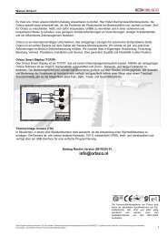
1.2 AIS in an Operational Environment<br />
This illustration depicts a typical AIS System, where two or more AIS<br />
equipped vessels (and shore based systems) are automatically<br />
communicating with each other.<br />
On the bottom, a typical X-PACK DS installation in a common environment is shown. The<br />
X-PACK DS is connected to the vessels emergency power supply, and in connection with<br />
the VHF, and GPS-Antennas, the minimal requirements for Transponder operation are<br />
fulfilled.<br />
Both vessels in the above illustration are equipped with a X-PACK DS (or any other<br />
certified AIS-Transponder). Due to “Time – Synchronization” they use the same<br />
organization of free and allocated windows (Slots) in the shared VHF Data Link (this<br />
method is called “Self Organized Time Division Multiple Access”) to send and receive<br />
messages.<br />
Without the necessity of any active interaction, both vessels know exactly who or what is<br />
cruising nearby and where the individual object is heading.<br />
X-Pack DS <strong>Installation</strong> <strong>Manual</strong> 2 Version 1.0
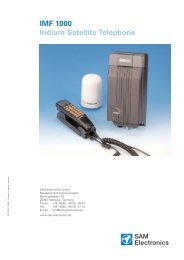
1.3 AIS Networks<br />
The scenario below shows a full AIS coverage area (including all derivates and complete<br />
shore infrastructure).<br />
The Carriage Requirement currently applies exclusively to SOLAS Vessels, but following the<br />
current international discussions on maritime security; it is common understanding that other<br />
possible AIS users will follow very soon. Shore Based infrastructure will be among the first<br />
groups to become AIS equipped.<br />
X-Pack DS <strong>Installation</strong> <strong>Manual</strong> 3 Version 1.0
1.4 Carriage Requirement<br />
1.4.1 Chapter V (Safety of Navigation) Regulation 19, of the SOLAS Convention.<br />
IMO regulations require sea vessels from a size of 300 GT in international and 500 GT in<br />
national waters to be equipped with an AIS-Transponder. The implementation of this<br />
legislation began on 1. July 2002 and will be enforced in the following stages:<br />
• July 2002 for all vessels built from this period onwards<br />
• July 2003 for all passenger ships and all tankers which were built before 1. July 2002<br />
• July 2004 for all ships of 50.000 GT and above which were built before 1. July 2002<br />
• July 2005 for all ships from 10.000 GT up to under 50.000 which were built before<br />
1. July 2002<br />
• July 2006 for all ships from 3.000 GT up to under 10,000 which were built before<br />
1. July 2002<br />
• July 2007 for all ships from 300 GT up to under 3.000 which were built before<br />
1. July 2002<br />
• July 2008 for all other ships which do not travel in international waters and were built<br />
before July 2002<br />
In some cases, exemptions may be granted to such ships, which will be taken off sea within 2<br />
years of legislation coming into effect.<br />
Refer to IMO Recommendation ITU-R M.1371-1 and IALA-AIS-Guidelines<br />
1.4.2 Accelerated Implementation of AIS:<br />
ANNEX<br />
AMENDMENTS TO THE TO THE INTERNATIONAL CONVENTION FOR THE SAFETY OF<br />
LIFE AT SEA, 1974 AS AMENDED CHAPTER V - SAFETY OF NAVIGATION<br />
Regulation 19 - Carriage requirements for ship borne navigational Systems and equipment<br />
states:<br />
1 The existing subparagraphs .4, .5 and .6 of paragraph 2.4.2 are replaced by the<br />
following:<br />
“4 in the case of ships, other than passenger ships and tankers,<br />
of 300 gross tonnage and upwards, but less than 50.000 gross tonnage, not<br />
later than the first safety equipment survey' after 1 July 2004 or by 31<br />
December 2004, whichever occurs earlier; and”<br />
2 The following new sentence has been added at the end of the existing subparagraph<br />
7 of paragraph 2.4;<br />
“Ships fitted with AIS shall maintain AIS in operation at all times except where<br />
international agreements, rules or standards provide for the protection of<br />
navigational information.”<br />
Refer to the International Convention for the Safety of Life at Sea, 1974 (SOLAS), held at<br />
IMO, 9-13 December 2002<br />
X-Pack DS <strong>Installation</strong> <strong>Manual</strong> 4 Version 1.0
2 X-PACK DS<br />
2.1 System Overview<br />
Unlike other AIS devices, the X-PACK DS combines all required functions into one cabinet.<br />
Additionally, the X-PACK DS gives the operator a number of additional features (easy<br />
mounting & installation, environmental protection, smallest dimensions).<br />
X-Pack DS <strong>Installation</strong> <strong>Manual</strong> 5 Version 1.0
3 <strong>Installation</strong><br />
3.1 <strong>Installation</strong> Requirements<br />
General Requirements<br />
Please note that international conventions, regulations, instructions and guidelines have to be<br />
adhered to when installing the X-PACK DS.<br />
The following points must be observed before installation can commence:<br />
- Permission by the local authority to install such a device must be granted.<br />
- Trained service personnel must undertake the installation.<br />
- The X-PACK DS must be fitted in a suitable place on the bridge.<br />
- The VHF and GPS Antennas must be installed in a suitable position, where excellent<br />
reception conditions apply (refer to Chapter 3.10 <strong>Installation</strong> of VHF antenna – page<br />
17)<br />
- All available interfaces must be installed.<br />
- The vessels power supply must suffice, and the GMDSS power supply has to be<br />
used.<br />
- <strong>Installation</strong> of the pilot plug in conning position (close to the pilot working place).<br />
3.2 <strong>Installation</strong> Overview<br />
Survey<br />
AIS is considered part of the ship’s radio station and is surveyed together with radio<br />
installation. Surveys on SOLAS Convention ships should be carried out in accordance with<br />
the rules laid down in IMO Res. A 746(18) "Survey Guidelines under the harmonised system<br />
of survey and certification" (R) 8, and "Protocol of 1988 relating to the International<br />
Convention for the Safety of Life at Sea, 1974."<br />
The X-PACK DS consists of one unit, which integrates all necessary modules.<br />
X-Pack DS <strong>Installation</strong> <strong>Manual</strong> 6 Version 1.0
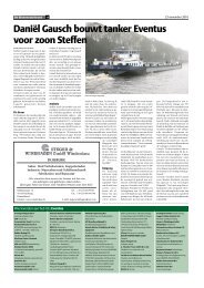
Ground<br />
Step-by-Step <strong>Installation</strong> Procedure:<br />
• Mount the X-PACK DS close to ships operator workstation for traffic surveillance and<br />
maneuvering.<br />
• Use the VHF adapter cable (NAU-B553) together with the VHF plug and TNC plug to<br />
connect the VHF and GPS antenna cables as well as the antennas.<br />
• The sensors, ECDIS, PC, pilot case, long range devices and auxiliary displays can be<br />
connected to the X-PACK DS cabinet by the AIS cable respectively the connection<br />
box. The device is driven by a 24V DC 7A supply, which is connected to the power<br />
terminal at the connection box. The AIS should be connected to an emergency power<br />
source. A battery capacity calculation together with GMDSS-equipment is needed!<br />
Please refer to Appendix 9.1 for examples of battery capacity calculations.<br />
• After performing these steps, the X-PACK DS automatically starts operation.<br />
• The X-PACK DS has a ground terminal which has to be connected to ship ground.<br />
• Now configure the required initial system parameters according to Chapter 4 “Starting<br />
the X-Pack DS” on page 20.<br />
X-PACK DS<br />
NAU-B553<br />
Connection Diagram<br />
Combined Antenna GPS/VHF<br />
NAU-B503<br />
NAU-B620<br />
Fuse<br />
GPS VHF<br />
NAU-B401<br />
Note: The NAUTICAST connection box includes a fuse of 6,3A. If it is not used, then the Unit<br />
has to be protected against high current by an external slow blow fuse of 6,3A!<br />
X-Pack DS <strong>Installation</strong> <strong>Manual</strong> 7 Version 1.0
Components and Interfaces<br />
The diagram below illustrates which devices can be connected to the X-PACK DS. For a<br />
detailed description of sensor connecting e.g. an existing Gyro to the X-PACK DS refer to<br />
Chapter 3 “Sensor <strong>Installation</strong>” on page 13.<br />
3.3 General Interface Description<br />
Interface Designation Speed Direction<br />
Sensor 1 CH 1 4800bps or 38400bps Input<br />
Sensor 2 CH 2 4800bps or 38400bps Input<br />
Sensor 3 CH 3 4800bps or 38400bps Input<br />
ECDIS CH 4 38400bps Input/Output<br />
PILOT CH 5 38400bps Input/Output<br />
LONG RANGE CH 8 38400bps Input/Output<br />
DGPS (RTCM SC104) CH 9 9600bps Input/Output<br />
ALARM CIRCUIT CH 10 Dry relay contact (power off and alarm state closed)<br />
X-Pack DS <strong>Installation</strong> <strong>Manual</strong> 8 Version 1.0
3.4 Interface NMEA Description:<br />
3.4.1 Sensor Interface CH1, CH2, CH3<br />
Sentence Formatters Used Fields<br />
DTM Datum Reference 1<br />
GBS GNSS satellite Fault Detection 1 - 5<br />
GGA Global Positioning System Fix Data 1 - 7; 10<br />
GLL Geographic Position – Latitude/Longitude 1 - 7<br />
GNS GNSS Fix Data 1 - 7<br />
HDT Heading, True 1<br />
OSD Own Ship Data 1 - 6; 9<br />
RMC Recommended Minimum Specific GNSS Data 1 – 6; 9; 12<br />
ROT Rate Of Turn 1 - 2<br />
VBW Dual Ground/Water Speed 4 - 6<br />
VTG Course Over Ground and Ground Speed 1; 5; 7; 9<br />
3.4.2 ECDIS – Presentation Interface CH 4<br />
Sentence Formatters Direction Used Fields<br />
ABK UAIS Addressed and binary broadcast acknowledgement out<br />
ACA AIS Channel assignment message in / out<br />
ACK Acknowledge Alarm in<br />
AIR UAIS Interrogation Request in<br />
ALR Set Alarm State out<br />
ABM UAIS Addressed binary and safety related message in<br />
BBM UAIS Broadcast Binary Message in<br />
DSC Digital Selective Calling Information out<br />
DSE Expanded Digital Selective Calling out<br />
DSI DSC Transponder Initialize out<br />
DSR DSC Transponder Response out<br />
LRI UAIS Long-Range Interrogation out<br />
LRF UAIS Long-Range Function out<br />
SSD Station Static Data in<br />
TXT Text Transmission out<br />
VSD Voyage Static Data in<br />
VDM UAIS VHF Data-link Message out<br />
VDO UAIS VHF Data-link Own-vessel report out<br />
All fields are provided<br />
for Input and Output.<br />
For detailed information<br />
please refer to<br />
IEC 61993-2 / NMEA<br />
0183 HS V3.0 for<br />
detailed field<br />
information.<br />
X-Pack DS <strong>Installation</strong> <strong>Manual</strong> 9 Version 1.0
3.4.3 PILOT Port CH 5<br />
The used sentence Formatters are the same as before described at the ECDIS Port.<br />
Note:<br />
A pilot input/output port is part of an AIS Class A station. A plug connected to this port should<br />
be installed on the bridge near the pilot’s operating position so that a pilot can connect a<br />
Personal Pilot Unit (PPU) if required. Also a power connector for the Pilot Unit should be<br />
available nearby.<br />
The pilot plug should be configured as follows: (Refer to SUB-COMMITTEE ON SAFETY OF<br />
NAVIGATION NAV48/18 2.4.2002)<br />
• AMP/Receptacle (Square Flanged (-1) or Free-Hanging (-2)), Shell size 11, 9-pin,<br />
Std. Sex 206486-1/2 or equivalent with the following terminations:<br />
- Tx A (out-) is connected to Pin 1<br />
- Tx B (out+) is connected to Pin 4<br />
- Rx A (in-) is connected to Pin 5<br />
- Rx B (in+) is connected to Pin 6<br />
- Shield is connected to Pin 9<br />
3.4.4 LONG RANGE CH 8<br />
The AIS long-range function requires a compatible long-range communication system (e.g.<br />
Inmarsat-C or MF/HF radio as part of GMDSS) - a connection between this communication<br />
system and the Class A mobile unit is possible.<br />
This connection is required in order to activate the LR function of the AIS. Its input/output port<br />
must meet the IEC 61162-2 requirements.<br />
Sentence Formatters Direction<br />
LRI UAIS Long Range Interrogation Input<br />
LRF UAIS Long-Range Function Input / Output<br />
LR1 UAIS Long-Range Reply Sentence l Output<br />
LR2 UAIS Long-Range Reply Sentence 2 Output<br />
LR3 UAIS Long-Range Reply Sentence 3 Output<br />
Field Information:<br />
All Fields are provided for Input and Output.<br />
For detailed information please refer to<br />
IEC 61993-2 / NMEA 0183 HS V3.0 for detailed field<br />
information.<br />
X-Pack DS <strong>Installation</strong> <strong>Manual</strong> 10 Version 1.0
3.4.5 DGPS – DGNSS Channel 9<br />
Field / Protocol information:<br />
All Fields are provided, for detailed information please refer to<br />
ITU-R M.823-2 / RTCM SC 104 for detailed field information.<br />
3.4.6 ALARM CIRCUIT – BIIT Channel 10<br />
The AIS requires that an alarm output (relay) must be connected to an audible alarm device<br />
or the ships alarm system, if available.<br />
Alternatively, the BIIT (built-in integrity test) alarm system may use the alarm messages<br />
output on the presentation port (ECDIS Port Channel 5), provided the ECDIS alarm system is<br />
connected and AIS compatible.<br />
3.4.7 Proprietary Sentences<br />
The proprietary NAUTICAST NMEA sentences have the NMEA registered manufacture talker<br />
ID “NAU”. The $PNAU sentences are an addition to the standard sentences and offer other<br />
manufactures full remote control to the transponder. The NMEA Interface developer’s manual<br />
includes the full description of how to use the proprietary NAUTICAST manufacturer<br />
sentences.<br />
List of NAUTICAST related proprietary sentences:<br />
Proprietary NMEA-Sentences $PNAU<br />
MID – Mobile (MMS) Id<br />
ASD – Advanced Ship Data<br />
RCS – Read Configuration Settings<br />
CPW – Check Password<br />
X-Pack DS <strong>Installation</strong> <strong>Manual</strong> 11 Version 1.0
3.5 Sensor notes<br />
External Sensor<br />
The AIS has interfaces (configurable as IEC 61162-1 or 61162-2) for position, bottom track<br />
(BT) speed, heading and rate of turn (ROT) sensors. In general, sensors installed in<br />
compliance with other carriage requirements of SOLAS Chapter V should be connected to<br />
the AIS System.*1. The sensor information transmitted by AIS should be the same<br />
information being used for navigation of the ship. Interfacing problems might occur if the<br />
existing on board sensors do not have serial (IEC 61162) outputs. A converter is needed to<br />
translate the non conform data to IEC 61162 – sensor data. For Example Raytheon Nav<br />
Data Repeater 133-812<br />
*1) The fact that AIS is fitted on board a vessel does NOT entail the need to install additional sensors<br />
other that those stated in the carriage requirements.<br />
External GPS<br />
GNSS position sensors normally have IEC 61162 outputs suitable for direct AIS interfacing.<br />
However, it is important to note that:<br />
• The Geodetic Datum of the position data is transmitted by the sensor in WGS84 so that an<br />
IEC 61162 DTM sentence is configured.<br />
• AIS is able to process two reference points for it’s antenna position, one for external, and<br />
one for an internal sensor. If more than one external reference point is used, the appropriate<br />
information needs to be input to the AIS, so that the reference point information is suitably<br />
adjusted.<br />
External Heading<br />
A gyrocompass providing heading information is a mandatory sensor input to the AIS. A<br />
converter unit (synchro or step-signal converter to NMEA 0183 v.3.0 for example Raytheon<br />
converter type: 133-812) will be needed for AIS connection in the case that the ship’s<br />
gyrocompass does not provide IEC 61162 output.<br />
External Speed and Course<br />
If a bottom track (BT)-log for speed over the ground (SOG) is available, it may be connected.<br />
A converter (for example Raytheon converter type: 133-812) is needed if the BT-log does not<br />
provide IEC 61162 outputs<br />
External Rate of Turn<br />
Not all ships will carry a Rate-Of-Turn (ROT) indicator according to IMO A.526. However, if a<br />
rate-of-turn indicator is available and it includes an IEC 61162 interface, it should be<br />
connected to the AIS.<br />
If ROT information is not available from a ROT indicator, it may (optionally) be derived from<br />
heading information through:<br />
• The gyrocompass itself,<br />
• An external converter unit (see Heading),<br />
• The AIS itself (calculated ROT).<br />
X-Pack DS <strong>Installation</strong> <strong>Manual</strong> 12 Version 1.0
3.6 Sensor <strong>Installation</strong><br />
3.6.1 Signal state definitions<br />
The idle, marking, logical 1, OFF or stop bit state is defined by a negative voltage on line A<br />
with respect to line B, as in IEC 61162-1.<br />
The active, spacing, logical 0, ON or start bit state is defined by a positive voltage on line A<br />
with respect to line B, as in IEC 61162-1.<br />
3.6.2 Talker drive circuits<br />
The drive circuit meets the requirements of ITU-T V.11. The maximum output current is<br />
Imax = 50mA on each port.<br />
3.6.3 Listener receive circuits<br />
Multiple listeners may be connected to a single talker. The listener's receive circuit complies<br />
with ITU-T V.11. Optional termination resistors (120Ohm) for the Input-lines are provided in<br />
the Connection Box. The input terminals A, B and C are electrically isolated from the<br />
remaining electronics of the listening device.<br />
The input impedance is 30kOhm between A and B lines without the termination resistors. The<br />
minimum input voltage is ±0,3V.<br />
3.6.4 Electrical isolation<br />
Within a listener there are no direct electrical connection between the signal lines A and B,<br />
the signal ground C or the shield to ship's mains ground or power line. This isolation is in<br />
accordance with IEC 60945.<br />
3.6.5 Maximum voltage on the bus<br />
The maximum applied voltage between signal lines A and B and between either line and<br />
ground C is in accordance with ITU-T V.11. For protection against miswiring and for<br />
unintended connection to earlier TALKER designs, all receive circuit devices are capable of<br />
withstanding 15 V between both lines and signal ground for an indefinite period.<br />
3.6.6 Data transmission<br />
Data is transmitted in serial asynchronous form in accordance with 1.2. The first bit is a start<br />
bit and is followed by data bits, least-significant-bit first.<br />
The following parameters are used:<br />
– baud rate 38 400 (bits/s) resp. 4 800 (bits/s)<br />
– data bits 8 (D7 = 0), parity none;<br />
– stop bits 1.<br />
X-Pack DS <strong>Installation</strong> <strong>Manual</strong> 13 Version 1.0
3.7 Sensor installation example:<br />
3.7.1 <strong>Installation</strong> of an RS422 serial interface:<br />
Each Interface on the Transponder is a RS422 serial interface!<br />
Shields<br />
A<br />
B<br />
C (GND)<br />
Talker (e.g.: GPS)<br />
3.7.2 Data format:<br />
The talker provides the following data (NMEA 0183 HS V3.0):<br />
$GPDTM,W84,,,,,,,P90*48<br />
$GPGLL,5330.1234,N,01001.2345,E,142555.00,A,A*6A<br />
$GPVTG,350.0,T,,M,10.0,N,,K,A*14<br />
Listener (AIS)<br />
Listener<br />
It is recommended that all three (in this case) NMEA Sentences are provided each second.<br />
The maximal delay is about 5sec.<br />
X-Pack DS <strong>Installation</strong> <strong>Manual</strong> 14 Version 1.0<br />
A<br />
B<br />
C (GND)<br />
A<br />
B<br />
C (GND)
3.8 Pin-Description AIS-Cable / Socket 50-Pins:<br />
TxA � out –<br />
TxB � out +<br />
RxA � in –<br />
RxB � in +<br />
AIS Cable/Socket ( Sub-D 50 Plug )<br />
1 CH5_out+ 34 Spare<br />
18 Ch4_out+<br />
2 CH5_out- 35 Spare<br />
19 CH4_out-<br />
3 CH5_gnd 36 Spare<br />
20 CH4_gnd<br />
4 CH5_in+ 37 Spare<br />
21 CH4_in+<br />
5 CH5_in- 38 Spare<br />
22 CH4_in-<br />
6 CH6_Vin 39 CH9_gnd<br />
23 CH8_in+<br />
7 CH6_gnd 40 CH9_out-<br />
24 CH8_in-<br />
8 CH6_CANL 41 CH9_in-<br />
25 CH8_gnd<br />
9 CH6_CANH 42 CH9_in+<br />
26 CH8_in+<br />
10 CH1_in- 43 CH9_out+<br />
27 CH8_in-<br />
11 CH1_gnd 44 Spare<br />
28 Spare<br />
12 CH1_in+ 45 Spare<br />
29 CH3_in-<br />
13 CH2_in- 46 CH10_1<br />
30 CH3_gnd<br />
14 CH2_gnd 47 CH10_2<br />
31 CH3_in+<br />
15 CH2_in+ 48 Vin_gnd<br />
32 Vin_gnd<br />
16 Vin+ (24V) 49 Vin_gnd<br />
33 Vin+ (24V)<br />
17 Vin+ (24V) 50 Spare<br />
CH1 Sensor CH4 ext. Display CH8 Long Range<br />
CH2 Sensor CH5 aux. Display CH9 DGNSS<br />
BIIT / Relay<br />
CH3 Sensor CH6 opt. 61162-3 CH10 (max. 30V DC / 1A)<br />
Spare Do not use<br />
AIS Plug and Socket<br />
X-Pack DS <strong>Installation</strong> <strong>Manual</strong> 15 Version 1.0
3.9 Pin-Description AIS-Connector:<br />
CH1_in+ 12<br />
CH1_in- 10<br />
CH1_gnd 11<br />
CH2_gnd 14<br />
CH2_in+ 15<br />
CH2_in- 13<br />
CH3_in+ 31<br />
CH3_in- 29<br />
CH3_gnd 30<br />
CH4_gnd 20<br />
CH4_in+ 21<br />
CH4_in- 22<br />
CH4_out+ 18<br />
CH4_out- 19<br />
CH5_in+ 4<br />
CH5_in- 5<br />
CH5_out+ 1<br />
CH5_out- 2<br />
CH5_gnd 3<br />
CH8_gnd 25<br />
CH8_in+ 26<br />
CH8_in- 27<br />
CH8_out+ 23<br />
CH8_out- 24<br />
CH9_in+ 42<br />
CH9_in- 41<br />
CH9_out+ 43<br />
CH9_out- 40<br />
CH9_gnd 39<br />
Spare_gnd 36<br />
Spare_in+ 35<br />
Spare_in- 34<br />
Spare_out+ 38<br />
Spare_out- 37<br />
CH6_CANH 9<br />
CH6_CANL 8<br />
CH6_Vin 6<br />
CH6_gnd 7<br />
BIIT Relais<br />
CH10_1<br />
CH10_2<br />
46<br />
47<br />
Sensor 1,2,3<br />
ECDIS<br />
Pilot Port<br />
Long Range<br />
DGPS<br />
CAN<br />
Note:<br />
TxA � out –<br />
TxB � out +<br />
RxA � in –<br />
RxB � in +<br />
AIS -Cable Sub-D 50 Plug<br />
16<br />
17<br />
33<br />
48<br />
49<br />
32<br />
+ 24 VDC/max 5A rd<br />
+ 24 VDC rd<br />
+ 24 VDC rd<br />
0 V bl<br />
0 V bl<br />
0 V bl<br />
e.g. GPS<br />
GLL, VTG,<br />
DTM<br />
e.g ECDIS<br />
viewer<br />
e.g.<br />
Inmarsat<br />
unit<br />
Service<br />
unit<br />
Alarm unit<br />
SPEED<br />
LOG<br />
VBW<br />
e.g. GYRO<br />
HDT,ROT<br />
RTCM<br />
SC104<br />
NC unit<br />
NC<br />
NC<br />
X-Pack DS <strong>Installation</strong> <strong>Manual</strong> 16 Version 1.0<br />
6<br />
5<br />
4<br />
1<br />
NC<br />
CAN<br />
unit<br />
AMP<br />
Pilot<br />
Plug<br />
Black BK<br />
White WH<br />
Red RD<br />
Green GN<br />
Brown BR<br />
Blue BL<br />
Orange OR<br />
Yellow YL<br />
Violet VI<br />
Gray SL(Slate)<br />
Pink PK<br />
AIS-Cable<br />
Open<br />
1 WH/BK<br />
2 BR/BK<br />
3 SL/GN<br />
7 YL/SL<br />
5 PK/GN<br />
6 YL/PK<br />
9 GN/BL<br />
10 YL/BL<br />
11 GN/RD<br />
17 YL/RD<br />
13 GN/BK<br />
14 YL/BK<br />
15 SL/BL<br />
16 PK/BL<br />
19 SL/RD<br />
20 PK/RD<br />
21 SL/BK<br />
22 PK/BK<br />
23 WH/SL<br />
29 SL/BR<br />
25 WH/PK<br />
26 PK/BR<br />
27 WH/BL<br />
28 BR/BL<br />
31 WH/YL<br />
32 YL/BR<br />
33 WH/GN<br />
34 BR/GN<br />
35 SL/PK<br />
41 RD/BL<br />
37 SL<br />
38 PK<br />
39 GN<br />
40 YL<br />
43 WH<br />
44 BR<br />
45 RD<br />
46 BL<br />
49 BK<br />
50 VI
3.10 <strong>Installation</strong> of VHF / GPS Antennas<br />
Interference to the Ship’s VHF Radiotelephone<br />
The AIS ship borne equipment, like any other ship borne transceiver operating in the VHF<br />
maritime band, may cause interference to a ship’s VHF radiotelephone. Because AIS is a<br />
digital system, this interference may occur as a periodic (e.g. every 20 seconds) soft clicking<br />
sound on the ship’s radiotelephone. This affect may become more noticeable if the VHF<br />
radiotelephone antenna is located close to the AIS VHF antenna, and when the<br />
radiotelephone is operating on channels near the AIS operating channels (e.g. channels 27,<br />
28 and 86).<br />
Attention should be paid to the location and installation of the various antennas, in order to<br />
support the antenna characteristics in the best possible way.<br />
VHF Antenna <strong>Installation</strong><br />
Antenna Location<br />
Location of the mandatory AIS VHF-antenna should be carefully considered. Digital<br />
communication is more sensitive than analogue/voice communication to interference created<br />
by reflections caused by obstructions such as masts and booms. It may be necessary to<br />
relocate the VHF radiotelephone antenna to minimize interference effects.<br />
To minimise interference effects, the following guidelines apply:<br />
• The AIS VHF antenna should have omni directional vertical polarisation providing 3 to 5<br />
dB gain.<br />
• The AIS VHF antenna should be placed in an elevated position, as free standing as<br />
possible, with a minimum of 2 metres in horizontal direction from constructions made of<br />
conductive materials. The antenna should not be installed close to any large vertical<br />
obstruction. The AIS VHF antenna should have a visible sky of 360°.<br />
• The AIS VHF antenna should be installed at least 3 meters away from interfering highpower<br />
energy sources such as radar and other transmitting radio antennas, and out of the<br />
way of the transmitting beam.<br />
• There should not be more than one antenna on each level. The AIS VHF antenna should<br />
be mounted directly above or below the ship’s primary VHF radiotelephone antenna, with<br />
no horizontal separation and a minimum of 2 metres vertical separation. If it is located on<br />
the same level as other antennas, the distance apart should measure at least 10 metres.<br />
• See also sample for antenna layout in Appendix 9.2 (Drawings and Approvals)<br />
Cabling<br />
The cable should be kept as short as possible to minimise attenuation of the signal. Double<br />
shielded coaxial cables equal to or better than RG214 are recommended.<br />
RG214 at VHF attenuation per meter of app. 0,07 dB/m (45m = 3,15db)<br />
VHF AIS frequency app. 162MHz<br />
X-Pack DS <strong>Installation</strong> <strong>Manual</strong> 17 Version 1.0
All outdoor connectors on the coaxial cables should be fitted with preventive isolation, such<br />
as shrink-stocking with silicone to protect the antenna cable against water penetration.<br />
Coaxial cables should be installed in separate signal cable channels/tubes, and at least 10<br />
cm away from any power supply cables. Crossing of cables should take place at right angles<br />
(90°). Coaxial cables should not be exposed to sharp bends, which may lead to changes to<br />
the characteristic impedance of the cable. The minimum bend radius should be 5 times the<br />
cables outside diameter.<br />
Grounding<br />
Coaxial down-leads must be used for all receiving antennas, and the coaxial screen should<br />
be connected to the ground at one end.<br />
GNSS Antenna installation<br />
A Class A AIS must be connected to a GNSS antenna.<br />
Location<br />
The GNSS antenna must be installed where it has a clear view of the sky, so that it accesses<br />
the horizon freely through 360°, with a vertical observation of 5 to 90 degrees above the<br />
horizon. Small diameter obstructions, such as masts and booms, do not seriously impair<br />
signal reception, but such objects must not eclipse more than a few degrees of any given<br />
bearing.<br />
The antenna must be located at least three meters away from, and out of the transmitting<br />
beam of high-power transmitters (S-Band Radar and/or Inmarsat systems). This includes the<br />
ship’s own AIS VHF antenna, if it is designed and installed separately. See also sample for<br />
antenna layout in Appendix 9.2 (Drawings and Approvals)<br />
If a DGNSS system is included or connected to the AIS system, the installation of the<br />
antenna should be undertaken in accordance with IEC 61108-4, Edition 1.<br />
Cabling<br />
To achieve optimum performance, the gain of the antenna pre-amplifier should match the<br />
cable attenuation. The resulting installation gain (pre-amplifier gain - cable attenuation)<br />
should be within 0 to 10 dB.<br />
RG214 at GPS attenuation per meter of app. 0,35 dB/m (45m = 15,75dB)<br />
GPS frequency app. 1,2GHz<br />
The coaxial cable between the antenna and the AIS ship borne station connector should be<br />
routed directly, in order to reduce electromagnetic interference. The cable should not be<br />
installed close to high-power lines, such as radar or radio-transmitter lines, or near the AIS<br />
VHF antenna cable. A space of one meter or more is recommended in order to avoid<br />
degradation due to RF-coupling. Crossing of antenna cables should take place at 90 degrees,<br />
to minimise magnetic field coupling.<br />
X-Pack DS <strong>Installation</strong> <strong>Manual</strong> 18 Version 1.0
Antenna Layout<br />
The position of the VHF und GNSS – antennas must be added to the existing antenna layout<br />
of the vessel.<br />
Power Supply<br />
The X-PACK DS must be supplied from the emergency power source. A further requirement<br />
is to connect AIS to the reserve power source of the GMDSS. A new battery capacity<br />
calculation must then be undertaken. See sample in 9.1 (Samples for battery calculation)<br />
Following documents are needed for the installation approval of the classification<br />
• Antenna Layout (arrangement)<br />
• Battery Calculation<br />
• Connection / Block – Diagram with locations<br />
• Type Approval Certificate<br />
X-Pack DS <strong>Installation</strong> <strong>Manual</strong> 19 Version 1.0
4 Starting the X-PACK DS<br />
After completing the hardware, antennas and external equipment installation, the initial<br />
system start-up can commence. To start the system, connect the X-PACK DS with the power<br />
supply.<br />
The next step is to enter the configuration like password and the MMSI number.<br />
4.1 Service and User Passwords:<br />
The Transponder system is equipped with two separate Passwords.<br />
1) The User Password, which is the lower security level allows access to all menus except<br />
Menu 6: Service Configuration - please refer to the User <strong>Manual</strong> for further details on<br />
password protection.<br />
2) The Service Password is required in order to enter the Service Configuration Menu. This is<br />
a higher security level than can be accessed with the User Password and therefore ensures<br />
that the Service Configuration is protected, and limited to authorized service personnel.<br />
The master of the vessel has to ensure that only authorised persons are allowed to make<br />
changes to the Service Configuration and ensures that the newly reset password is stored<br />
very carefully, as it can not be reset from the default “NAUT” a second time.<br />
A master key is not available.<br />
Changing the Service Password<br />
Select “Service Configuration” from the Main Menu with the cursor button [Up] & [Down] or<br />
press Nr. 6 on the keyboard.<br />
N 1^19' E 0^13' |1>0.01|2>1.30|3>1.80nm<br />
|----------------------------------<br />
| Menu<br />
-----| |<br />
| +- 1. Messages<br />
View | +- 2. AIS Status<br />
| +- 3. Voyage Settings<br />
-----| +- 4. Ship Settings<br />
| +- 5. Transponder Configuration<br />
Msg. | +- 6. Service Configuration<br />
| +- 7. Display Settings<br />
-----|<br />
|<br />
Displ|<br />
----------------------------------------<br />
NUM| Select->| | |
The password query field appears. Input new Service Password and press [Enter].<br />
N 1^24' E 0^17' |1>0.10|2>1.30|3>1.80nm<br />
----------------------------------------<br />
++++++++++++++++++++++++++++++++++++++++<br />
Service password protected!<br />
Please enter service password:<br />
++++++++++++++++++++++++++++++++++++++++<br />
----------------------------------------<br />
| Enter | | | Exit<br />
Select Submenu 1 “Change Service Password” with cursor button [Up] & [Down] by pressing<br />
Nr. 1 on the keyboard.<br />
N 1^21' E 0^14' |1>0.01|2>1.30|3>1.80nm<br />
|----------------------------------<br />
| 6. Service Configuration<br />
-----| |<br />
| +- 1. Change Service Password<br />
View | +- 2. User Password Settings<br />
| +- 3. Change MMSI / IMO<br />
-----| +- 4. Restore Factory Settings<br />
|<br />
Msg. |<br />
|<br />
-----|<br />
|<br />
Displ|<br />
----------------------------------------<br />
NUM| Select->| | |
Enter the new Password:<br />
Repeat the new Password:<br />
A minimum of 4, a maximum of 8 characters are allowed. Should the new password include<br />
numbers, use the shift key to generate them.<br />
Press Save to store the change.<br />
Changing the User Password<br />
N 1^25' E 0^18' |1>0.10|2>1.30|3>1.80nm<br />
******* Change Service Password ********<br />
Enter new password :<br />
Repeat new password:<br />
{Length: 4..8 characters}<br />
----------------------------------------<br />
| Save | | | Back<br />
Select Submenu 2 “User Password Settings” with cursor button [Up] & [Down] by pressing Nr.<br />
2 on the keyboard.<br />
N 1^21' E 0^14' |1>0.01|2>1.30|3>1.80nm<br />
|----------------------------------<br />
| 6. Service Configuration<br />
-----| |<br />
| +- 1. Change Service Password<br />
View | +- 2. User Password Settings<br />
| +- 3. Change MMSI / IMO<br />
-----| +- 4. Restore Factory Settings<br />
|<br />
Msg. |<br />
|<br />
-----|<br />
|<br />
Displ|<br />
----------------------------------------<br />
NUM| Select->| | |
Select Submenu 1 “Change User Password” with cursor button [Up] & [Down] by pressing Nr.<br />
1 on the keyboard.<br />
Enter the new Password:<br />
Repeat the new Password:<br />
A minimum of 4, a maximum of 8 characters are allowed. Should the new password include<br />
numbers, use the shift key to generate them.<br />
Press Save to store the changes.<br />
N 1^21' E 0^14' |1>0.01|2>1.30|3>1.80nm<br />
|----------------------------------<br />
| 6-2. User Password Settings<br />
-----| |<br />
| +- 1. Change User Password<br />
View | +- 2. Change Password Protection<br />
|<br />
-----|<br />
|<br />
Msg. |<br />
|<br />
-----|<br />
|<br />
Displ|<br />
----------------------------------------<br />
NUM| Select->| | |0.10|2>1.30|3>1.80nm<br />
******* Change User Password ***********<br />
Enter new password :<br />
Repeat new password:<br />
{Length: 4..8 characters}<br />
----------------------------------------<br />
| Save | | | Back<br />
X-Pack DS <strong>Installation</strong> <strong>Manual</strong> 23 Version 1.0
4.2 Changing the MMSI / IMO Numbers<br />
Select “Service Configuration” from the Main Menu with the cursor button [Up] & [Down] or<br />
press Nr. 6 on the keyboard.<br />
N 1^19' E 0^13' |1>0.01|2>1.30|3>1.80nm<br />
|----------------------------------<br />
| Menu<br />
-----| |<br />
| +- 1. Messages<br />
View | +- 2. AIS Status<br />
| +- 3. Voyage Settings<br />
-----| +- 4. Ship Settings<br />
| +- 5. Transponder Configuration<br />
Msg. | +- 6. Service Configuration<br />
| +- 7. Display Settings<br />
-----|<br />
|<br />
Displ|<br />
----------------------------------------<br />
NUM| Select->| | |0.01|2>1.30|3>1.80nm<br />
----------------------------------------<br />
++++++++++++++++++++++++++++++++++++++++<br />
Service password protected!<br />
Please enter service password:<br />
++++++++++++++++++++++++++++++++++++++++<br />
----------------------------------------<br />
| Enter | | | Exit<br />
X-Pack DS <strong>Installation</strong> <strong>Manual</strong> 24 Version 1.0
Select Submenu 3 “Change MMSI/IMO” with cursor button [Up] & [Down] by pressing Nr. 3<br />
on the keyboard.<br />
Input new MMSI / IMO Numbers and press [Save] to store input data. Press [Back] to return<br />
to the Submenu without saving.<br />
Note:<br />
Data input is limited to 9 characters.<br />
N 1^21' E 0^14' |1>0.01|2>1.30|3>1.80nm<br />
|----------------------------------<br />
| 6. Service Configuration<br />
-----| |<br />
| +- 1. Change Service Password<br />
View | +- 2. User Password Settings<br />
| +- 3. Change MMSI / IMO<br />
-----| +- 4. Restore Factory Settings<br />
|<br />
Msg. |<br />
|<br />
-----|<br />
|<br />
Displ|<br />
----------------------------------------<br />
NUM| Select->| | | N/A|2>0.00|3>0.10nm<br />
********** Change MMSI / IMO ***********<br />
MMSI :1193046<br />
IMO No.:303174162<br />
----------------------------------------<br />
NUM| Save | | | Back<br />
X-Pack DS <strong>Installation</strong> <strong>Manual</strong> 25 Version 1.0
4.3 Inputing Voyage Related Data – (User Password Protected)<br />
Select “Voyage Settings” from the Main Menu with the cursor button [Up] & [Down]<br />
or press Nr. 3 on the keyboard<br />
Note:<br />
The default User Password is set to “NAUT” – please reconfigure it immediately after<br />
Transponder initial operation<br />
N 1^20' E 0^13' |1> N/A|2>0.00|3>0.10nm<br />
|----------------------------------<br />
| Menu<br />
-----| |<br />
| +- 1. Messages<br />
View | +- 2. AIS Status<br />
| +- 3. Voyage Settings<br />
-----| +- 4. Ship Settings<br />
| +- 5. Transponder Configuration<br />
Msg. | +- 6. Service Configuration<br />
| +- 7. Display Settings<br />
-----|<br />
|<br />
Displ|<br />
----------------------------------------<br />
NUM|Select->| | |0.01|2>1.30|3>1.80nm<br />
----------------------------------------<br />
++++++++++++++++++++++++++++++++++++++++<br />
User password protected!<br />
Please enter user password:<br />
++++++++++++++++++++++++++++++++++++++++<br />
----------------------------------------<br />
| Enter | | | Exit<br />
X-Pack DS <strong>Installation</strong> <strong>Manual</strong> 26 Version 1.0
Scroll the Voyage Data Fields with [Enter] and input own vessel data. Select a default Cargo<br />
Type and NavStat Setting with the cursor buttons [Left] & [Right].<br />
Save the new settings by pressing [Save], and return to the Main Menu Screen by pressing<br />
[Exit]. Press [Back] to return to the Main Menu without saving any changes.<br />
N 1^18' E 0^12' |1>0.01|2>1.30|3>1.80nm<br />
*********** Voyage Settings ************<br />
Cargo :<br />
Draught :24.8m<br />
PoB :1<br />
Dest. :CASABLANCA<br />
ETA :10/13 12:31<br />
NavStat.:Engaged in fishing<br />
----------------------------------------<br />
| Save | | | Back<br />
4.4 Setting Ship Related Data – (User Password Protected)<br />
Select “Ship Settings” with cursor button [Up] & [Down]<br />
or press Nr. 4 on the keyboard.<br />
Note:<br />
The default User Password is set to “NAUT” – please reconfigure it immediately after<br />
Transponder initial operation<br />
N 1^23' E 0^16' |1>0.01|2>1.30|3>1.80nm<br />
|----------------------------------<br />
| Menu<br />
-----| |<br />
| +- 1. Messages<br />
View | +- 2. AIS Status<br />
| +- 3. Voyage Settings<br />
-----| +- 4. Ship Settings<br />
| +- 5. Transponder Configuration<br />
Msg. | +- 6. Service Configuration<br />
| +- 7. Display Settings<br />
-----|<br />
|<br />
Displ|<br />
----------------------------------------<br />
NUM| Select->| | |
N 1^23' E 0^16' |1>0.01|2>1.30|3>1.80nm<br />
----------------------------------------<br />
++++++++++++++++++++++++++++++++++++++++<br />
User password protected!<br />
Please enter user password:<br />
++++++++++++++++++++++++++++++++++++++++<br />
----------------------------------------<br />
| Enter | | | Exit<br />
Scroll the Ship Settings Fields with [Enter] and input own vessel data.<br />
Example: Length = 220m, A = 200m, Beam = 43m, D = 33m<br />
RefPointExt = A200 B20 C10 D33m (location of the external GPS antenna)<br />
A = the distance from bow to the antenna<br />
B= the distance from the antenna to the stern<br />
C = the distance from the port side to the antenna<br />
D = the distance from the antenna to the starboard side<br />
Enter A200D33 (without spaces, no decimals, no commas)<br />
The full line as shown will be displayed: RefPtExt: A200 B20 C10 D33m<br />
B and C are calculated by the AIS.<br />
Enter RetPtInt (location of the internal GPS antenna) in the same way.<br />
Select a default ShipType with the cursor button [Left] & [Right].<br />
Save the new settings by pressing [Save]. Press [Back] return to the Main Menu Screen<br />
without saving any changes.<br />
N 1^19' E 0^12' |1>0.01|2>1.30|3>1.80nm<br />
************ Ship Settings *************<br />
/\ +<br />
CallSign:D11233 / \|<br />
ShipName:ANDREA DORIA | |<br />
Length :220m | A<br />
Beam :43m | x--+<br />
RefPtExt:A200 B20 C10 D33m | | B<br />
RefPtInt:A190 B30 C20 D23m +-C-+D-+<br />
ShipType: Pilot vessel<br />
----------------------------------------<br />
| Save | | | Back<br />
X-Pack DS <strong>Installation</strong> <strong>Manual</strong> 28 Version 1.0
5 Troubleshooting<br />
5.1 Reading and understanding Alarms:<br />
The X-PACK DS differentiates between Alarm and TXT messages. An Alarm informs the user<br />
about major system malfunctions and failings in the connected sensors.<br />
The Alarm Status informs the user about all active Alarms. The Alarm will be disabled and<br />
deleted from the Alarm Status, as soon as the displayed problem has been rectified.<br />
The TXT status displays additional sensor information and the UTC clock status.<br />
See tables (page 30) for Alarm and TXT Messages.<br />
Select “AIS Status” with cursor button [Up] & [Down]<br />
or press Nr. 2 on the keyboard.<br />
N 1^19' E 0^12' |1> N/A|2>0.00|3>0.10nm<br />
|----------------------------------<br />
| Menu<br />
-----| |<br />
| +- 1. Messages<br />
View | +- 2. AIS Status<br />
| +- 3. Voyage Settings<br />
-----| +- 4. Ship Settings<br />
| +- 5. Transponder Configuration<br />
Msg. | +- 6. Service Configuration<br />
| +- 7. Display Settings<br />
-----|<br />
|<br />
Displ|<br />
----------------------------------------<br />
NUM|Select->| | | N/A|2>0.00|3>0.10nm<br />
|----------------------------------<br />
| 2. AIS Status<br />
-----| |<br />
| +- 1. State / Conditions<br />
View | +- 2. Own Ship Data<br />
| +- 3. Own VHF Status<br />
-----| +- 4. Alarm Status<br />
| +- 5. TXT Status<br />
Msg. | +- 6. Version Info<br />
| +- 7. Security Log<br />
-----|<br />
|<br />
Displ|<br />
----------------------------------------<br />
NUM|Select->| | |
5.2 Alarm Codes<br />
ID Description Text Cause/Source<br />
01 AIS: Tx malfunction VHF Antenna,<br />
cabling<br />
02<br />
03<br />
04<br />
05<br />
AIS: Antenna VSWR<br />
exceeds limit<br />
(VSWR - Voltage<br />
Standing Wave Ratio)<br />
AIS: Rx channel 1<br />
malfunction<br />
AIS; Rx channel 2<br />
malfunction<br />
AIS: Rx channel 70<br />
malfunction<br />
VHF antenna,<br />
installation<br />
Internal error<br />
06 AIS: General failure Internal error<br />
25<br />
26<br />
29<br />
AIS; External EPFS lost<br />
(EPFS = electronic<br />
Position Fixing System<br />
such as GPS)<br />
AIS: No sensor position<br />
in use<br />
AIS: No valid SOG<br />
information<br />
30 AIS: No valid COG<br />
Information<br />
32<br />
35<br />
No valid data on<br />
Ch1, Ch2 or Ch3<br />
is available<br />
No valid position<br />
from internal GPS<br />
or external<br />
position sensor<br />
No valid data from<br />
external speed<br />
sensor or internal<br />
GPS<br />
No valid data from<br />
external sensor or<br />
internal GPS<br />
AIS: Heading lost/invalid No valid data from<br />
external sensor<br />
(Gyrocompass)<br />
AIS: No valid ROT<br />
Information<br />
No ROT indicator<br />
is used.<br />
No valid data from<br />
external sensor<br />
System Reaction / Remedy<br />
Reaction: The transponder unit stops transmission. If Alarm ID 01 and<br />
ID 02 are simultaneously displayed, then a major antenna problem has<br />
arisen.<br />
Remedy:<br />
Check if the antenna is AIS compatible (156-162 MHz) and if the<br />
antenna cabling has a short circuit or is missing any contacts at the<br />
connectors.<br />
If the ID 01 is displayed as a stand alone message, then the unit<br />
requires replacing.<br />
Reaction: The transponder unit continues transmission.<br />
Remedy:<br />
Check the antenna and the antenna cabling (RG214 / 50 Ohm cable<br />
required).<br />
Reaction: The transponder unit stops transmission on the affected<br />
channel,<br />
Remedy;<br />
If this alarm reoccurs regularly, then the transponder unit requires<br />
replacing.<br />
Reaction: The transponder unit stops transmission.<br />
Remedy;<br />
The transponder unit requires replacing.<br />
Reaction: The transponder unit continues operation using the position<br />
data of the internal GPS. If there is no valid position data available from<br />
the internal GPS, error 026 is additionally displayed.<br />
Remedy:<br />
Id 25 indicates that the sentences GLL, GNS, GGA, RMC cannot be<br />
received. Check the sensor and the cabling; check if the system that<br />
delivers the data is working. Check the baud rate settings of the sensor<br />
inputs. AIS requires the protocol NMEA 0183 V3.0!<br />
Reaction: The transponder unit continues operation.<br />
Remedy:<br />
Check the sensor cabling and the antenna of the internal GPS sensor.<br />
Reaction: The transponder unit continues operation and displays SOG:<br />
N/A<br />
Remedy;<br />
The sentences VBW, VTG, RMC cannot be received. Check the<br />
sensor and the cabling; check if the system that delivers the data is<br />
working. Check the baud rate settings of the sensor inputs. AIS<br />
requires the protocol NMEA 0183 V3.0!<br />
Reaction: The transponder unit continues operation and displays COG:<br />
N/A<br />
Remedy:<br />
The sentences VBW, VTG, RMC cannot be received. Check the sensor<br />
and the cabling, check if the system that delivers the data is working.<br />
Check the baud rate settings of the sensor inputs. AIS requires the<br />
protocol NMEA 0183 V3.0!<br />
Reaction: The transponder unit continues operation<br />
Remedy:<br />
The sentence for HDT cannot be received. Check the sensor and the<br />
cabling, check if the system that delivers the data is working. Check the<br />
baud rate settings of the sensor inputs. Mention AIS accepts true<br />
heading only (no magnetic).<br />
Reaction: The transponder unit continues operation<br />
Remedy:<br />
The sentence for ROT cannot be received. If a Rate Of Turn indicator is<br />
not in use, then it suffices to just acknowledge the alarm. The Alarm<br />
Status will store the information that no ROT sensor is available.<br />
Otherwise, check the sensor and the cabling. Check if the system that<br />
delivers the data is working. Check the baud rate settings of the sensor<br />
inputs. AIS requires the protocol NMEA 0183 V3.0!<br />
X-Pack DS <strong>Installation</strong> <strong>Manual</strong> 30 Version 1.0
5.3 Text Messages<br />
ID Description Text Cause/Source<br />
07 AIS: UTC clock lost<br />
21<br />
22<br />
23<br />
24<br />
AIS: external DGNSS in<br />
use<br />
AIS: external GNSS in<br />
use<br />
AIS: internal DGNSS in<br />
use (beacon) 023<br />
AIS: internal DGNSS in<br />
use (message 17)<br />
25 AIS: internal GNSS in<br />
use<br />
27<br />
28<br />
31<br />
33<br />
34<br />
AIS: external SOG/COG<br />
in use<br />
AIS: internal SOG/COG<br />
in use<br />
Internal GPS<br />
Information<br />
Information<br />
Information<br />
Information<br />
additional to Alarm<br />
ID 25<br />
Information<br />
Information<br />
additional to Alarm<br />
ID 29 or ID 30<br />
Reaction of the System / Remedy<br />
Reaction: the transponder unit continues operation using indirect or<br />
semaphore synchronisation<br />
Remedy:<br />
Check GPS Antenna for AIS.<br />
Reaction: Positioning is fully operational<br />
Remedy: no action required<br />
Reaction: The transponder unit continues operation using the position<br />
data from a GNSS receiver<br />
Remedy: no action required<br />
Reaction: The transponder unit uses position data from the internal<br />
source. The internal GNSS receiver is capable of processing DGNSS<br />
corrections.<br />
Remedy: no action required<br />
Reaction: The transponder unit continues operation using the position<br />
data from the internal GPS.<br />
Remedy<br />
Check the sensor and the cabling; Check if the system that delivers the<br />
data is working; Check the baud rate settings of the sensor input<br />
Reaction: COG/SOG is in full operation<br />
Remedy: no action required<br />
Reaction: The transponder unit continues operation using the data<br />
from the internal GPS.<br />
Remedy<br />
Check the sensor and the cabling; Check if the system that delivers the<br />
data is working; Check the baud rate settings of the sensor inputs<br />
AIS: Heading valid Information Reaction: Heading is in full operation<br />
Remedy: no action required<br />
AIS: Rate of Turn<br />
Indicator in use<br />
AIS: Other ROT source<br />
in use<br />
Information<br />
Reaction: A Rate Of Turn indicator is connected and in full operation<br />
Remedy: no action required<br />
Information Reaction: The transponder unit is operating with ROT data rather than<br />
with TIROT data - therefore the AIS only differs between + 127 (turning<br />
right at 720 degrees per minute or higher) and – 127 ( turning<br />
left at 720 degrees per minute or higher)<br />
X-Pack DS <strong>Installation</strong> <strong>Manual</strong> 31 Version 1.0
6 Accessories<br />
The following material is included to the X-PACK DS.<br />
X-PACK DS<br />
Basic Kit<br />
includes<br />
1 X-PACK DS Transponder<br />
1 CD with demo software and documentation<br />
1 installation manual, 1 user <strong>Manual</strong>, 1 quick user manual<br />
3 caps of plug<br />
1 cable clamp (M5 thread)<br />
1 guide plate Kit<br />
3 angles + 3 mounting screws (screw bolt + square nut)<br />
NAU-A1<br />
The X-PACK DS is supplied with some of the components listed below (contents depend on<br />
customer requirements).<br />
Category<br />
Mountings:<br />
GPS antenna solutions:<br />
VHF antenna solutions:<br />
Single antenna solutions :<br />
Cables and interfaces:<br />
Description Order Number<br />
Kit bracket-mounting + 2 wing bolts + 4 screws NAU-D503<br />
Mounting kit retro fit-frame + 3 screws, 3 clips, 3 nuts NAU-D500<br />
19" frame + 3 mounting screws (screw bolt + square nut) NAU-D502<br />
Matsushita GPS antenna marine II NAU-X6011<br />
Mounting for GPS-antenna Marine II plastic NAU-X6012<br />
Mounting for GPS-antenna Marine II metal NAU-X6013<br />
Procom GPS antenna GPS 4 NAU-B602<br />
Glomex VHF antenna RA 109 sls + mounting kit NAU-B610<br />
Comrod VHF antenna AV 7 + mounting kit NAU-B611<br />
Procom VHF antenna CLX 2-1 + mounting kit NAU-B612 + NAU-X6022<br />
Comrod AC 17 - AIS (combined GPS/VHF antenna)<br />
+ mounting kit<br />
+ splitter and cable<br />
GPS / VHF extender with N and TNC connection<br />
NAU–B620<br />
+ N(m)/RG214 crimp<br />
+ TNC(m)/RG214 crimp<br />
NAU-B553<br />
AIS connection box NAU-B401<br />
AIS cable open (3m) with all interfaces<br />
+ pilot plug<br />
NAU-B503<br />
Connector N(m)/RG214 crimp NAU-X5531<br />
Connector PL(m)/RG214 crimp NAU-X5533<br />
Connector TNC(m)/RG214 crimp NAU-X5534<br />
Gyro Converter 9028C NAU-Z002<br />
X-Pack DS <strong>Installation</strong> <strong>Manual</strong> 32 Version 1.0
7 Technical Information<br />
PHYSICAL<br />
Size in mm (w) 201,26<br />
Size in mm (h) 60<br />
Size in mm (d) 281,26<br />
Weight 2490 g<br />
Operating Temperature (Celsius) -15° to +55°<br />
POWER SUPPLY<br />
Supply Voltage (galvanic isolated) 24 V DC (-10% +30%)<br />
Input Current min.7 A (24V)<br />
INTERFACES<br />
Number of Data Ports 3 Input / 4 I-O / 1 Output<br />
IEC 61162-1/2 ( RS422 / NMEA 0183)<br />
ITU-R M.823-2 ( RS422 / RTCM SC104)<br />
Bitrate 4800 bps / 38400 bps<br />
Sensor (Input; i.E.: GPS)<br />
Sensor (Input; i.E.: GYRO)<br />
Sensor (Input; i.E.: HDG)<br />
Pilot Port (In- / Output) AIS targets, AIS messages<br />
ECDIS Port (In- / Output) AIS targets, AIS messages<br />
Long Range Port (In- / Output)<br />
DGPS correction (In- / Output) DGPS (RTCM SC104)<br />
BUILT IN GPS<br />
Receiver Architecture 12 channel differential<br />
Tracking Capability 12 satellites sim.<br />
Accuracy Horizontal 10m (2drms) *<br />
Accuracy Vertical 15m (2drms) *<br />
GPS Antenna Connector TNC<br />
DGPS Accuracy < 5m (2drms)<br />
*) depends on SA<br />
GPS Solutions<br />
Beacon interoperability<br />
EGNOS interoperability<br />
WAAS interoperability<br />
OMNISTAR interoperability<br />
LongWave interoperability<br />
VHF interop. (DGPS over Msg.17)<br />
optional internal Beacon Receiver<br />
Combined GPS/DGPS Antenna<br />
BIIT – Alarm System<br />
Relay breaking capacity<br />
30V DC 8A<br />
250V AC 8A<br />
OPTIONAL INTERFACES<br />
Number of Data Ports RS232<br />
Bitrate<br />
Simplex / Duplex<br />
Number of Data Ports IEC<br />
61162-3 CAN (RS485)<br />
Bitrate<br />
up to 5<br />
Up to 115000 bps<br />
Duplex<br />
1<br />
up to 1 Mbps<br />
KEYBOARD<br />
Integrated alphanumerical<br />
SPECIFIED STANDARDS<br />
IMO MSC.74(69) Annex 3<br />
ITU-R M.1371 (Class A)<br />
IALA Techn.Clar. of ITU-R M.1371-1<br />
(Ed.1.3)<br />
IEC 61993-2 (2002)<br />
IEC 61162-1 (2000) NMEA 0183-3<br />
IEC 61162-2 (1998) NMEA 0183-3<br />
IEC 61162-3 NMEA 2000<br />
ITU-R M.823-2<br />
IEC 61108-1 (1996)<br />
IEC 60 945 (1996)<br />
ITU-R M.825-3<br />
ITU-R M.1084-3<br />
VHF<br />
Frequency Range 156 MHz - 162MHz<br />
Channel Spacing 12.5 or 25kHz<br />
Number of RF Channels 3 Receiv. / 1 Transm.<br />
Number of AIS Receivers 2<br />
Number of DSC Receivers 1<br />
Frequency Error<br />
+/- 2.5ppm<br />
VHF TRANSMITTER<br />
2 Watt to 12.5 Watt<br />
Output Power<br />
(adjustable)<br />
Receive to Transmit Switching Time < 1ms<br />
Transmit release time < 1ms<br />
Automatic shutdown 1 sec.<br />
Channel switching time < 25ms<br />
Attack Time < 1ms<br />
VHF RECEIVER<br />
Max. Useable Sensitivity < -110dBm<br />
Co-channel Rejection > -8dB (25kHz);<br />
> -12dBm (12.5kHz)<br />
Adjacent Channel Selectivity > 70dB (25kHz);<br />
> 60dB (12.5kHz)<br />
Inter-modulation Rejection > 65dB<br />
Spurious Response Rejection > 70dB<br />
Blocking > 84dB<br />
VHF MODEM<br />
Bitrate GMSK 9600 bps<br />
RF Baud Rate (DSC) 1200bps<br />
Modulation GMSK / FSK<br />
SOFTWARE<br />
X-PACK DS Version 2.0.x<br />
- installed and ready for use<br />
- implemented configuration Software<br />
- User friendly Interface<br />
to System and AIS Information<br />
- additional Interface to System<br />
Configuration<br />
(Windows 2000 ® )<br />
- X-PACK DS Demonstrator<br />
for training purposes<br />
(Windows 2000 ® )<br />
HARDWARE<br />
X-PACK DS Version 1.0.x<br />
DISPLAY<br />
Integrated<br />
graphical 240 x 128<br />
adjustable brightness<br />
and contrast<br />
X-Pack DS <strong>Installation</strong> <strong>Manual</strong> 33 Version 1.0
8 Contact and Support Information<br />
Please contact your local <strong>Nauticast</strong> Dealer for technical support, and refer to the<br />
<strong>Nauticast</strong> Website http://www.nauticast.com/index.php?id=200 for Dealer and Service<br />
Network Listings.<br />
<strong>Nauticast</strong> Dealers and Service Partners can send a Problem Report to <strong>Nauticast</strong> AG<br />
http://www.nauticast.com/index.php?id=192<br />
<strong>Nauticast</strong> AG<br />
Mariahilfer Strasse 50/2/11<br />
A-1070 Vienna<br />
Austria<br />
Tel: +43-1-5237 237-0<br />
Fax: +43-1-5237 237-150<br />
Email: Technical.Support@nauticast.com<br />
Web: www.<strong>Nauticast</strong>.com<br />
Forms for Problem Report or <strong>Installation</strong> Checklist can be found on the CD-ROM.<br />
X-Pack DS <strong>Installation</strong> <strong>Manual</strong> 34 Version 1.0
Sample for battery Calculation<br />
GMDSS Reserve Battery Calculation ( 24 V DC )<br />
According to IMO Regulation COMSAR/Circ.16 4. March 1998<br />
A: with Emergency Generator ( SOLAS IV 13.2 )<br />
The GMDSS equipment shall be able to operate one (1) hour on reserve power<br />
With 50% of time in transmission mode and 50% in receiving mode.<br />
B: without Emergency Generator ( SOLAS IV 13.2 )<br />
The GMDSS equipment shall be able to operate six (6) hours on reserve power<br />
with 50% of time in transmission mode and 50 % of receiving mode.<br />
Equipment Type Transmitting Receiving Additional<br />
MF/HF STR 2000 18,75 A 4 A incl.DSC<br />
Inmarsat C STR 1500 CN 5 A 1,8 A incl.EGC<br />
VHF 1 with DSC VHF1000DSC 6,5 A 0,65 A incl.DSC<br />
VHF 2 with DSC VHF1000DSC 6,5 A 0,65 A incl.DSC<br />
AIS AIS - Unit 5,0 A 1,0A<br />
Emergency Light 2,5 A<br />
Total 41,75 A 8,1 A 2.5 A<br />
Calculation:<br />
Case A:<br />
1h x ( 0.5 I TX + I RX + I Add ) x 1.4 = 44.06 Ah<br />
recommend battery capacity is 86 Ah<br />
Charger:<br />
I Charg x 0.1 I Batt/h = 8.6 A<br />
recommend charger is type 20 A<br />
Case B:<br />
6h x ( 0.5 I TX + I RX + I Add ) x 1.4 = 264.39 Ah<br />
The battery calculation should not be used for uninterruptible power supply (UPS)<br />
configuration
Sample for battery calculation<br />
GMDSS Reserve Battery Calculation ( 24 V DC )<br />
According to IMO Regulation COMSAR/Circ.16 4. March 1998<br />
A: with Emergency Generator ( SOLAS IV 13.2 )<br />
The GMDSS equipment shall be able to operate one (1) hour on reserve power<br />
With 50% of time in transmission mode and 50% in receiving mode.<br />
B: without Emergency Generator ( SOLAS IV 13.2 )<br />
The GMDSS equipment shall be able to operate six (6) hours on reserve power<br />
with 50% of time in transmission mode and 50 % of receiving mode.<br />
Equipment Type Transmitting Receiving Additional<br />
MF/HF STR 2000 R 15 A 4 A incl.DSC<br />
Inmarsat C STR 1500 CN 5 A 1,8 A incl.EGC<br />
VHF 1 with DSC VHF1000DSC 6,5 A 0,65 A incl.DSC<br />
VHF 2 with DSC VHF1000DSC 6,5 A 0,65 A incl.DSC<br />
AIS AIS - Unit 5,0 A 1,0 A<br />
Emergency Light 2,5 A<br />
Total 38 A 8,1 A 2.5 A<br />
Calculation:<br />
Case A:<br />
1h x ( 0.5 I TX + I RX + I Add ) x 1.4 = 41.44 Ah<br />
recommend battery capacity is 86 Ah<br />
Charger:<br />
I Charge x 0.1 I Batt/h = 8.6 A<br />
recommend charger is type 20 A<br />
Case B:<br />
6h x ( 0.5 I TX + I RX + I Add ) x 1.4 = 248.66 Ah<br />
The battery calculation should not be used for uninterruptible power supply (UPS)<br />
configuration
9.2 Drawings and Approvals<br />
These documents are encluded on the following pages:<br />
(1) Dimensional Drawings<br />
(2) Type Approvals<br />
(3) Connection Drawings<br />
(4) Antenna Layout<br />
(5) Sample for data telegrams<br />
X-Pack DS <strong>Installation</strong> <strong>Manual</strong> 37 Version 1.0
EG - Konformitätserklärung<br />
CE - Declaration of Conformity<br />
Diese Konformitätserklärung bestätigt, dass das unten benannte Produkt den Auflagen der EC Council Directive<br />
96/98/EC vom 20 Dezember 1996 für maritime Ausrüstung, geändert durch die EC Council Directive 2002/75/EC vom 2.<br />
September 2002 entspricht und von der benannten Stelle Nr. 0735 (BSH) typengeprüft ist.<br />
This declaration of conformity certified that the mentioned equipment is in compliance with EC Council Directive<br />
96/98/EC of 20 December 1996 on Marine Equipment, last amended by EC Council Directive 2002/75/EC of 2<br />
September 2002 and has been type examined by the Notified Body No. 0735 (BSH).<br />
Produktbezeichnung:<br />
name of product<br />
OEM Name:<br />
Trade Name<br />
Zertifikate der benannten<br />
Stelle Nr. 0735 (BSH):<br />
Certificates from the<br />
notified Body No. 0735 (BSH)<br />
Spezifizierte Standards:<br />
Specified Standard(s)<br />
Dokument- Nr.:<br />
document-no :<br />
Jahr, Monat:<br />
Year, month:<br />
2004/001<br />
2004/01<br />
X-Pack DS<br />
Annex A1 Item: 4.32 Automatic Identification System (AIS)<br />
RM 808 AIS<br />
EC Type Examination (Module B) Certificate<br />
734.2/0051-1/2003<br />
EC Quality System (Module D) Certificate<br />
BSH-052-03-2003<br />
IMO MSC.74(69) Annex 3<br />
ITU-R M.1371-1 (Class A)<br />
IALA Technical Clarifications of Rec.<br />
ITU-R M.1371-1 (Edition 1.3)<br />
ITU-R M.825-3<br />
ITU-R M1084-3<br />
Hersteller: <strong>Nauticast</strong> Schiffsnavigationssysteme AG<br />
manufacturer<br />
Anschrift: Mariahilfer Straße 50/2/11<br />
address 1070 Wien, Austria<br />
Aussteller: Technischer Leiter<br />
Issuer Chief Technology Officer<br />
Ort, Datum: Vienna, 2004-01-01<br />
place, date<br />
Unterschrift:<br />
signature<br />
ISO 9001:2000 Zertifizierung / ISO 9001:2000 Certification<br />
<strong>Nauticast</strong> hat ein Qualitätsmanagement System nach ISO 9001:2000 implementiert, und ist seit Juli 2003 ISO-zertifiziert.<br />
<strong>Nauticast</strong> maintains a Quality Management System according to ISO 9001:2000, and received ISO certification in July 2003.<br />
IEC 61993-2 (2002)<br />
IEC 61162-1 (2000), -2 (1998)<br />
IEC 60945 (1996)<br />
IEC 61108-1 (1996)<br />
Diese Erklärung bescheinigt die Übereinstimmung mit den genannten Richtlinien, ist jedoch keine Zusicherung von Eigenschaften.<br />
Die Sicherheitshinweise der mitgelieferten Produktdokumentation sind zu beachten.<br />
This declaration certifies the compliance with the indicated directives but implies no warranty of properties.<br />
The safety instructions of the accompanying product documentation shall be observed.<br />
EG-Konformitätserklärung Nr.: 2004/001 page 1 of 1 CE Conformity X-Pack DS.doc<br />
EC-Declaration of conformity N°:
Konformitätserklärung<br />
Declaration of Conformity<br />
Konformitätserklärung<br />
Declaration of Conformity<br />
Diese Konformitätserklärung bestätigt, dass das unten benannte Zubehör gleich oder besser dem im untenstehenden<br />
Zertifikat ausgewiesenen Zubehör ist.<br />
This declaration of conformity certifies that the mentioned accessory is equal or better to the equipment stated in the<br />
beyond Certificate.<br />
X-Pack DS<br />
Automatic Identification System (AIS)<br />
Produktbezeichnung:<br />
name of product<br />
X-Pack DS<br />
Automatic Identification System (AIS)<br />
Produktbezeichnung:<br />
name of product<br />
RM 808 AIS<br />
OEM Name:<br />
Trade Name<br />
RM 808 AIS<br />
OEM Name:<br />
Trade Name<br />
EC Type Examination (Module B) Certificate<br />
734.2/0051-1/2003<br />
EC Type Examination (Module B) Certificate<br />
734.2/0051-1/2003<br />
EC Quality System (Module D) Certificate<br />
BSH-052-03-2003<br />
Zertifikate der benannten<br />
Stelle Nr. 0735 (BSH):<br />
Certificates from the<br />
notified Body No. 0735 (BSH)<br />
EC Quality System (Module D) Certificate<br />
BSH-052-03-2003<br />
Zertifikate der benannten<br />
Stelle Nr. 0735 (BSH):<br />
Certificates from the<br />
notified Body No. 0735 (BSH)<br />
IEC 61993-2 (2002)<br />
IEC 61162-1 (2000), -2 (1998)<br />
IEC 60945 (1996)<br />
IEC 61108-1 (1996)<br />
IMO MSC.74(69) Annex 3<br />
ITU-R M.1371-1 (Class A)<br />
IALA Technical Clarifications of Rec.<br />
ITU-R M.1371-1 (Edition 1.3)<br />
ITU-R M.825-3<br />
ITU-R M1084-3<br />
Spezifizierte Standards:<br />
Specified Standard(s)<br />
Zubehörtyp :<br />
VHF Antenna PROCOM<br />
Type of Accessory<br />
Procom CXL 2-1 VHF Antenna<br />
<strong>Nauticast</strong> Part.No. NAU-B 612<br />
Einschränkungen / Hinweise :<br />
verlegte Kabellänge < 40 m<br />
Restrictions / Comments<br />
installed Cable length < 40m<br />
Combined GPS/VHF Antenna COMROD<br />
Zubehörtyp :<br />
Comrod AC17/2 combined GPS/VHF Antenna +<br />
Type of Accessory<br />
Splitter (in Cable integrated)<br />
<strong>Nauticast</strong> Part.No. NAU-B 620<br />
Einschränkungen / Hinweise :<br />
verlegte Kabellänge < 40 m<br />
Restrictions / Comments<br />
installed Cable length < 40m<br />
2004/006<br />
Dokument- Nr.:<br />
document-no :<br />
2004/002<br />
Dokument- Nr.:<br />
document-no :<br />
2004/02<br />
Jahr, Monat:<br />
Year, month:<br />
2004/02<br />
Jahr, Monat:<br />
Year, month:<br />
Hersteller: <strong>Nauticast</strong> Schiffsnavigationssysteme AG<br />
manufacturer<br />
Hersteller: <strong>Nauticast</strong> Schiffsnavigationssysteme AG<br />
manufacturer<br />
Anschrift: Mariahilfer Straße 50/2/11<br />
address 1070 Wien, Austria<br />
Anschrift: Mariahilfer Straße 50/2/11<br />
address 1070 Wien, Austria<br />
Aussteller: Technischer Leiter<br />
Issuer Chief Technology Officer<br />
Aussteller: Technischer Leiter<br />
Issuer Chief Technology Officer<br />
Ort, Datum: Vienna, 2004-02-19<br />
place, date<br />
Ort, Datum: Vienna, 2004-02-19<br />
place, date<br />
Unterschrift:<br />
signature<br />
Unterschrift:<br />
signature<br />
ISO 9001:2000 Zertifizierung / ISO 9001:2000 Certification<br />
<strong>Nauticast</strong> hat ein Qualitätsmanagement System nach ISO 9001:2000 implementiert, und ist seit Juli 2003 ISO-zertifiziert.<br />
<strong>Nauticast</strong> maintains a Quality Management System according to ISO 9001:2000, and received ISO certification in July 2003.<br />
Diese Erklärung bescheinigt die Übereinstimmung mit den genannten Richtlinien, ist jedoch keine Zusicherung von Eigenschaften.<br />
Die Sicherheitshinweise der mitgelieferten Produktdokumentation sind zu beachten.<br />
This declaration certifies the compliance with the indicated directives but implies no warranty of properties.<br />
The safety instructions of the accompanying product documentation shall be observed.<br />
EG-Konformitätserklärung Nr.: 2004/006 page 1 of 1 Antenna ProcomCXL 2-1 Conformity_006.doc<br />
EC-Declaration of conformity N°:<br />
EG-Konformitätserklärung Nr.: 2004/002 page 1 of 1 Combined Antenna Comrod Conformity.doc<br />
EC-Declaration of conformity N°:
Konformitätserklärung<br />
Declaration of Conformity<br />
Konformitätserklärung<br />
Declaration of Conformity<br />
Diese Konformitätserklärung bestätigt, dass das unten benannte Zubehör gleich oder besser dem im untenstehenden<br />
Zertifikat ausgewiesenen Zubehör ist.<br />
This declaration of conformity certifies that the mentioned accessory is equal or better to the equipment stated in the<br />
beyond Certificate.<br />
Diese Konformitätserklärung bestätigt, dass das unten benannte Zubehör gleich oder besser dem im untenstehenden<br />
Zertifikat ausgewiesenen Zubehör ist.<br />
This declaration of conformity certifies that the mentioned accessory is equal or better to the equipment stated in the<br />
beyond Certificate.<br />
X-Pack DS<br />
Automatic Identification System (AIS)<br />
Produktbezeichnung:<br />
name of product<br />
X-Pack DS<br />
Automatic Identification System (AIS)<br />
Produktbezeichnung:<br />
name of product<br />
RM 808 AIS<br />
OEM Name:<br />
Trade Name<br />
RM 808 AIS<br />
OEM Name:<br />
Trade Name<br />
EC Type Examination (Module B) Certificate<br />
734.2/0051-1/2003<br />
EC Type Examination (Module B) Certificate<br />
734.2/0051-1/2003<br />
EC Quality System (Module D) Certificate<br />
BSH-052-03-2003<br />
Zertifikate der benannten<br />
Stelle Nr. 0735 (BSH):<br />
Certificates from the<br />
notified Body No. 0735 (BSH)<br />
EC Quality System (Module D) Certificate<br />
BSH-052-03-2003<br />
Zertifikate der benannten<br />
Stelle Nr. 0735 (BSH):<br />
Certificates from the<br />
notified Body No. 0735 (BSH)<br />
IEC 61993-2 (2002)<br />
IEC 61162-1 (2000), -2 (1998)<br />
IEC 60945 (1996)<br />
IEC 61108-1 (1996)<br />
IMO MSC.74(69) Annex 3<br />
ITU-R M.1371-1 (Class A)<br />
IALA Technical Clarifications of Rec.<br />
ITU-R M.1371-1 (Edition 1.3)<br />
ITU-R M.825-3<br />
ITU-R M1084-3<br />
Spezifizierte Standards:<br />
Specified Standard(s)<br />
IEC 61993-2 (2002)<br />
IEC 61162-1 (2000), -2 (1998)<br />
IEC 60945 (1996)<br />
IEC 61108-1 (1996)<br />
IMO MSC.74(69) Annex 3<br />
ITU-R M.1371-1 (Class A)<br />
IALA Technical Clarifications of Rec.<br />
ITU-R M.1371-1 (Edition 1.3)<br />
ITU-R M.825-3<br />
ITU-R M1084-3<br />
Spezifizierte Standards:<br />
Specified Standard(s)<br />
VHF Antenna COMROD<br />
Zubehörtyp :<br />
Comrod AV-7 VHF Antenna<br />
Type of Accessory<br />
<strong>Nauticast</strong> Part.No. NAU-B 611<br />
Einschränkungen / Hinweise :<br />
verlegte Kabellänge < 40 m<br />
Restrictions / Comments<br />
installed Cable length < 40m<br />
Zubehörtyp :<br />
VHF Antenna PROCOM<br />
Type of Accessory<br />
Procom CXL 2-1 VHF Antenna<br />
<strong>Nauticast</strong> Part.No. NAU-B 612<br />
Einschränkungen / Hinweise :<br />
verlegte Kabellänge < 40 m<br />
Restrictions / Comments<br />
installed Cable length < 40m<br />
2004/006<br />
Dokument- Nr.:<br />
document-no :<br />
2004/004<br />
Dokument- Nr.:<br />
document-no :<br />
2004/02<br />
Jahr, Monat:<br />
Year, month:<br />
2004/02<br />
Jahr, Monat:<br />
Year, month:<br />
Hersteller: <strong>Nauticast</strong> Schiffsnavigationssysteme AG<br />
manufacturer<br />
Hersteller: <strong>Nauticast</strong> Schiffsnavigationssysteme AG<br />
manufacturer<br />
Anschrift: Mariahilfer Straße 50/2/11<br />
address 1070 Wien, Austria<br />
Anschrift: Mariahilfer Straße 50/2/11<br />
address 1070 Wien, Austria<br />
Aussteller: Technischer Leiter<br />
Issuer Chief Technology Officer<br />
Aussteller: Technischer Leiter<br />
Issuer Chief Technology Officer<br />
Ort, Datum: Vienna, 2004-02-19<br />
place, date<br />
Ort, Datum: Vienna, 2004-02-19<br />
place, date<br />
Unterschrift:<br />
signature<br />
Unterschrift:<br />
signature<br />
ISO 9001:2000 Zertifizierung / ISO 9001:2000 Certification<br />
<strong>Nauticast</strong> hat ein Qualitätsmanagement System nach ISO 9001:2000 implementiert, und ist seit Juli 2003 ISO-zertifiziert.<br />
<strong>Nauticast</strong> maintains a Quality Management System according to ISO 9001:2000, and received ISO certification in July 2003.<br />
Diese Erklärung bescheinigt die Übereinstimmung mit den genannten Richtlinien, ist jedoch keine Zusicherung von Eigenschaften.<br />
Die Sicherheitshinweise der mitgelieferten Produktdokumentation sind zu beachten.<br />
This declaration certifies the compliance with the indicated directives but implies no warranty of properties.<br />
The safety instructions of the accompanying product documentation shall be observed.<br />
EG-Konformitätserklärung Nr.: 2004/004 page 1 of 1 Antenna Comrod AV-7Conformity_004.doc<br />
EC-Declaration of conformity N°:<br />
EG-Konformitätserklärung Nr.: 2004/006 page 1 of 1 Antenna ProcomCXL 2-1 Conformity_006.doc<br />
EC-Declaration of conformity N°:
Sample for battery Calculation<br />
GMDSS Reserve Battery Calculation ( 24 V DC )<br />
According to IMO Regulation COMSAR/Circ.16 4. March 1998<br />
A: with Emergency Generator ( SOLAS IV 13.2 )<br />
The GMDSS equipment shall be able to operate one (1) hour on reserve power<br />
With 50% of time in transmission mode and 50% in receiving mode.<br />
B: without Emergency Generator ( SOLAS IV 13.2 )<br />
The GMDSS equipment shall be able to operate six (6) hours on reserve power<br />
with 50% of time in transmission mode and 50 % of receiving mode.<br />
Equipment Type Transmitting Receiving Additional<br />
MF/HF STR 2000 18,75 A 4 A incl.DSC<br />
Inmarsat C STR 1500 CN 5 A 1,8 A incl.EGC<br />
VHF 1 with DSC VHF1000DSC 6,5 A 0,65 A incl.DSC<br />
VHF 2 with DSC VHF1000DSC 6,5 A 0,65 A incl.DSC<br />
AIS AIS - Unit 5,0 A 1,0A<br />
Emergency Light 2,5 A<br />
Total 41,75 A 8,1 A 2.5 A<br />
Calculation:<br />
Case A:<br />
1h x ( 0.5 I TX + I RX + I Add ) x 1.4 = 44.06 Ah<br />
recommend battery capacity is 86 Ah<br />
Charger:<br />
I Charg x 0.1 I Batt/h = 8.6 A<br />
recommend charger is type 20 A<br />
Case B:<br />
6h x ( 0.5 I TX + I RX + I Add ) x 1.4 = 264.39 Ah<br />
The battery calculation should not be used for uninterruptible power supply (UPS)<br />
configuration
Sample for battery calculation<br />
GMDSS Reserve Battery Calculation ( 24 V DC )<br />
According to IMO Regulation COMSAR/Circ.16 4. March 1998<br />
A: with Emergency Generator ( SOLAS IV 13.2 )<br />
The GMDSS equipment shall be able to operate one (1) hour on reserve power<br />
With 50% of time in transmission mode and 50% in receiving mode.<br />
B: without Emergency Generator ( SOLAS IV 13.2 )<br />
The GMDSS equipment shall be able to operate six (6) hours on reserve power<br />
with 50% of time in transmission mode and 50 % of receiving mode.<br />
Equipment Type Transmitting Receiving Additional<br />
MF/HF STR 2000 R 15 A 4 A incl.DSC<br />
Inmarsat C STR 1500 CN 5 A 1,8 A incl.EGC<br />
VHF 1 with DSC VHF1000DSC 6,5 A 0,65 A incl.DSC<br />
VHF 2 with DSC VHF1000DSC 6,5 A 0,65 A incl.DSC<br />
AIS AIS - Unit 5,0 A 1,0 A<br />
Emergency Light 2,5 A<br />
Total 38 A 8,1 A 2.5 A<br />
Calculation:<br />
Case A:<br />
1h x ( 0.5 I TX + I RX + I Add ) x 1.4 = 41.44 Ah<br />
recommend battery capacity is 86 Ah<br />
Charger:<br />
I Charge x 0.1 I Batt/h = 8.6 A<br />
recommend charger is type 20 A<br />
Case B:<br />
6h x ( 0.5 I TX + I RX + I Add ) x 1.4 = 248.66 Ah<br />
The battery calculation should not be used for uninterruptible power supply (UPS)<br />
configuration
Quick Replacement Guide<br />
X-Pack DS<br />
1. Prepare the following tools:<br />
Screwdrivers, spanners<br />
User Password: your personal password<br />
(factory default setting is ‘NAUT’)<br />
2. Read out your Transponder configuration<br />
Steps to do this:<br />
Press Menu<br />
Press 2 2.AIS Status<br />
Press 2 2.Own Ship Data<br />
Write down the current configuration settings here:<br />
IMO No. : Dest :<br />
ShipName : EAT :<br />
ShipType : MMSI :<br />
Length : CS :<br />
Cargo : Beam :<br />
Draught :<br />
Press Menu<br />
Press 4 4.Ship Settings<br />
Password [UserPassword] [Enter ]<br />
Write down the current configuration settings here:<br />
RefPtExt: A B C D RefPtInt: A B C D<br />
Press Menu<br />
Press 5 5.Transponder Configuration<br />
Password [UserPassword] [Enter ]<br />
Press 5 5.Sensor Settings<br />
Write down the current configuration settings here:<br />
BaudRate Sensor1:<br />
BaudRate Sensor2:<br />
BaudRate Sensor3:<br />
Press M8 Back<br />
3. Detach the device<br />
3.1. Bracket Mounting<br />
3.2. Frame Mounting<br />
4. Disconnect cables<br />
4.1. AIS-Cable to unscrew<br />
4.2. VHF/GPS Cable to unscrew<br />
5. Unpack the new Transponder
6. Connect cables<br />
6.1. AIS-Cable to screw on<br />
6.2. VHF/GPS Cable to screw on<br />
7. Mount the replacement unit<br />
7.1. Bracket Mounting<br />
7.2. Frame Mounting<br />
8. Key in the configuration settings from above:<br />
Following steps to key in the Configuration<br />
Press Menu<br />
Press 6 6.Service Configuration<br />
Password NAUT [Enter ] (Default Factory Password)<br />
Press 3 3.Change MMSI / IMO<br />
Key in the configuration data from your list: (see page 1)<br />
MMSI: IMO No:<br />
Press M5 Save<br />
Press Menu<br />
Press 4 4.Ship Settings<br />
Password NAUT [Enter ] (Default Factory Password)<br />
Key in the configuration data from your list: (see page 1)<br />
CallSign: ShipName: Length: Beam:<br />
Press Menu<br />
RefPtExt: RefPtInt:<br />
AxxCxx* AxxCxx*<br />
*(B and D are calculated by the AIS)<br />
Press 5 5.Transponder Configuration<br />
Password NAUT [Enter ] (Default Factory Password)<br />
Press 5 5.Sensor Settings<br />
Key in the configuration data from your list: (see page 1)<br />
BaudRate Sensor1: BaudRate Sensor2: BaudRate Sensor3:<br />
Press M5 Save<br />
9. Check the functionality<br />
ShipType:<br />
Press M2 You should see correct values for LAT, LON, SOG, COG, and Time<br />
Press M2 You should see your Own Ship Data as noted down before.<br />
9.1. Change your User Password<br />
Press Menu<br />
Press 6 6.Service Configuration<br />
Password NAUT [Enter ] (Default Factory Password)<br />
Press 2 2.User Password Settings<br />
Press 1 1.Change User Password<br />
Enter [new password]<br />
Repeat [new password]<br />
Press M5 Save