R e c e s s i n g - Kempf
R e c e s s i n g - Kempf
R e c e s s i n g - Kempf
- TAGS
- kempf
- www.kempf-tools.de
Create successful ePaper yourself
Turn your PDF publications into a flip-book with our unique Google optimized e-Paper software.
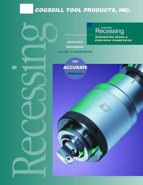
COGSDILL TOOL PRODUCTS, INC.<br />
G R OOV I NG<br />
R ECES S I N G<br />
FACI NG & C H A M FE R I NG<br />
FAS T<br />
AC CUR ATE<br />
REPEATABLE<br />
Automatic<br />
R e c e s s i n g<br />
G E N E R ATI NG H EADS &<br />
PR ECISION C H A M FE R I NG
Recessing<br />
© COPYRIGHT 2007 COGSDILL TOOL PRODUCTS, INC. CATALOG NO. 400 U.S. 5-07<br />
contents<br />
Automatic<br />
Recessing<br />
GENERATING HEADS &<br />
PRECISION CHAMFERING<br />
2<br />
Automatic Recessing Tools<br />
Overview of Automatic Recessing<br />
4 Tool Selection<br />
5 AR Series Operating Principle<br />
7 AR Automatic Recessing Heads<br />
10 ARSP Automatic Recessing Short Pilot Heads<br />
13 ARX Automatic Recessing External Heads<br />
17 Pilots<br />
20 Toolholders, Cutters, and Inserts<br />
22 Set-up and Operation<br />
26 Other Non-Stocked and Special Recessing Solutions<br />
27 Application Examples<br />
30 Nobur ® JA Deep Hole Automatic Recessing Heads<br />
36 Set-up and Operation<br />
38 Application Examples<br />
39 Tube Sheet ProTM Grooving Tool<br />
41 Set-up and Operation<br />
43<br />
Generating Heads<br />
Overview of Generating Heads<br />
44 Operating Principle<br />
46 Features and Options<br />
48 Single-Slide Heads<br />
50 Double-Slide Heads<br />
52 Application Examples<br />
55<br />
Precision Chamfering Tools<br />
Nobur ® JB Automatic Back-Chamfering Tool<br />
56 Operating Principle<br />
59 Application Examples<br />
60 Special Solution for Precision Chamfering<br />
61 Operating Principle<br />
62 Application Data Sheet
2<br />
overview<br />
Automatic<br />
Recessing<br />
Cogsdill offers the widest array of standard tooling and the broadest range<br />
of solutions for precision grooving, recessing, and internal and external<br />
facing and chamfering.<br />
SUPERIOR CRAFTSMANSHIP<br />
All moving parts in our recessing heads are hardened<br />
and precision ground to ensure lasting accuracy and<br />
low maintenance costs. Close tolerances virtually<br />
eliminate “backlash” during retraction, for accurate<br />
size on groove width as well as depth. All sliding<br />
surfaces have large, hardened, load-bearing areas for<br />
long life and durability.<br />
We will design and manufacture a complete<br />
tooling package for your application, including<br />
Automatic Recessing heads, cutters and pilots.<br />
The wide variety of standard recessing heads<br />
described in this catalog are available from<br />
stock to suit most applications and machines.<br />
Special recessing heads can be designed and<br />
manufactured for unusual applications.<br />
GREATER ACCURACY, SHORTER CYCLE TIME, LOWER COST<br />
Cogsdill Automatic Recessing Tools will save you time and money.<br />
Cycle time is reduced from minutes or hours to seconds. The<br />
precision is built into the head so that grooves and recesses can<br />
be machined with exceptional accuracy and repeatability. The<br />
Automatic Recessing head changes the operational direction by<br />
90˚ (i.e., axial spindle motion is converted to radial cutter movement).<br />
Recessing operations can be performed on a variety of machines,<br />
even on a drill press.<br />
SUPERIOR CONSTRUCTION<br />
Compression of the head between the machine spindle and the<br />
workpiece or jig plate actuates a sliding inclined wedge mechanism,<br />
thereby extending the cutter. Groove depth can be machined with<br />
great accuracy.<br />
The cutter retracts radially prior to axial withdrawal of the tool from<br />
the bore, for accurate control of groove width. This design also<br />
results in a constant linear relationship between spindle movement<br />
and cutter movement. The straight-line movement of the cutter<br />
makes cutter regrinding easier.
ARSP Recessing Head<br />
Nobur ®JA-2000 Tool<br />
AR Recessing Head<br />
ARX Recessing Head<br />
Nobur ®JA Tool<br />
Cutaway view of parts machined using Cogsdill Automatic Recessing Tools.<br />
Grooves and recesses are machined with exceptional accuracy and repeatability.<br />
3
4<br />
Automatic Recessing Quick Reference<br />
TOOL SELECTION CHART<br />
Cogsdill Automatic Recessing heads are stocked in four basic categories, including the<br />
AR series and our Nobur ® recessing heads. Head models are available to suit most<br />
applications and machining set-ups. The chart below provides a brief overview<br />
of each head type, and identifies the types of machines to which each head is suited.<br />
HEAD TYPE & DESCRIPTION<br />
NOTE: See photos on previous page<br />
AR Automatic Recessing<br />
Pilots off workpiece or jig plate. Micrometer stop controls depth<br />
of cut. Tool adjustment controls axial location. Through-shank<br />
coolant and overtravel shanks are standard.<br />
ARSP Automatic Recessing — Short Pilot<br />
Short, compact design. For applications with work length<br />
restrictions. Minimal overall length. Pilots off workpiece. Micrometer<br />
stop controls depth of cut. Tool adjustment controls axial location.<br />
Through-tool coolant and overtravel shanks are standard.<br />
ARX Automatic Recessing — External<br />
For external grooving. Pilots off workpiece. Micrometer stop<br />
controls depth of cut. Tool adjustment is controlled within the<br />
fitted tooling. Overtravel shanks are standard.<br />
Nobur ® JA and JA-2000 Deep-Hole Recessing<br />
For deep-bore recessing and grooving. Pilot-supported cutting<br />
action. Micrometer-stop adjustment. Multiple grooves,<br />
chamfers, or metering lands. Back-chamfering and facing of<br />
deep bores.<br />
MACHINE TYPE<br />
DRILL JIG MILLING CNC TOOL TURRET SCREW SPECIAL<br />
PRESS BORE MACHINE MACHINE LATHE LATHE MACHINE PURPOSE
Operating Principle<br />
The AR Series Automatic Recessing Tool is made up of three basic components:<br />
head, cutter, and pilot. The head is usually standard and consists of shank and tool<br />
body. All cutters and pilots are manufactured to suit your application.<br />
AR16 Recessing Head<br />
AR Series<br />
AUTOMATIC RECESSING<br />
5
6<br />
Operating Principle<br />
Illustrated below is the basic operating principle for AR, ARSP and ARX Recessing<br />
Heads. The head type shown below is the AR model.<br />
1 Approach Stroke<br />
The tool is rotating in a machine<br />
spindle. The spindle is lowered,<br />
and the tool moves into position.<br />
2 Feed Stroke<br />
The pilot is located in the bore<br />
against the face of the workpiece.<br />
Downward pressure causes<br />
compression of the recessing<br />
head, thereby actuating the slide<br />
mechanism which feeds the cutter<br />
out radially into the work.<br />
AR Series<br />
AUTOMATIC RECESSING<br />
3 End of Feed Stroke<br />
The correct depth of cut is obtained<br />
when the micrometer stop bottoms<br />
against the front body, making it<br />
impossible to continue the cut.<br />
Groove location is controlled by the<br />
tool adjustment system on the<br />
shank end of the cutter.<br />
When the spindle is retracted, pressure is relieved, and the tool is withdrawn from the bore. The cutter retracts and returns to<br />
its starting position. The piloted bearing absorbs both thrust and rotation. It remains stationary in the bore of the workpiece,<br />
under load, until the cutter is fully retracted, thereby preventing scoring of the workpiece.
AR Recessing Head<br />
General purpose tool for use on:<br />
■ Drill presses<br />
■ Jig boring machines<br />
■ Milling machines<br />
■ CNC machines<br />
■ Tool lathes<br />
■ Turret lathes<br />
■ Horizontal boring machines<br />
■ Screw machines<br />
■ Special purpose machines<br />
Features:<br />
AR16<br />
■ Pilots off workpiece or jig plate<br />
■ Micrometer stop controls depth of cut<br />
■ Tool adjustment controls axial location<br />
■ Through-shank coolant is standard<br />
■ Overtravel shanks are standard<br />
AR Series<br />
AUTOMATIC RECESSING<br />
7
8<br />
Specifications<br />
AR Recessing Head<br />
INCH [METRIC]<br />
.<br />
HEAD<br />
TYPE<br />
AR10<br />
AR16<br />
AR20<br />
.<br />
APPROX. CAPACITY<br />
RANGE *<br />
0.216<br />
[5.5]<br />
0.984<br />
[25.0]<br />
0.590<br />
[15.0]<br />
1.772<br />
[45.0]<br />
0.866<br />
[22.0]<br />
2.362<br />
[60.0]<br />
.<br />
MAXIMUM<br />
CUTTER TRAVEL<br />
0.197<br />
[5.0]<br />
0.276<br />
[7.0]<br />
0.394<br />
[10.0]<br />
.<br />
SHANKS<br />
0.750in/20mm<br />
No 2 MT<br />
SK40/CAT40<br />
BT40<br />
1.000in/25mm<br />
No 3 MT<br />
SK40/CAT40<br />
SK50/CAT50<br />
BT40<br />
BT50<br />
1.500in/40mm<br />
SK40/CAT40<br />
SK50/CAT50<br />
BT40<br />
BT50<br />
.<br />
(A) FREE<br />
LENGTH<br />
4.083<br />
[103.70]<br />
4.894<br />
[124.32]<br />
6.248<br />
[158.70]<br />
5.657<br />
[143.70]<br />
5.547<br />
[140.90]<br />
5.796<br />
[147.23]<br />
7.713<br />
[195.90]<br />
6.299<br />
[160.00]<br />
7.122<br />
[180.90]<br />
8.152<br />
[178.90]<br />
6.591<br />
[167.40]<br />
8.756<br />
[222.40]<br />
7.343<br />
[186.50]<br />
8.165<br />
[207.40]<br />
8.087<br />
[205.40]<br />
.<br />
.<br />
.<br />
.<br />
(B)<br />
(C)<br />
(D) (E) REF MIN<br />
TOOL BODY CUTTER SHANK MASTER PILOT CUTTER LENGTH<br />
ø1.58<br />
[ø40.0]<br />
ø2.56<br />
[ø65.0]<br />
ø3.15<br />
[ø80.0]<br />
ø0.394<br />
[ø10.0]<br />
ø0.630<br />
[ø16.0]<br />
ø0.787<br />
[ø20.0]<br />
ø0.591<br />
[ø15.0]<br />
ø1.416<br />
[ø36.0]<br />
ø1.772<br />
[ø45.0]<br />
AR Series<br />
AUTOMATIC RECESSING<br />
The Feed Ratio is the ratio of<br />
spindle to radial cutter movement<br />
1.48<br />
[37.6]<br />
2.03<br />
[51.5]<br />
2.43<br />
[61.8]<br />
.<br />
(F)<br />
BORE DEPTH<br />
0.85<br />
[21.60]<br />
1.19<br />
[30.23]<br />
1.46<br />
[37.08]<br />
Z.<br />
(G)<br />
OVERTRAVEL<br />
* The capacity range shown is not intended as an absolute limitation. The maximum diameter shown in the chart is defined as<br />
the suggested maximum groove diameter, dependent upon cutting forces, and intended for the sake of comparison only.<br />
0.06<br />
[1.5]<br />
0.06<br />
[1.5]<br />
0.12<br />
[3.0]<br />
.<br />
(H) REF<br />
TO FRONT NUT<br />
0.157<br />
[4.0]<br />
0.187<br />
[4.76]<br />
0.224<br />
[5.70]
Bill of Materials<br />
AR Recessing Head<br />
1 Master Pilot<br />
2 Front Nut<br />
3 Back Plate<br />
4 Chip Guard<br />
5 Front Body<br />
6 Toolslide<br />
7 Rear Body<br />
8 Spring Plate<br />
9 Coolant Pipe<br />
10 Micrometer Nut<br />
12 Over-rider Dowel<br />
13 Slipper<br />
14 Slipper Pin<br />
15 Copper Pad<br />
16 Shank<br />
19 Back Plate Dowel<br />
20 Spring Plate Pipe<br />
21 Centralising Pin<br />
100 Set Screw<br />
101 Double Angular<br />
103 Contact Bearing<br />
103 Spring<br />
104 Spring<br />
106 Tool Clamp Screw<br />
107 Tool Adjust Screw<br />
AR Series<br />
AUTOMATIC RECESSING<br />
108 Oiler<br />
109 Retaining Screw<br />
110 Micrometer Screw<br />
111 Disc Springs<br />
112 Key<br />
113 Torx Screw<br />
114 Ball Bearing<br />
115 Centralising Screw<br />
9
10<br />
ARSP Short-Pilot Head<br />
Short, compact design for use on:<br />
■ CNC machining centers<br />
■ Turret lathes<br />
■ Tool lathes<br />
■ Screw machines<br />
■ Special purpose machines<br />
Features:<br />
■ For applications with work length restrictions<br />
■ Minimal overall length<br />
■ Pilots off workpiece<br />
■ Micrometer stop controls depth of cut<br />
■ Tool adjustment controls axial location<br />
■ Through-tool coolant<br />
■ Overtravel shanks are standard<br />
AR Series<br />
AUTOMATIC RECESSING
Specifications<br />
ARSP Short-Pilot Head<br />
INCH [METRIC]<br />
.<br />
HEAD<br />
TYPE<br />
ARSP1<br />
ARSP2<br />
.<br />
APPROX. CAPACITY<br />
RANGE *<br />
0.216<br />
[5.5]<br />
0.984<br />
[25.0]<br />
0.590<br />
[15.0]<br />
1.772<br />
[45.0]<br />
.<br />
MAXIMUM<br />
CUTTER TRAVEL<br />
0.118<br />
[3.0]<br />
0.197<br />
[5.0]<br />
.<br />
SHANKS<br />
0.750in/20mm<br />
No 2 MT<br />
1.000in/25mm<br />
No 3 MT<br />
.<br />
(A) FREE<br />
LENGTH<br />
2.510<br />
[63.75]<br />
3.322<br />
[84.37]<br />
3.699<br />
[93.95]<br />
3.948<br />
[100.28]<br />
.<br />
(B)<br />
TOOL BODY<br />
ø1.70<br />
[ø43.25]<br />
ø2.36<br />
[ø60.0]<br />
.<br />
(C)<br />
CUTTER SHANK<br />
ø0.394<br />
[ø10.0]<br />
ø0.472<br />
[ø12.0]<br />
.<br />
(D)<br />
MASTER PILOT<br />
ø0.591<br />
[ø15.0]<br />
ø1.091<br />
[ø27.7]<br />
AR Series<br />
AUTOMATIC RECESSING<br />
The Feed Ratio is the ratio of<br />
spindle to radial cutter movement<br />
.<br />
(E) REF MIN<br />
CUTTER LENGTH<br />
1.09<br />
[27.6]<br />
1.44<br />
[36.5]<br />
.<br />
(F)<br />
BORE DEPTH<br />
0.63<br />
[16.0]<br />
0.81<br />
[20.5]<br />
.<br />
(G)<br />
OVERTRAVEL<br />
* The capacity range shown is not intended as an absolute limitation. The maximum diameter shown in the chart is defined as<br />
the suggested maximum groove diameter, dependent upon cutting forces, and intended for the sake of comparison only.<br />
0.06<br />
[1.5]<br />
0.06<br />
[1.5]<br />
.<br />
(H) REF<br />
TO FRONT NUT<br />
0.160<br />
[4.05]<br />
0.158<br />
[4.00]<br />
11
12<br />
Bill of Materials<br />
ARSP Short-Pilot Head<br />
1 Master Pilot<br />
2 Front Shell<br />
3 Back Plate<br />
5 Front Body<br />
6 Toolslide<br />
7 Rear Body<br />
10 Micrometer Nut<br />
12 Over-rider Dowel<br />
13 Slipper<br />
14 Slipper Pin<br />
15 Copper Pad<br />
16 Shank<br />
19 Back Plate Dowel<br />
100 Set Screw<br />
101 Double Angular<br />
103 Contact Bearing<br />
104 Spring<br />
105 Head Screw<br />
103 Screw<br />
106 Tool Clamp Screw<br />
AR Series<br />
AUTOMATIC RECESSING<br />
107 Tool Adjust Screw<br />
110 Micrometer Screw<br />
111 Disc Springs<br />
112 Key
ARX External Head<br />
External grooving tool for use on:<br />
■ Drill presses<br />
■ Milling machines<br />
■ CNC machines<br />
■ Turret lathes<br />
■ Screw machines<br />
■ Special purpose machines<br />
Features:<br />
■ Pilots off workpiece<br />
■ Micrometer stop controls depth of cut<br />
■ Tool adjustment is controlled within the fitted tooling<br />
■ Overtravel shanks are standard<br />
AR Series<br />
AUTOMATIC RECESSING<br />
■ Optional balance block available with two-slot chip<br />
guard for high-speed applications<br />
13
14<br />
ARX Tooling Components AR Series<br />
ARX toolholder, cartridge, and insert are shown below.<br />
Replaceable carbide inserts are used where applications permit.<br />
ARX toolholders, insert cartridges, and carbide inserts are made to order from standard blanks. Part pilots are designed<br />
and manufactured to suit the application; the master pilot is part of the recessing head.<br />
AUTOMATIC RECESSING<br />
Drawing depicts adjustment of groove location, as<br />
measured from the end of the part.
Specifications<br />
ARX External Head<br />
INCH [METRIC]<br />
.<br />
HEAD<br />
TYPE<br />
ARX10<br />
ARX16<br />
ARX20<br />
.<br />
.<br />
.<br />
CAPACITY RANGE<br />
PART GROOVE *<br />
DIAMETER LOCATION<br />
0.157–0.787<br />
[4.0–20.0]<br />
0.630–1.654<br />
[16.0–42.0]<br />
0.866–2.992<br />
[22.0–76.0]<br />
UP TO<br />
1.250 [31.75]<br />
UP TO<br />
1.375 [34.93]<br />
UP TO<br />
1.500 [38.10]<br />
.<br />
MAXIMUM<br />
CUTTER<br />
TRAVEL<br />
0.197<br />
[5.0]<br />
0.276<br />
[7.0]<br />
0.394<br />
[10.0]<br />
.<br />
SHANKS<br />
0.750in/20mm<br />
No 2 MT<br />
SK40/CAT40<br />
BT40<br />
1.000in/25mm<br />
No 3 MT<br />
SK40/CAT40<br />
SK50/CAT50<br />
BT40<br />
BT50<br />
1.500in/40mm<br />
SK40/CAT40<br />
SK50/CAT50<br />
BT40<br />
BT50<br />
.<br />
(A) FREE<br />
LENGTH<br />
4.083<br />
[103.70]<br />
4.894<br />
[124.32]<br />
6.248<br />
[158.70]<br />
5.657<br />
[143.70]<br />
5.547<br />
[140.90]<br />
5.796<br />
[147.23]<br />
7.713<br />
[195.90]<br />
6.299<br />
[160.00]<br />
7.122<br />
[180.90]<br />
8.152<br />
[178.90]<br />
6.591<br />
[167.40]<br />
8.756<br />
[222.40]<br />
7.343<br />
[186.50]<br />
8.165<br />
[207.40]<br />
8.087<br />
[205.40]<br />
.<br />
(B)<br />
TOOL<br />
BODY<br />
ø1.58<br />
[ø40.0]<br />
ø2.56<br />
[ø65.0]<br />
ø3.15<br />
[ø80.0]<br />
.<br />
(C)<br />
CUTTER<br />
SHANK<br />
0.625<br />
[15.88]<br />
1.000<br />
[25.40]<br />
1.250<br />
[31.75]<br />
.<br />
(D)<br />
MASTER<br />
PILOT<br />
ø0.591<br />
[ø15.0]<br />
ø1.416<br />
[ø36.0]<br />
ø1.772<br />
[ø45.0]<br />
AR Series<br />
AUTOMATIC RECESSING<br />
The Feed Ratio is the ratio of<br />
spindle to radial cutter movement<br />
.<br />
(E) REF MIN<br />
CUTTER<br />
LENGTH<br />
1.48<br />
[37.6]<br />
2.03<br />
[51.5]<br />
2.43<br />
[61.8]<br />
.<br />
(F)<br />
BORE<br />
DEPTH<br />
0.85<br />
[21.60]<br />
1.19<br />
[30.23]<br />
1.46<br />
[37.08]<br />
.<br />
(G)<br />
OVER<br />
TRAVEL<br />
0.06<br />
[1.5]<br />
0.06<br />
[1.5]<br />
0.12<br />
[3.0]<br />
.<br />
(H)<br />
MOUNTING<br />
0.636<br />
[16.16]<br />
1.048<br />
[26.63]<br />
1.294<br />
[32.87]<br />
* The capacity range shown is not intended as an absolute limitation. It defines the normal range when using standard<br />
components. The diameter range represents the approximate part diameter. The groove location is the approximate distance to<br />
the groove measured from the end of the part.<br />
.<br />
(J) REF<br />
TO FRONT<br />
NUT<br />
0.157<br />
[4.0]<br />
0.187<br />
[4.76]<br />
0.224<br />
[5.70]<br />
15
16<br />
Bill of Materials AR Series<br />
ARX External Head<br />
1 Master Pilot<br />
2 Front Nut<br />
3 Back Plate<br />
4 Standard Chip Guard<br />
4A Two Slot Chip Guard<br />
5 Front Body<br />
6 Toolslide<br />
7 Rear Body<br />
8 Spring Plate<br />
9 Coolant Pipe<br />
10 Micrometer Nut<br />
12 Over-rider Dowel<br />
13 Slipper<br />
14 Slipper Pin<br />
15 Copper Pad<br />
16 Shank<br />
19 Back Plate Dowel<br />
20 Spring Plate Pipe<br />
21 Centralising Pin<br />
100 Set Screw<br />
101 Double Angular<br />
103 Contact Bearing<br />
104 Spring<br />
108 Oiler<br />
109 Retaining Screw<br />
AUTOMATIC RECESSING<br />
110 Micrometer Screw<br />
111 Disc Springs<br />
112 Key<br />
113 Torx Screw<br />
115 Centralizing Screw
Pilots AR Series<br />
Pilots are required to locate and stabilize the recessing head in the component bore. All<br />
pilots are manufactured to suit the application. Although the basic design and<br />
dimensions are standardized as shown on page 18, the locating diameter of the pilot is<br />
designed specifically for your component. Part pilots are retained in the master pilot by<br />
three retaining screws.<br />
AUTOMATIC RECESSING<br />
17
18<br />
Specifications PILOTS<br />
MASTER PILOT PART PILOT<br />
INCH [METRIC] .<br />
.<br />
HEAD<br />
PILOTS<br />
ARSP-1<br />
ARSP-2<br />
AR10<br />
ARX10<br />
AR16<br />
ARX16<br />
AR20<br />
ARX20<br />
(ØA)<br />
-.0003 [-0.008]<br />
.5904<br />
[14.995]<br />
1.0896<br />
[27.675]<br />
.5904<br />
[14.995]<br />
1.415<br />
[35.95]<br />
1.772<br />
[44.99]<br />
.<br />
(B)<br />
.394<br />
[10.00]<br />
.551<br />
[14.00]<br />
.500<br />
[12.70]<br />
.551<br />
[14.00]<br />
.748<br />
[19.00]<br />
.<br />
(ØC)<br />
MAX<br />
.472<br />
[12.00]<br />
.969<br />
[24.60]<br />
.472<br />
[12.00]<br />
1.295<br />
[32.90]<br />
1.63<br />
[41.4]<br />
ALL UNSPECIFIED DIMENSIONAL TOLERANCES ARE ±0.005 [0.13]<br />
.<br />
(D)<br />
-.005 [-0.13]<br />
.098<br />
[2.50]<br />
.098<br />
[2.50]<br />
.100<br />
[2.55]<br />
.130<br />
[3.30]<br />
.148<br />
[3.75]<br />
.<br />
(ØE)<br />
-.005 [-0.13]<br />
.909<br />
[23.10]<br />
1.409<br />
[35.80]<br />
.844<br />
[21.45]<br />
1.811<br />
[46.00]<br />
2.299<br />
[58.40]<br />
AR Series<br />
AUTOMATIC RECESSING<br />
Note: If machine lacks internal coolant<br />
capability, part pilot must be designed<br />
with coolant windows<br />
.<br />
(F)<br />
.394<br />
[1.00]<br />
.394<br />
[1.00]<br />
.394<br />
[1.00]<br />
.394<br />
[1.00]<br />
.394<br />
[1.00]<br />
.<br />
(G)<br />
.138<br />
[3.50]<br />
.138<br />
[3.50]<br />
.138<br />
[3.50]<br />
.138<br />
[3.50]<br />
.177<br />
[4.50]<br />
.<br />
(H)<br />
120˚<br />
120˚<br />
120˚<br />
120˚<br />
120˚
Piloting Methods AR Series<br />
AUTOMATIC RECESSING<br />
Pilots on I.D. and stops on face of component. Pilots on O.D. and stops on face of component.<br />
Pilots and stops on fixture plate. Pilots on fixture plate and stops on face of<br />
19
20<br />
Toolholders, Cutters, Inserts AR Series<br />
AUTOMATIC RECESSING<br />
Toolholders are designed to suit the application. The basic design of the toolholder is standardized (see page 21), but the<br />
diameter and length of the holder is designed to suit your component.<br />
Toolholders with replaceable inserts are used where application parameters permit. As a general rule, toolholders for holes<br />
9/16 inch (approx. 14.5mm) and larger utilize replaceable inserts. Cutters for smaller diameters are usually of brazedcarbide<br />
or high-speed steel construction.<br />
Our improved toolholder design allows fast and easy incremental adjustment of axial groove location without removing the<br />
toolholder from the head.<br />
Many inserts can be manufactured from standard blanks (see bottom of page 21.) Toolholders and inserts can be designed<br />
for back-chamfers, thread reliefs, multiple grooves, and special groove geometries; submit a part print and request a<br />
quotation. Toolholders can be designed with an internal coolant port where required<br />
(see example below).<br />
Our improved toolholder design allows fast and easy incremental<br />
adjustment of axial groove location without removing the<br />
toolholder from the head.<br />
(See set-up and operation guide on page 22 for more information)
Specifications AR Series<br />
METRIC [INCH]<br />
.<br />
HEAD<br />
TYPE<br />
ARSP–1<br />
ARSP–2<br />
AR10<br />
AR16<br />
AR20<br />
.<br />
(A)<br />
10.00<br />
[0.394]<br />
12.00<br />
[0.472]<br />
10.00<br />
[0.394]<br />
16.00<br />
[0.630]<br />
20.00<br />
[0.787]<br />
.<br />
(B)<br />
12.70<br />
[0.500]<br />
17.25<br />
[0.679]<br />
20.80<br />
[0.819]<br />
29.50<br />
[1.161]<br />
36.30<br />
[1.429]<br />
.<br />
(C)<br />
0.50<br />
[0.020]<br />
0.50<br />
[0.020]<br />
0.50<br />
[0.020]<br />
0.50<br />
[0.020]<br />
0.50<br />
[0.020]<br />
.<br />
(D)<br />
9.00<br />
[0.354]<br />
12.50<br />
[0.492]<br />
15.25<br />
[0.600]<br />
19.50<br />
[0.768]<br />
25.40<br />
[1.000]<br />
AR Series Replaceable Inserts<br />
TOOLHOLDER<br />
.<br />
(E)<br />
1.50<br />
[0.059]<br />
3.00<br />
[0.118]<br />
1.50<br />
[0.059]<br />
3.00<br />
[0.118]<br />
5.00<br />
[0.197]<br />
.<br />
(F)<br />
3.00<br />
[0.118]<br />
5.00<br />
[0.197]<br />
3.00<br />
[0.118]<br />
5.00<br />
[0.197]<br />
6.00<br />
[0.236]<br />
.<br />
(G)<br />
h11<br />
0.70<br />
[0.028]<br />
1.60<br />
[0.063]<br />
0.80<br />
[0.031]<br />
1.60<br />
[0.063]<br />
1.75<br />
[0.069]<br />
.<br />
(H)<br />
2.30<br />
[0.091]<br />
3.40<br />
[0.134]<br />
2.20<br />
[0.087]<br />
3.40<br />
[0.134]<br />
4.25<br />
[0.167]<br />
.<br />
(J)<br />
3.35<br />
[0.132]<br />
5.75<br />
[0.226]<br />
6.70<br />
[0.264]<br />
6.10<br />
[0.240]<br />
10.00<br />
[0.394]<br />
.<br />
(K)<br />
8.00<br />
[0.315]<br />
9.50<br />
[0.374]<br />
7.75<br />
[0.305]<br />
12.50<br />
[0.492]<br />
15.50<br />
[0.610]<br />
.<br />
ø(M)<br />
3.00<br />
[0.118]<br />
3.00<br />
[0.118]<br />
3.00<br />
[0.118]<br />
4.00<br />
[0.157]<br />
5.00<br />
[0.197]<br />
.<br />
(N)<br />
max<br />
0.50<br />
[0.020]<br />
0.50<br />
[0.020]<br />
0.50<br />
[0.020]<br />
0.50<br />
[0.020]<br />
0.50<br />
[0.020]<br />
.<br />
(P)<br />
9.50<br />
[0.374]<br />
15.50<br />
[0.610]<br />
19.00<br />
[0.748]<br />
26.50<br />
[1.043]<br />
33.30<br />
[1.311]<br />
Standard insert blanks Replaceable carbide inserts are used where applications permit.<br />
Special or intricate geometries are available.<br />
AUTOMATIC RECESSING<br />
.<br />
(R)<br />
0.70<br />
[0.028]<br />
0.80<br />
[0.031]<br />
0.70<br />
[0.028]<br />
0.80<br />
[0.031]<br />
1.00<br />
[0.039]<br />
21
22<br />
Set-up AR Series<br />
There are four basic steps to the set-up of AR Series Automatic Recessing heads.<br />
(Set-up procedures differ somewhat for internal and external heads.)<br />
1 Install pilot<br />
For all head types, the pilot must be installed in the head.<br />
The pilot will fit either directly into the sealed bearing or into a<br />
master pilot for quick and easy tool changes.<br />
2 Install cutter/toolholder<br />
The cutter normally comes in three different styles:<br />
■ High-speed steel cutter<br />
■ Tungsten carbide brazed-tip cutters<br />
■ Replaceable-insert toolholders<br />
For internal recessing heads, install the cutter in the<br />
head with the cutting edge pointing in the direction of cut<br />
(i.e., in the direction of toolslide movement). The cutter is<br />
clamped and fixed in position by two set screws in the<br />
head. The cutter must be positioned radially in the head so<br />
that the cutting edge will be on center as the tool moves<br />
out to cut. This is facilitated by the use of a key in the<br />
cutter shank, which automatically aligns the cutting edge<br />
on center.<br />
For external recessing heads, install the toolblock onto<br />
the toolslide and secure in place with two caphead screws.<br />
An adjustable cartridge is fitted to the toolblock and held in<br />
place by a buttonhead screw. An inexpensive, replaceable<br />
insert is fitted to this cartridge and secured in place by an<br />
insert screw. The cutting edge of the insert is automatically<br />
aligned on center as the toolblock is secured to the head.<br />
AUTOMATIC RECESSING<br />
3 Set cutter projection from pilot<br />
For all head types, the projection of the cutter from the pilot<br />
must be set properly in order to achieve accurate groove<br />
location.<br />
For internal recessing heads, groove location is controlled<br />
by the tool adjustment set screw, which is located in the<br />
toolslide. The tool adjustment screw is accessed through a<br />
hole in the chip guard on the front shell. Insert the toolholder<br />
until it bottoms out in the toolslide. Tighten tool adjustment<br />
screw and move cutter out until the set dimension (between<br />
cutter and pilot) is achieved. Then lock the cutter in place by<br />
tightening the locking set screws.<br />
For external recessing heads, groove location is controlled<br />
by a set screw in the end of the adjustable cartridge that is<br />
mounted on the toolblock. Once the groove location is set,<br />
lock the cartridge in place with the buttonhead locking screw.
Set-up AR Series<br />
(continued)<br />
4 Depth of cut/tool travel<br />
For all head types, depth of cut is controlled by a<br />
micrometer nut that allows the head to pre-set off the<br />
machine. The standard tool feed ratio for all heads is 2:1<br />
(i.e., the ratio of spindle to radial cutter movement).<br />
Refer to the drawing supplied with the tool for the set-up<br />
dimension. If the drawing is unavailable, follow this<br />
procedure: Add the depth of cut (the distance from the I.D.<br />
of the bore to the bottom of the groove) to the clearance<br />
between the cutter and the I.D of the bore. Multiply this<br />
figure by the feed ratio (i.e., multiply by 2 for standard feed<br />
ratio) in order to arrive at the distance to set the micrometer<br />
nut from the front body. This distance should be set using<br />
gauge blocks or by fine-tuning the micrometer nut position<br />
manually to achieve the desired groove depth.<br />
.<br />
HEAD<br />
TYPE<br />
AR10<br />
AR16<br />
AR20<br />
ARSP-1<br />
ARSP-2<br />
AUTOMATIC RECESSING<br />
.<br />
HEX WRENCHES REQUIRED FOR ADJUSTING AR HEADS<br />
.<br />
MICROMETER<br />
NUT SCREW<br />
1.5mm<br />
3.0mm<br />
4.0mm<br />
1.5mm<br />
2.5mm<br />
.<br />
INSERT TOOL<br />
HOLDER<br />
(LENGTH ADJ.)<br />
2.0mm<br />
3.0mm<br />
4.0mm<br />
1.5mm<br />
2.5mm<br />
Approximate adjustment gap for all internal<br />
recessing heads, when tool is in set position.<br />
.<br />
MASTER<br />
PILOT<br />
1.5mm<br />
1.5mm<br />
2.0mm<br />
1.5mm<br />
1.5mm<br />
23
24<br />
Operation AR Series<br />
Speeds & Feeds<br />
Please refer to the charts below for speed and feed recommendations for specific<br />
material types. The charts are intended as a guide or starting point; the actual speed<br />
and feed used will depend on a number of factors, including type of machine, condition<br />
of machine spindle, rigidity of fixturing, type of coolant used or dry cutting, tool length,<br />
cutter geometry, interrupted cut, etc.<br />
AUTOMATIC RECESSING<br />
INCH<br />
.<br />
.<br />
.<br />
.<br />
.<br />
.<br />
.<br />
.<br />
.<br />
.<br />
MATERIAL<br />
CUTTING SPEED (FT/MIN) FEED RATE (INCHES/REV)<br />
TOP RAKE (DEGREES)<br />
HSS Carbide HSS Carbide HSS Carbide<br />
Aluminum 200—300 400—700 .002—.005 .002—.005 10—15 8—12<br />
Brass 100—200 200—525 .002—.005 .002—.005 0—3 0—3<br />
Bronze 50—130 100—400 .002—.005 .002—.005 3—5 3—5<br />
Cast Iron 50—90 100—180 .002—.004 .002—.005 0—3 0—3<br />
Copper 100—200 200—400 .002—.004 .002—.005 10—15 8—12<br />
Magnesium 200—300 400—700 .004—.006 .004—.006 10—15 8—12<br />
Malleable Cast Iron 50—90 100—200 .002—.004 .003—.005 0—3 0—3<br />
Resin (Plastic) 70—135 160—400 .004—.006 .004—.006 10—15 8—12<br />
Free Cutting Steel 70—100 100—230 .002—.004 .003—.005 5—10 4—8<br />
Annealed Steel 50—70 100—200 .002—.004 .003—.005 5—8 3—6<br />
Wrought Steel 35—70 85—220 .002—.003 .003—.004 5—8 3—6<br />
Alloy Steel 35—70 85—220 .002—.003 .003—.004 4—6 3—6<br />
Tool Steel 35—50 85—150 .001—.002 .002—.003 4—6 3—6<br />
Monel & Stainless 85—135 150—250 .001—.003 .002—.004 10—20 8—12<br />
METRIC<br />
.<br />
.<br />
.<br />
.<br />
.<br />
.<br />
.<br />
.<br />
.<br />
.<br />
MATERIAL<br />
CUTTING SPEED (M/MIN)<br />
FEED RATE (MM/REV)<br />
TOP RAKE (DEGREES)<br />
HSS Carbide HSS Carbide HSS Carbide<br />
Aluminum 60—90 120—210 0,05—0,13 0,05—0,13 10—15 8—12<br />
Brass 30—60 60—160 0,05—0,13 0,05—0,13 0—3 0—3<br />
Bronze 15—40 30—120 0,05—0,13 0,05—0,13 3—5 3—5<br />
Cast Iron 15—25 30—55 0,05—0,10 0,05—0,13 0—3 0—3<br />
Copper 30—60 60—120 0,05—0,10 0,05—0,13 10—15 8—12<br />
Magnesium 60—90 120—210 0,10—0,15 0,10—0,15 10—15 8—12<br />
Malleable Cast Iron 15—25 30—60 0,05—0,10 0,08—0,13 0—3 0—3<br />
Resin (Plastic) 20—40 50—120 0,10—0,15 0,10—0,15 10—15 8—12<br />
Free Cutting Steel 20—30 30—70 0,05—0,10 0,08—0,13 5—10 4—8<br />
Annealed Steel 15—20 30—60 0,05—0,10 0,08—0,13 5—8 3—6<br />
Wrought Steel 10—20 25—65 0,05—0,08 0,08—0,10 5—8 3—6<br />
Alloy Steel 10—20 25—65 0,05—0,08 0,08—0,10 4—6 3—6<br />
Tool Steel 10—15 25—45 0,03—0,05 0,05—0,08 4—6 3—6<br />
Monel & Stainless 25—40 45—75 0,03—0,08 0,05—0,10 10—20 8—12
Operation AR Series<br />
(continued)<br />
Coolant<br />
Regarding the use of coolant, follow normal machine shop procedures for the cutter<br />
material and the material to be machined.<br />
Lubrication<br />
AUTOMATIC RECESSING<br />
1 We recommend a water resistant grease for use in these heads. Kluber Altemp Q NB50 has been thoroughly tested and<br />
found to perform exceptionally well – it is the only grease we recommend. It should be applied to all moving parts and surfaces<br />
when the head is disassembled for cleaning and maintenance, or if the head will be stored for extended periods. Disassembly and<br />
cleaning should be done periodically.<br />
2 To lubricate the heads during use, apply Kluber Altemp Q NB50 grease through the external oilers or grease fittings on the<br />
head. This should be done on a weekly basis, or more frequently if necessary. Lubrication frequency can vary depending on the<br />
working environment, operational speed, coolant used, and number of cycles. Remember, adequate lubrication is vital to long<br />
head life and trouble-free performance.<br />
3 A high-pressure hand pump lube gun is available from Cogsdill to make routine maintenance easy. (Ref. Part No. CN-D24)<br />
25
26<br />
Other Non-Stocked and<br />
Special Recessing Solutions<br />
ARX-S<br />
ARXJ<br />
AR-S<br />
A variation of the ARX head for use on CNC machining or<br />
turning centers. No micrometer stop for depth control. Depth of<br />
cut is controlled by “Z” axis; axial adjustment is controlled by<br />
tool adjustment.<br />
ARJ<br />
For machining grooves or forms in larger bores or for other<br />
special applications. Rigid support in heavy cuts. Micrometer<br />
stop controls depth of cut. Axial location controlled by<br />
adjustable thrust housing. Through-tool coolant.<br />
AR Series<br />
AUTOMATIC RECESSING<br />
A variation of the AR head for use on CNC machining or<br />
turning centers. No micrometer stop for depth control. Depth<br />
of cut is controlled by “Z” axis; axial adjustment is controlled<br />
by tool adjustment. Through-tool coolant.<br />
Designed to run in a rotating bushing mounted in a jig plate.<br />
Exceptional rigidity, especially at high cutting speeds.<br />
Micrometer stop controls depth of cut. Through-tool coolant.<br />
Inquire about these and other non-stocked and special Recessing tool designs. Submit a<br />
completed Application Data Sheet (see pages 62-63) and request a quotation, or contact<br />
our Customer Service Department for more information.
Applications AR Series<br />
AR10 Internal Recessing Head<br />
performing an I.D. grooving operation; pilots in part<br />
ARSP1 Internal Recessing Head<br />
machining an I.D. groove with a radius on a banjo fitting; pilots in part<br />
AUTOMATIC RECESSING<br />
27
28<br />
Applications AR Series<br />
AR20 Internal Recessing Head<br />
machining a back-spotface with an I.D. chamfer; pilots in part<br />
AR16 Internal Recessing Head<br />
performing an I.D. grooving operation; pilots in fixture plate<br />
AUTOMATIC RECESSING
Applications AR Series<br />
ARX10 External Recessing Head<br />
performing an O.D. grooving operation; pilots on part O.D.<br />
and includes balance weight<br />
ARX16 External Recessing Head<br />
machining a face and a double groove on an O.D.; pilots on part O.D.<br />
AUTOMATIC RECESSING<br />
29
30<br />
Nobur ® JA Recessing Head<br />
For deep bore recessing and grooving.<br />
A tool for use on:<br />
■ Drill presses<br />
■ Jig boring machines<br />
■ Milling machines<br />
■ CNC machines<br />
■ Tool or turret lathes<br />
■ Horizontal boring machines<br />
■ Special purpose machines<br />
Features:<br />
Nobur ® JA Series<br />
AUTOMATIC RECESSING<br />
DEEP HOLE<br />
■ In-bore pilot supports cutter along its entire<br />
length – eliminates tool deflection; ensures<br />
concentricity through rigid cutting action<br />
■ Micrometer-stop adjustment<br />
■ Multiple grooves, chamfers, or metering lands<br />
■ O-ring and retaining ring grooves<br />
■ Relief grooves and tube sheet grooves<br />
■ Back-chamfering and facing of deep bores
Nobur ® JA2000 Recessing Head<br />
For deep bore recessing and grooving.<br />
Designed for heavier cuts than the regular JA.<br />
Innovative internal coolant system directs coolant to<br />
cutting edges for improved chip evacuation, longer tool<br />
life, better tool function, and improved repeatability.<br />
For use on machines with internal coolant capability. *<br />
Features:<br />
■ Same in-bore pilot support and micrometer-stop adjustment as the<br />
regular JA<br />
■ Capable of wider cuts than the regular JA in some applications<br />
■ Extremely durable high-load precision dual bearings for long life<br />
■ Easy disassembly and reassembly for maintenance<br />
■ Overtravel units available upon request<br />
Nobur ® JA Series<br />
AUTOMATIC RECESSING<br />
DEEP HOLE<br />
* JA2000 Recessing Heads can be ordered in a Side-Port model for use on machines that do not have through-spindle<br />
coolant capability. Through-shank coolant is standard; specify side-port coolant if desired.<br />
31
32<br />
Operating Principle<br />
1 Approach Stroke<br />
The Nobur ® JA tool is rotating in<br />
a machine spindle. The spindle is<br />
lowered. The tool approaches entry<br />
into the bore.<br />
2 Feed Stroke<br />
The pilot is located in the bore,<br />
stopping against the face of the<br />
workpiece. Downward travel of the<br />
machine spindle compresses the<br />
tool so that the cutter feeds out<br />
radially into the surface of the<br />
workpiece. The pilot rigidly<br />
supports the cutter along its entire<br />
length to eliminate deflection and<br />
ensure concentricity.<br />
Nobur ® JA Series<br />
AUTOMATIC RECESSING<br />
DEEP HOLE<br />
3 End of Feed Stroke<br />
Radial depth of cut is obtained<br />
when the micrometer-stop nut<br />
bottoms out. Groove location is<br />
controlled by the adjusting stopcollar,<br />
which moves the nosepiece<br />
up or down to position the cutter<br />
arm for accurate groove location.
Specifications<br />
.<br />
HEAD<br />
TYPE<br />
JA<br />
JA2000<br />
.<br />
.<br />
. CAPACITY 1<br />
in mm<br />
0.25<br />
1.85<br />
0.25<br />
1.85<br />
6.300<br />
47.10<br />
6.300<br />
47.10<br />
.<br />
.<br />
(A) .<br />
FREE<br />
in mm<br />
3.82 97.00 2.28 57.90<br />
4.43<br />
112.5<br />
.<br />
3.36<br />
.<br />
(B)<br />
in mm<br />
.<br />
85.40<br />
.<br />
2.06<br />
3.00<br />
.<br />
(C)<br />
in mm<br />
.<br />
52.30<br />
76.20<br />
.<br />
2.24<br />
1.53<br />
.<br />
(D)<br />
MAXIMUM<br />
in mm<br />
.<br />
56.90<br />
38.90<br />
Nobur ® JA Series<br />
AUTOMATIC RECESSING<br />
DEEP HOLE<br />
.<br />
1.24<br />
1.03<br />
The Feed Ratio is the ratio of<br />
spindle to radial cutter movement<br />
.<br />
(D)<br />
MINIMUM<br />
in mm<br />
.<br />
31.50<br />
26.20<br />
.<br />
.<br />
(E)<br />
SHANKS 2<br />
3/4” straight 3<br />
1”–12 acme<br />
1-1/16”–12 acme<br />
#2 morse taper<br />
#3 morse taper<br />
1” straight 4<br />
.<br />
3.25<br />
3.63<br />
3.63<br />
3.19<br />
3.88<br />
3.00<br />
.<br />
(F)<br />
in mm<br />
1 Capacity means the suggested maximum groove diameter. Dependent upon cutting forces and bore diameter. Stated capacity is for steel.<br />
2 Shank is included with head. Shanks other than shown can be supplied upon request.<br />
3 Supplied with through-tool coolant.<br />
4 Through-shank coolant is standard; specify side-port coolant if desired.<br />
.<br />
82.60<br />
92.20<br />
92.20<br />
81.00<br />
98.60<br />
76.20<br />
33
34<br />
Bill of Materials Nobur ® JA Series<br />
Nobur ® JA Recessing Head<br />
1 Body Holder<br />
2 Adjustment Nut<br />
2 Assembly<br />
3 Snap Ring<br />
4 Housing-Bearing<br />
4 Stop Collar<br />
5 Bearing Assembly<br />
6 Collar Hub Mounting<br />
7 Leaf Spring (Quantity 3)<br />
8 Screw<br />
8 Locking-Housing<br />
9 Stop<br />
9 Collar-Adjustment<br />
10 Retainer Ring-Insert<br />
11 Lock Screw<br />
12 Retainer Loop<br />
AUTOMATIC RECESSING<br />
DEEP HOLE<br />
13 Pin<br />
14 Spacer/Bushing/<br />
14 Spring<br />
15 Compression<br />
15 Spring Return
Bill of Materials Nobur ® JA Series<br />
Nobur ® JA2000 Recessing Head<br />
NOTE: Coolant location can be changed in the field; consult Sales Department.<br />
1 Spindle<br />
2 O-Ring<br />
3 Compression Spring<br />
4 Spacer Bushing<br />
5 Pin<br />
6 Drive Pin<br />
7 Flat Point Set Screw<br />
8 Stop Nut<br />
9 Socket Head Cap Screw<br />
10 Bearing Sleeve<br />
11 Ball Bearing<br />
12 Outer Bearing Spacer<br />
13 Inner Bearing Spacer<br />
14 Bearing Collar<br />
15 Cone Point Screw<br />
16 Leaf Spring<br />
17 Coolant Tube<br />
18 Housing<br />
19 Flat Point Set Screw<br />
20 Bearing Retainer<br />
21 Stop Collar<br />
AUTOMATIC RECESSING<br />
DEEP HOLE<br />
22 Retaining Ring<br />
Details 23 thru 27 optional<br />
23 Outer Bearing Spacer<br />
24 Inner Bearing Spacer<br />
25 O-Ring<br />
26 Coolant Nipple<br />
27 Pipe Plug (not shown)<br />
35
36<br />
Set-up Nobur ® JA Series<br />
Cogsdill Nobur ® JA tools are easily set. Since the precision feed motion is built into the head, only two adjustments are<br />
required in order to properly set up a tool for operation. Occasionally, compensating adjustments might be required if there is an<br />
error in the initial settings, or to compensate for cutter wear. However, by following the steps prescribed below, it will be easy to<br />
attain the initial set-up.<br />
1 Set front stop collar<br />
This setting determines the position of the groove(s)<br />
relative to the face of the part, or other surface from which<br />
the tool actuates. Simply adjust the threaded stop collar,<br />
measuring from the face of the collar to the top corner of<br />
the cutter until the correct distance is established (refer to<br />
photo A). Once set, the locking screw on the outer tool<br />
body should be tightened.<br />
2 Set the groove diameter to be cut<br />
On manually fed machines, this setting is established by<br />
adjusting the threaded diameter stop nut at the rear of the<br />
tool body. Because the cutter motion is radial, the groove<br />
cut diameter can be measured by using a micrometer to<br />
measure directly across the pilot and cutting edge when<br />
the head is compressed (refer to photo B). Since the pilot<br />
is .002 in. (0.05mm) under the smallest bore diameter, the<br />
cutter should project from the pilot for a distance equal to<br />
the required depth of cut. An alternative setting method is<br />
to measure the projection of the cutter using a surface<br />
plate indicator relative to the centerline of the bore.<br />
Setting the groove diameter for machines with power feed<br />
requires that the diameter stop nut be backed away<br />
(toward the rear of the tool) so that it becomes nonoperative.<br />
Tools with Acme-threaded shanks do not have<br />
the diameter stop nut. The automatic feed on the machine<br />
is then set to produce the cutter projection required to cut<br />
the desired groove diameter. Preset holders and gauges<br />
may also be used to establish the spindle travel limits.<br />
A<br />
AUTOMATIC RECESSING<br />
DEEP HOLE<br />
Since cutter deflection is eliminated due to the support of<br />
the cutter by the arm and pilot, no compensation is<br />
required. Once the above settings are verified, the tool is<br />
ready to use. However, please remember that variations in<br />
bore diameter can cause groove dimensions to vary. A<br />
variation of .001 in. (0.02mm) in bore diameter can result<br />
in a .002 in. (0.05mm) variation in groove diameter.<br />
Therefore, bore tolerances must be limited to less than 1/2<br />
of the tolerance required for the groove diameter. If this<br />
tolerance requirement presents a problem, it might be<br />
necessary to pilot the tool in a fixture instead of piloting in<br />
the bore. The diagram on page 37 shows how to measure<br />
a tool to cut a specific diameter.<br />
B
Set-up and Operation Nobur ® JA Series<br />
(continued)<br />
Diameter Setting Methods<br />
Tool Operation<br />
Cogsdill Nobur ® JA Recessing tools operate automatically as<br />
axial spindle travel is converted into radial cutter travel within<br />
the head. The pilot enters the bore and the stop collar contacts<br />
the front of the part. Continued spindle travel results in<br />
corresponding cutter travel which is rigidly supported within the<br />
part for extreme accuracy. A sealed bearing between the tool<br />
body and the stop collar prevents marking of the workpiece.<br />
Radial cutter advancement is approximately 1/2 of spindle<br />
travel. Depth of cut is precisely controlled by an adjustable<br />
diameter stop nut located on the back end of the tool. A feed<br />
rate of .003–.005 IPR (0.08–0.13mm) is generally used.<br />
Upon completion of the cut, tool withdrawal feed should be at<br />
the cutting feed rate until the stop collar no longer contacts the<br />
part. This will ensure that the cutter has fully retracted into the<br />
pilot before the tool is withdrawn from the part.<br />
Tool Lubrication<br />
AUTOMATIC RECESSING<br />
DEEP HOLE<br />
In order to measure for a specific groove cut diameter, the tool must be actuated to the limit setting by compressing the<br />
actuating assembly against the diameter stop nut. The nominal clearance between the pilot diameter and the minimum bore<br />
diameter is .002” (.05mm).<br />
In applications where water soluble or synthetic coolants<br />
are used, we recommend that, when the machine and tool<br />
are idle, the tool be removed from the spindle and immersed<br />
in oil to keep it lubricated and to prevent rusting of the<br />
internal mechanism.<br />
37
38<br />
Applications<br />
Nobur ® JA Recessing Head<br />
machining eight metering lands in one pass<br />
Nobur ® JA Recessing Head<br />
performing grooving operation with piloting area in advance of cut<br />
PART LAYOUT<br />
Nobur ® JA Recessing Head<br />
back-cutting five locations<br />
Nobur ® JA Series<br />
AUTOMATIC RECESSING<br />
DEEP HOLE<br />
CUT LOCATIONS
overview<br />
Tube Sheet ProTM<br />
For grooving tube sheets in heat exchangers, condensers,<br />
and boilers with maximum productivity and professional<br />
results. Available from stock for four standard tube diameters:<br />
5/8, 3/4, 7/8, and 1 inch. Designed for industry-standard<br />
double-groove configuration.<br />
■ High-quality tool with<br />
a proven design for<br />
grooving tube sheets of<br />
all standard materials.<br />
■ Smooth operation for<br />
accurate groove size<br />
and location, with<br />
good finishes.<br />
■ Easy to adjust for<br />
accuracy from the very<br />
first cut. Set-up<br />
instructions are marked<br />
on tool body for handy<br />
reference–no<br />
measurements<br />
are required.<br />
■ Easy cutter<br />
replacement–no<br />
disassembly required.<br />
■ Short tool stroke, with no<br />
exposed mechanism–no<br />
chip packing or “sticking.”<br />
■ TiN-coated high-speed<br />
steel cutters for long life.<br />
■ Pilots, specifically<br />
designed to maximize<br />
coolant flow for<br />
enhanced tool life, are<br />
interchangeable for<br />
easy diameter changes.<br />
■ Optional overtravel units<br />
available for use on CNC<br />
machines or other<br />
automated machinery, or<br />
when tube sheet is<br />
warped.<br />
Interchangeable pilots allow easy diameter<br />
changes. Pilots are specifically designed to<br />
maximize coolant flow for enhanced tool life.<br />
Grooving Tool<br />
INDUSTRY-<br />
STANDARD<br />
DOUBLE-GROOVE<br />
CONFIGURATION<br />
High-speed steel cutters are<br />
TiN-coated for long life.<br />
39
40<br />
Specifications<br />
■ COMPLETE TOOL ASSEMBLY<br />
Part number Description<br />
■ TSP-00625 5/8 in. complete tool with 3/4 in. SS<br />
■ TSP-00750 3/4 in. complete tool with 3/4 in. SS<br />
■ TSP-00875 7/8 in. complete tool with 3/4 in. SS<br />
■ TSP-01000 1 in. complete tool with 3/4 in. SS<br />
■ TSP-00625-3MT 5/8 in. complete tool with #3MT<br />
■ TSP- 00750-3MT 3/4 in. complete tool with #3MT<br />
■ TSP-00875-3MT 7/8 in. complete tool with #3MT<br />
■ TSP-01000-3MT 1 in. complete tool with #3MT<br />
Note: Pilots made to fit TEMA standard tube sheet hole diameters.<br />
(See under “Pilot Only,” below.)<br />
Overtravel and morse taper shanks are available. (See below.)<br />
■ TSP-00625-1OT 5/8 in. complete tool with 1 in. SS with OT*<br />
■ TSP-00750-1OT 3/4 in. complete tool with 1 in. SS with OT*<br />
■ TSP-00875-1OT 7/8 in. complete tool with 1 in. SS with OT*<br />
■ TSP-01000-1OT 1 in. complete tool with 1 in. SS with OT*<br />
■ HEAD ASSEMBLY ONLY<br />
Part number Description<br />
■ TSPH-3/4SS Tube Sheet Pro head with 3/4 in. SS<br />
■ TSPH-3MT Tube Sheet Pro head with #3MT<br />
■ TSPH-1OT Tube Sheet Pro head with 1 in. SS with OT*<br />
*OVERTRAVEL<br />
■ ARM ONLY<br />
Part number Description<br />
Tube Sheet Pro TM<br />
GROOVING TOOL<br />
■ TSP-02 Small arm (5/8-3/4 in.)<br />
■ TSP-03 Large arm (7/8 –1 in.)<br />
■ PILOT ONLY<br />
Part number Nominal Size (in.) Actual Pilot Dia. (in.)<br />
■ TSP-04 5/8 in. pilot .629<br />
■ TSP-05 3/4 in. pilot .754<br />
■ TSP-06 7/8 in. pilot .879<br />
■ TSP-07 1 in. pilot 1.006<br />
■ CUTTER ONLY<br />
Part number Description<br />
■ TTSP-08 Standard cutter<br />
2 x 1/8 in. grooves<br />
(1/4 in. spacing)<br />
■ TSP-08A Optional cutter<br />
2 x 1/8 in. grooves<br />
(3/8 in. spacing)
Set-up Tube Sheet Pro TM<br />
Refer to details drawing on next page.<br />
■ MAKE SURE<br />
■ The cutter (Detail #8) is mounted in the arm (D #2 or #3) with two (2) #4-40 x 0.25” Torx screws (D #9).<br />
■ The pilot (D #4, #5, #6, or #7) and arm are installed at the same time.<br />
GROOVING TOOL<br />
■ The pull yoke end of the arm (opposite the cutter end of the arm) is installed on the dowel (pull) pin (D<br />
#34) in the recessing head. The arm should be installed with the elevated platform contacting the leaf<br />
springs (D #24) in the head.<br />
■ Insert the pilot into the head, making sure the arm is mounted in the slot in the pilot. The pilot must be<br />
centered in the head and flush with the mounting face. The pilot is held into place with three (3) #10-24 x<br />
5/8” cap screws (D #38).<br />
■ DEPTH TO CUT (groove location)<br />
■ The stop (D #25) and housing (D #23) move together to adjust the tool to the desired depth to cut. This<br />
adjustment is made by loosening the locking screw (D #30) and screwing the housing/stop in or out. Do not<br />
force the housing; it should turn freely when the locking screw is backed off. Secure the position of the<br />
housing and the stop with the locking screw. The stop should rotate freely at all times.<br />
■ DEPTH OF CUT (groove diameter)<br />
■ The depth of cut is controlled and adjusted by the adjusting collar (D #21). The adjusting collar is marked<br />
with details for setting the tool for standard tube sheet grooves. The adjusting collar is also marked so it can<br />
be adjusted in 0.001” increments. The locking screw must be loosened to adjust the adjusting collar. When<br />
the desired depth of cut is achieved, tighten the locking screw on the adjusting collar. If the machine holding<br />
the tool is controlling the depth of cut, back the adjusting collar off and secure it so it will not stop or restrict<br />
the tool. The adjusting collar must remain on the tool in order for the tool to operate correctly.<br />
The adjusting<br />
collar is marked<br />
with details for<br />
setting the tool for<br />
standard tube<br />
sheet grooves.<br />
The adjusting<br />
collar is also<br />
marked so it can<br />
be adjusted in<br />
0.001” increments.<br />
41
42<br />
Operation Tube Sheet Pro TM<br />
GROOVING TOOL<br />
■ MAKE SURE<br />
■ The tool must be centered over the hole to be grooved.<br />
■ Refer below for speeds and feeds.<br />
■ Coolant is strongly recommended for longer cutter life.<br />
■ With the tool rotating, feed the tool down until the pilot is in the hole and the nosepiece has come into contact with the<br />
surface of the part.<br />
■ At this time the cutter will begin to actuate.<br />
■ Feed the tool in until the cut is complete (the adjusting collar bottoms out).<br />
■ Feed the tool out at the same rate.<br />
■ CUTTER CHANGE<br />
■ The cutter can be replaced in the tool without removal from the machine or disassembly. Remove the two (2) #4-40 x 0.25<br />
Torx screws holding the cutter in place. Flush the cutter pocket in the arm to remove any chips or foreign material.<br />
Replace the cutter and secure with two (2) #4-40 x 0.25 Torx screws.<br />
■ PILOT CHANGE<br />
■ The Tube Sheet Pro head accepts four standard pilots: 5/8”, 3/4”, 7/8”, and 1”. There are two (2) standard arms: one arm<br />
(D #2) is used with the 5/8” and 3/4” pilots, and one arm (D #3) is used with the 7/8” and 1” pilots. Remove three (3) #10-<br />
24 x 5/8” cap screws that retain the pilot. Pull the pilot from the head. If an arm change is not necessary, install the new<br />
pilot by the instructions in the set-up procedure.<br />
■ If an arm change is required, rotate the arm in the head until it releases from the dowel pin. Install the new arm and pilot,<br />
then secure with cap screws.<br />
■ DISASSEMBLY<br />
■ Loosen the locking screw (D #30) and remove the housing (D #23) and nosepiece (D #25) by screwing the housing out.<br />
Remove three (3) #10-24 x 5/8” cap screws (D #38) retaining the pilot. Pull the pilot out of the head. The arm will pivot off<br />
of the dowel pin (D #34) as described above, and can be removed from the recessing head.<br />
■ Loosen the locking screw on the adjusting collar (D #21) and remove the collar, thrust race washer (D #31), and spring<br />
(D #32) from the tool. Remove the two (2) 3/8-24 x 5/16” flat point set screws (D #33). Remove the dowel pin from the<br />
sleeve. The spindle (D #20) will now slip out of the bottom and the tool will be completely disassembled.<br />
■ Reverse this sequence to assemble the tool.<br />
■ SUGGESTED OPERATING PARAMETERS<br />
■ 25 – 40 SFM<br />
■ 0.002 – 0.005 IPR (SPINDLE FEED RATE)
overview<br />
Generating Heads<br />
For facing, recessing, boring, and contouring. Multiple operations can<br />
be performed faster, more economically, with better quality, and at one<br />
spindle location. Used on special-purpose machines and other high<br />
production machinery, including transfer lines and dial machines.<br />
■ Single or double-slide models are available, designed<br />
for feed-out or feed-in<br />
■ Sizes from 100 to 250mm (3.937 to 9.842 in.) in diameter<br />
■ Drawbar actuation- no need to pilot in part or fixture<br />
■ Unique actuator design- smooth, accurate motion for<br />
precise repeatability<br />
■ Internal mechanism manufactured to exacting<br />
tolerances- backlash is virtually eliminated<br />
■ All moving parts are hardened and precision ground for<br />
lasting accuracy<br />
■ Built-in lubeways and easily accessible grease fittings<br />
■ Equipped with through-tool auto lube capability<br />
■ Special lightweight slides are available (optional) for<br />
higher cutting speeds and shorter cycle times- tooling<br />
can be balanced<br />
Custom-designed top tooling is mounted in qualified<br />
holes on the toolslide. Standard inserts are used for<br />
most applications. Special head designs and special<br />
form cutters are available.<br />
Cogsdill generating heads are designed to work on<br />
machines where the tool slide stroke is controlled by a<br />
drawbar. The drawbar can produce finite, accurate<br />
movements in the tool slide(s), allowing the head to<br />
perform accurate machining operations. Drawbars can<br />
either push or pull on the actuator, and may be<br />
controlled by CNC, hydraulic, or mechanical action.<br />
CUSTOM-DESIGNED<br />
Operations such as boring, turning, facing, chamfering, and<br />
form cutting can be easily performed. Generating heads can<br />
often be made to perform multiple operations in a single pass<br />
– this provides for optimum efficiency and performance in your<br />
machining operations.<br />
Cogsdill generating heads are made from the highest quality<br />
materials, to exacting quality standards. Our engineers have built<br />
in quality features that ensure durability and consistent accuracy.<br />
These high-quality features include hardened and ground<br />
components, multiple grease fittings with internal lube ways, and<br />
anti-friction coatings on wear surfaces.<br />
43
44<br />
Operating Principle<br />
The method of operation incorporated in all Cogsdill generating heads is based on the<br />
principal of a sliding inclined wedge. This actuation mechanism produces smooth,<br />
linear cutter movement with little or no backlash.<br />
Generating Head sliding inclined wedge mechanism and lubeways<br />
SHOWN ABOVE<br />
Generating<br />
HEADS
Operating Principle<br />
Cogsdill generating heads can be utilized on a variety of drawbar-equipped machines such as transfer lines, rotary transfer<br />
(dial type) machines, and other special purpose machines. The heads can be mounted on virtually any spindle that has a<br />
drawbar. Cogsdill can provide a complete tooling package for new machines, as well as for retrofitting an existing machine.<br />
This typical component requires three machining<br />
operations: a face, an I.D. groove, and an O.D.<br />
chamfer. All operations will be completed at one<br />
station with one pass of the Cogsdill generating head.<br />
Drawbar stroke on the machine will control cutter<br />
movement.<br />
2<br />
The head is now in position. The drawbar begins to<br />
pull, causing the cross slide and cutters to move<br />
radially across the part as the cutting stroke begins.<br />
The face is cut first, followed by the I.D. groove, and<br />
then the O.D. chamfer.<br />
1<br />
3<br />
Generating<br />
HEADS<br />
The part is in position. The rotating machine spindle<br />
moves the generating head toward the part to begin<br />
the operation sequence. The drawbar and cross slide<br />
are in the home position.<br />
The head is now at full drawbar stroke, and the cuts<br />
have been completed. The drawbar is then pushed<br />
back to the home position, thereby retracting the<br />
cutters. The spindle then retracts and the head is<br />
pulled away from the part and returned to the position<br />
shown in step one.<br />
45
46<br />
Features & Options<br />
Cogsdill generating heads are available as standard products in single-slide and double-slide models, ranging in<br />
diameter from 100mm to 250mm (approximately 4 to 10 inches). The head type used generally depends on the<br />
operation(s) being performed and the speed at which the head is run. Top tooling packages can be designed by our<br />
engineers to suit individual requirements. Specially designed heads are available when required to meet unique part<br />
requirements or production challenges.<br />
Auto-lube<br />
Our auto-lube feature enhances the longevity of the<br />
generating head by ensuring that all parts are consistently<br />
lubricated. Every Cogsdill generating head comes with<br />
auto-lubrication capability as a standard feature. Lubrication<br />
is fed to the head through the drawbar and actuator shaft.<br />
This feature can add many thousands of cycles to the life of<br />
the head, while eliminating the need to perform manual<br />
lubrication on a daily basis. Installation is easy on machines<br />
with spindles that have through-lube capability.<br />
Most commercial auto-lube systems installed on machines<br />
are more than adequate for use with Cogsdill generating<br />
heads. The heads are usually lubricated automatically<br />
several times per shift, depending on the type of lubrication<br />
system available. When used in conjunction with an oil mist<br />
system (ISO68 grade oil), the flow rate is usually adjusted<br />
to a moderately low setting. For specific questions<br />
regarding the auto-lube feature, please consult with our<br />
engineering group.<br />
Lubrication Recommendations<br />
All heads may be manually lubricated via grease fittings in<br />
the main body if a through-lube system is not available on<br />
your machine. If these heads are not used with an<br />
automatic lubrication system, it is necessary to manually<br />
lubricate them at least weekly. More frequent lubrication<br />
may be necessary depending on the operational speed,<br />
type of coolant used, rapid cycling, and other factors.<br />
Kluber Altemp Q NB50 has been thoroughly tested and<br />
found to perform exceptionally well – it is the only grease<br />
we recommend. Using a grease gun, inject one or two<br />
pumps of grease into each grease fitting.<br />
Remember, adequate lubrication is vital to long head<br />
life and trouble-free performance.<br />
It is also recommended that Kluber Altemp Q NB50<br />
grease be applied to all moving parts and surfaces when<br />
the head is disassembled for maintenance and cleaning, or<br />
if the head is to be stored for extended periods.<br />
(Note: if the head is being used with an oil mist automatic<br />
lube system, do not use the Kluber grease during<br />
disassembly and cleaning. Instead, use the same<br />
recommended ISO68 oil that is fed through the lube<br />
system. It is important not to mix the oil and grease – only<br />
one type of lubrication should be used at any one time.)<br />
Lubrication Recommendations<br />
A high-pressure hand pump gun is available from Cogsdill<br />
to make routine maintenance easy. (Ref. Part No. CN-D24)<br />
Actuation Ratios<br />
The standard actuation ratio for our heads is based on a<br />
40-degree actuation angle. Slide travels for the standard<br />
actuation ratio are shown in the specification charts on the<br />
following pages.<br />
Special actuation ratios are available to accommodate<br />
unique applications (e.g., when an extremely short tool<br />
stroke is required). Please consult with our engineering<br />
group when a non-standard ratio is required.<br />
Adapter Plates<br />
Generating<br />
HEADS<br />
The bolt pattern in Cogsdill generating heads will fit a<br />
variety of spindles. However, when using a standard head,<br />
it may be necessary to use an adapter plate to mount the<br />
head due to different bolt patterns in the head and spindle.<br />
Cogsdill can design and manufacture adapter plates, when<br />
needed, to ensure accurate mounting of the head on any<br />
spindle. Special bolt patterns can also be built into<br />
specially designed heads.<br />
Top Tooling Packages/Counterbalance Weights<br />
Cogsdill can provide full top tooling packages for your<br />
application. Standard ISO / ANSI inserts are used where<br />
possible. Special form inserts are supplied where required.<br />
When using a double-slide head, the slides move in<br />
opposing directions. This allows the head to be balanced by<br />
mounting a counterbalance to the slide opposite the one<br />
with the cutting tool. The weight moves proportionately to<br />
the cutting edge, thus producing a balanced cut. (In doubleslide<br />
applications where tooling is mounted on both slides,<br />
the tooling can be balanced.) Balance is particularly<br />
important as the size of the head, or the rotational speed,<br />
increases. The head can be dynamically balanced to a<br />
specific cut diameter and speed. (Single-slide heads are<br />
generally not balanced).
Features & Options<br />
(continued)<br />
Drawbar Force Requirements<br />
The drawbar force required to actuate the generating head<br />
is dependent upon three variable but interrelated factors:<br />
■ Size of generating head<br />
■ Spindle speed or cycle time requirement<br />
■ Weight of top tooling<br />
As the size of the head increases, so does the required<br />
drawbar force. Cycle time requirements can also directly<br />
affect the spindle speed. In some cases, the use of high<br />
strength aluminum alloy cross slide(s) and/or top tooling<br />
may be necessary to keep the drawbar force requirements<br />
within the operational limits of the machine (see next section<br />
below).<br />
Due to variations in top tooling weight, it is difficult to<br />
predict the actual drawbar force required to operate a<br />
generating head in a given application until a thorough<br />
layout is completed. When submitting a generating<br />
head application for quotation, please provide the<br />
following information in addition to part prints and<br />
general machine specifications:<br />
■ Spindle speed range available for your machine<br />
■ Desired cycle time (if known) for the operation(s) to<br />
be performed<br />
■ Drawbar actuation method (i.e. mechanical, CNC,<br />
or hydraulic) and force available<br />
Our engineering department will recommend the<br />
appropriate generating head, and will quote a complete<br />
tooling package to suit your requirements.<br />
Lightweight Cross Slides and Top Tooling<br />
When application requirements demand head operation at<br />
higher than normal speeds, Cogsdill engineers can specify<br />
a special lightweight, high strength, aluminum alloy for<br />
manufacturing cross slides and some top tooling. The use<br />
of this alloy reduces the rotational mass of the head,<br />
allowing the tool to be run at higher speeds without<br />
significantly affecting the drawbar force requirement for<br />
actuating the head.<br />
Requests for Quotation<br />
All quote requests should be submitted through our<br />
customer service department.<br />
While most heads sold are standard heads, each<br />
application tends to be unique. In order for our engineers<br />
to prepare a formal and complete quotation, we need to<br />
know as much as possible about your application. In<br />
order to assure that we have the necessary data for<br />
quoting, please submit the following:<br />
■ A copy of the Application Data Sheet in the back of<br />
this catalog, filled out as completely as possible<br />
(material type, operations required, how the parts will<br />
be fixtured, etc.).<br />
■ A complete part drawing, and machine and spindle<br />
data. Please include spindle speed range, drawbar<br />
actuation method, and available drawbar force (if<br />
known).<br />
Other important information includes:<br />
Generating<br />
■ Does the application require a head that feeds in or<br />
feeds out?<br />
■ What actuation ratio is required (if known)?<br />
(If unknown, our engineers will gladly make<br />
recommendations.)<br />
■ Single or double slide?<br />
■ What type of drawbar fitting?<br />
(I.e. male or female, thread size and pitch. Male is<br />
standard, female is available on request.)<br />
■ Is through-lube capability available on the machine<br />
spindle?<br />
■ What is your production volume requirement?<br />
■ What is the desired machining cycle time for the<br />
operations involved (if known)?<br />
Our customer service personnel will be pleased to<br />
assist you in answering questions about your<br />
application.<br />
HEADS<br />
47
48<br />
Specifications<br />
Single-Slide Head<br />
INCH [METRIC]<br />
.<br />
HEAD<br />
TYPE<br />
CN100SA<br />
CN125SA<br />
CN160SA<br />
CN200SA<br />
CN250SA<br />
.<br />
(A)<br />
3.937<br />
[100]<br />
4.921<br />
[125]<br />
6.300<br />
[160]<br />
7.874<br />
[200]<br />
9.843<br />
[250]<br />
INCH [METRIC]<br />
.<br />
.<br />
HEAD<br />
TYPE (M x P/LH)<br />
CN100SA<br />
CN125SA<br />
CN160SA<br />
CN200SA<br />
CN250SA<br />
M10 x 1.0<br />
M12 x 1.5<br />
M16 x 1.5<br />
M16 x 1.5<br />
M16 x 1.5<br />
.<br />
(B)<br />
1.969<br />
[50]<br />
2.283<br />
[58]<br />
2.756<br />
[70]<br />
3.346<br />
[85]<br />
3.937<br />
[100]<br />
.<br />
(Nh7) 0.472<br />
[12]<br />
0.551<br />
[14]<br />
0.709<br />
[18]<br />
0.709<br />
[18]<br />
0.709<br />
[18]<br />
.<br />
(C)<br />
0.236<br />
[6]<br />
0.315<br />
[8]<br />
0.374<br />
[9.5]<br />
0.472<br />
[12]<br />
0.591<br />
[15]<br />
.<br />
(Q x P)<br />
M5 x 0.8<br />
M6 x 1.0<br />
M8 x 1.25<br />
M10 x 1.5<br />
M12 x 1.75<br />
.<br />
(D)<br />
1.772<br />
[45]<br />
1.969<br />
[50]<br />
2.362<br />
[60]<br />
2.756<br />
[70]<br />
3.543<br />
[90]<br />
.<br />
(R)<br />
0.315<br />
[8]<br />
0.315<br />
[8]<br />
0.394<br />
[10]<br />
0.394<br />
[10]<br />
0.394<br />
[10]<br />
.<br />
(E)<br />
0.394<br />
[10]<br />
0.394<br />
[10]<br />
0.394<br />
[10]<br />
0.394<br />
[10]<br />
0.394<br />
[10]<br />
.<br />
(S)<br />
0.669<br />
[17]<br />
0.748<br />
[19]<br />
0.984<br />
[25]<br />
0.984<br />
[25]<br />
0.984<br />
[25]<br />
.<br />
(F h5)<br />
1.260<br />
[32]<br />
1.772<br />
[45]<br />
3.937<br />
[100]<br />
5.315<br />
[135]<br />
6.300<br />
[160]<br />
.<br />
(T)<br />
0.197<br />
[5]<br />
0.236<br />
[6]<br />
0.256<br />
[6.5]<br />
0.394<br />
[10]<br />
0.472<br />
[12]<br />
.<br />
(G)<br />
0.984<br />
[25]<br />
1.181<br />
[30]<br />
1.378<br />
[35]<br />
1.969<br />
[50]<br />
1.969<br />
[50]<br />
.<br />
(Um5) 0.315<br />
[8]<br />
0.394<br />
[10]<br />
0.472<br />
[12]<br />
0.630<br />
[16]<br />
0.787<br />
[20]<br />
.<br />
(H)<br />
0.630<br />
[16]<br />
0.787<br />
[20]<br />
0.984<br />
[25]<br />
1.260<br />
[32]<br />
1.260<br />
[32]<br />
.<br />
(V)<br />
1.575<br />
[40]<br />
1.969<br />
[50]<br />
2.559<br />
[65]<br />
3.346<br />
[85]<br />
3.937<br />
[100]<br />
.<br />
(J)<br />
1.181<br />
[30]<br />
1.575<br />
[40]<br />
1.969<br />
[50]<br />
2.756<br />
[70]<br />
3.543<br />
[90]<br />
.<br />
(W x P)<br />
M8 x 1.25<br />
M10 x 1.50<br />
M12 x 1.75<br />
M12 x 1.75<br />
M16 x 2.0<br />
Generating<br />
.<br />
(K H7 xDP)<br />
0.315 x 0.118<br />
[8 x 3]<br />
0.315 x 0.118<br />
[8 x 3]<br />
0.394 x 0.157<br />
[10 x 4]<br />
0.472 x 0.157<br />
[12 x 4]<br />
0.472 x 0.157<br />
[12 x 4]<br />
.<br />
(X)<br />
2.756<br />
[70]<br />
3.543<br />
[90]<br />
4.724<br />
[120]<br />
6.300<br />
[160]<br />
7.480<br />
[190]<br />
.<br />
(L1)<br />
0.669<br />
[17]<br />
0.984<br />
[25]<br />
1.181<br />
[30]<br />
1.772<br />
[45]<br />
2.362<br />
[60]<br />
.<br />
(Y)<br />
0.669<br />
[17]<br />
0.866<br />
[22]<br />
1.181<br />
[30]<br />
1.575<br />
[40]<br />
1.969<br />
[50]<br />
HEADS<br />
.<br />
(L2)<br />
0.433<br />
[11]<br />
0.512<br />
[13]<br />
0.630<br />
[16]<br />
0.787<br />
[20]<br />
0.787<br />
[20]<br />
.<br />
(Z)<br />
0.795<br />
[20.2]<br />
1.031<br />
[26.2]<br />
1.406<br />
[35.7]<br />
1.878<br />
[47.7]<br />
2.346<br />
[59.6]
Bill of Materials<br />
Single-Slide Head<br />
1 Cross-slide<br />
2 Slide Block<br />
3 Body<br />
4 Key<br />
5 Actuator<br />
6 Key<br />
7 Keeper Plate<br />
8 Slide Block<br />
9 Locknut<br />
10 Drive Dowel<br />
11 Lock Screw<br />
12 Caphead Screw<br />
13 Caphead Screw<br />
14 Grease Nipple<br />
15 Dog Point Screw<br />
16 Head Screw<br />
17 Spring Plunger<br />
18 Wiper<br />
Generating<br />
HEADS<br />
19 Location Dowel<br />
24 Spring Washer<br />
49
50<br />
Specifications<br />
Double-Slide Head<br />
INCH [METRIC]<br />
.<br />
HEAD<br />
TYPE<br />
CN100DA<br />
CN125DA<br />
CN160DA<br />
CN200DA<br />
CN250DA<br />
.<br />
(A)<br />
3.937<br />
[100]<br />
4.921<br />
[125]<br />
6.300<br />
[160]<br />
7.874<br />
[200]<br />
9.843<br />
[250]<br />
INCH [METRIC]<br />
.<br />
.<br />
HEAD<br />
TYPE (M x P/LH)<br />
CN100DA<br />
CN125DA<br />
CN160DA<br />
CN200DA<br />
CN250DA<br />
M10 x 1.0<br />
M12 x 1.5<br />
M16 x 1.5<br />
M16 x 1.5<br />
M16 x 1.5<br />
.<br />
(B)<br />
1.969<br />
[50]<br />
2.283<br />
[58]<br />
2.756<br />
[70]<br />
3.346<br />
[85]<br />
3.937<br />
[100]<br />
.<br />
(Nh7) 0.472<br />
[12]<br />
0.551<br />
[14]<br />
0.709<br />
[18]<br />
0.709<br />
[18]<br />
0.709<br />
[18]<br />
.<br />
(C)<br />
0.236<br />
[6]<br />
0.315<br />
[8]<br />
0.374<br />
[9.5]<br />
0.472<br />
[12]<br />
0.591<br />
[15]<br />
.<br />
(Q x P)<br />
M6 x 1.0<br />
M8 x 1.25<br />
M8 x 1.25<br />
M8 x 1.25<br />
M10 x 1.5<br />
.<br />
(D)<br />
1.772<br />
[45]<br />
1.969<br />
[50]<br />
2.362<br />
[60]<br />
2.756<br />
[70]<br />
3.543<br />
[90]<br />
.<br />
(R)<br />
0.315<br />
[8]<br />
0.315<br />
[8]<br />
0.394<br />
[10]<br />
0.394<br />
[10]<br />
0.394<br />
[10]<br />
.<br />
(E)<br />
0.394<br />
[10]<br />
0.394<br />
[10]<br />
0.394<br />
[10]<br />
0.394<br />
[10]<br />
0.394<br />
[10]<br />
.<br />
(S)<br />
0.669<br />
[17]<br />
0.748<br />
[19]<br />
0.984<br />
[25]<br />
0.984<br />
[25]<br />
0.984<br />
[25]<br />
.<br />
(F h5)<br />
1.260<br />
[32]<br />
1.772<br />
[45]<br />
3.937<br />
[100]<br />
5.315<br />
[135]<br />
6.300<br />
[160]<br />
.<br />
(T)<br />
0.197<br />
[5]<br />
0.236<br />
[6]<br />
0.256<br />
[6.5]<br />
0.394<br />
[10]<br />
0.472<br />
[12]<br />
.<br />
(G)<br />
0.984<br />
[25]<br />
1.181<br />
[30]<br />
1.378<br />
[35]<br />
1.969<br />
[50]<br />
1.969<br />
[50]<br />
.<br />
(Um5) 0.315<br />
[8]<br />
0.394<br />
[10]<br />
0.472<br />
[12]<br />
0.630<br />
[16]<br />
0.787<br />
[20]<br />
.<br />
(H)<br />
0.630<br />
[16]<br />
0.787<br />
[20]<br />
0.984<br />
[25]<br />
1.260<br />
[32]<br />
1.260<br />
[32]<br />
.<br />
(V)<br />
1.575<br />
[40]<br />
1.969<br />
[50]<br />
2.559<br />
[65]<br />
3.346<br />
[85]<br />
3.937<br />
[100]<br />
.<br />
(J)<br />
0.630<br />
[16]<br />
0.787<br />
[20]<br />
0.984<br />
[25]<br />
1.260<br />
[32]<br />
1.772<br />
[45]<br />
.<br />
Generating<br />
.<br />
(K H7 x DP)<br />
0.236 x 0.118<br />
[6 x 3]<br />
0.315 x 0.118<br />
[8 x 3]<br />
0.315 x 0.118<br />
[8 x 3]<br />
0.315 x 0.118<br />
[8 x 3]<br />
0.394 x 0.157<br />
[10 x 4]<br />
.<br />
.<br />
.<br />
(L1)<br />
1.102<br />
[28]<br />
1.339<br />
[34]<br />
1.772<br />
[45]<br />
2.126<br />
[54]<br />
2.756<br />
[70]<br />
(W x P) (X1) (X2) (Y)<br />
M8 x 1.25<br />
1.811<br />
[46]<br />
2.441<br />
[62]<br />
0.669<br />
[17]<br />
M10 x 1.5<br />
2.087<br />
[53]<br />
2.992<br />
[76]<br />
0.866<br />
[22]<br />
M12 x 1.75<br />
2.520<br />
[64]<br />
3.937<br />
[100]<br />
1.181<br />
[30]<br />
M12 x 1.75<br />
4.016<br />
[102]<br />
4.409<br />
[112]<br />
1.575<br />
[40]<br />
M16 x 2.0<br />
5.000<br />
[127]<br />
5.984<br />
[152]<br />
1.969<br />
[50]<br />
.<br />
HEADS<br />
.<br />
(L2)<br />
0.394<br />
[10]<br />
0.512<br />
[13]<br />
0.630<br />
[16]<br />
0.787<br />
[20]<br />
0.787<br />
[20]<br />
.<br />
(Z)<br />
0.795<br />
[20.2]<br />
1.031<br />
[26.2]<br />
1.406<br />
[35.7]<br />
1.878<br />
[47.7]<br />
2.346<br />
[59.6]
Bill of Materials<br />
Double-Slide Head<br />
1 Cross-slide<br />
2 Slide Block<br />
3 Body<br />
4 Key<br />
5 Actuator<br />
7 Keeper Plate<br />
9 Locknut<br />
10 Drive Dowel<br />
11 Lock Screw<br />
12 Caphead Screw<br />
13 Caphead Screw<br />
14 Grease Nipple<br />
15 Dog Point Screw<br />
16 Head Screw<br />
17 Spring Plunger<br />
18 Wiper<br />
19 Location Dowel<br />
20 Set Screw<br />
Generating<br />
HEADS<br />
23 Keeper Plate<br />
24 Spring Washer<br />
51
52<br />
Applications<br />
125mm (approx. 5 in.) Single-Slide Feed-Out Head<br />
machining three chamfers in one pass<br />
160mm (approx. 6.25 in.) Double-Slide Feed-In Head<br />
machining aluminum barb end fitting complete in one pass<br />
Generating<br />
HEADS
Applications<br />
200mm (approx. 8 in.) Single-Slide Feed-Out Head<br />
machining boot groove in brake caliper<br />
100mm (approx. 4 in.) Double-Slide Generating Head<br />
machining spherical radius<br />
Generating<br />
HEADS<br />
53
54<br />
Applications<br />
250mm (approx. 10 in.) Double-Slide Feed-In Head<br />
performing ten operations: three faces, three grooves, and four chamfers<br />
250mm (approx. 10 in.) Double-Slide Feed-Out Head<br />
performing ten operations on an aluminum housing: three grooves, five chamfers, and two faces<br />
160mm (approx. 6.25 in.) Double-Slide Feed-Out Head<br />
performing six operations: three grooves, one face, one chamfer, and one I.D. turning operation<br />
Generating<br />
HEADS
overview<br />
Precision<br />
Nobur ® JB Automatic Back-Chamfering Tool<br />
Chamfering<br />
For back-chamfering or deburring on drill presses, CNC machines, tool<br />
or turret lathes, multi-spindle machines and jig boring machines.<br />
■ Consistently accurate back-chamfering,<br />
deburring, and back-countersinking<br />
operations<br />
■ Pilots in hole for precise concentricity<br />
■ Rigid support of the cutter virtually<br />
eliminates deflection<br />
■ Micrometer-stop adjustment<br />
■ Standard pilots and cutters for hole sizes<br />
from 3/16 to 3/4” (4.75 to 19.05mm)<br />
■ Special pilots and cutters available<br />
upon request<br />
55
56<br />
Operating Principle<br />
Illustrated below is the basic operating principle for the Nobur® JB Automatic Back-Chamfering tool.<br />
1 Approach Stroke<br />
The Nobur ® JB tool is rotating in<br />
a machine spindle. The spindle is<br />
lowered to bring the tool into<br />
position to enter the bore.<br />
2 Feed Stroke<br />
The pilot locates in the bore,<br />
stopping against the face of the<br />
workpiece. As the spindle continues<br />
to travel, the tool is compressed so<br />
that the cutter feeds out radially into<br />
the work. The cutter is rigidly<br />
supported in the bore by the pilot to<br />
eliminate deflection and ensure<br />
concentricity.<br />
Nobur ® JB Series<br />
AUTOMATIC<br />
BACK-CHAMFERING<br />
3 End of Feed Stroke<br />
Radial depth of cut is obtained when<br />
the micrometer-stop nut bottoms<br />
out. Chamfer location is controlled<br />
by rotation of the stop collar, which<br />
moves the stop collar extension up<br />
or down to position the cutter for<br />
accurate chamfer location.
Specifications<br />
INCH [METRIC]<br />
.<br />
IN<br />
0.88<br />
.<br />
CAPACITY *<br />
.<br />
MM<br />
22.4<br />
.<br />
IN<br />
0.78<br />
.<br />
(A)<br />
MAX.<br />
.<br />
MM<br />
19.8<br />
.<br />
(B)<br />
SHANKS<br />
**<br />
STRAIGHT<br />
SHANKS<br />
1/4<br />
3/8 w/tang<br />
Nobur ® JB Series<br />
AUTOMATIC<br />
BACK-CHAMFERING<br />
The Feed Ratio is the ratio of vertical to<br />
horizontal movement. The Maximum Feed<br />
Stroke is 0.38 in. (9.4mm)<br />
* Capacity means the suggested maximum chamfer diameter. Dependent upon cutting forces and bore diameter. Stated<br />
capacity is for steel.<br />
Shank is included with head. Shanks other than shown can be supplied upon request.<br />
**<br />
57
58<br />
Bill of Materials<br />
1 Body Holder<br />
2 Stop Nut<br />
3 Stop Collar<br />
4 Keyed Transport Sleeve<br />
5 Retaining Ring<br />
6 Ball Thrust Bearing<br />
7 Bearing Cage<br />
8 Transport Assembly<br />
9 Compression Spring<br />
10 Ball (19/64) diameter<br />
Nobur ® JB Series<br />
AUTOMATIC<br />
BACK-CHAMFERING<br />
11 Pilot Retaining Screw<br />
12 Stop Collar Extension<br />
15 Pilot<br />
16 Blade
Applications Nobur ® JB Series<br />
Nobur ® JB Tool<br />
back-chamfers both sides of holes in large single-speed gear ring<br />
Nobur ® JB Tool<br />
deburrs back side of yoke<br />
PRECISION CHAMFERING<br />
59
60<br />
CNF Precision Chamfering<br />
Cogsdill CNF Series Precision Chamfering tools produce controlled chamfers on both sides of drilled or reamed holes.<br />
Designed for high production, these highly accurate tools require only one pass to generate consistent chamfers on the<br />
front and back of holes.<br />
Features:<br />
■ Fast cycle times<br />
■ Available with high-speed steel or solid<br />
carbide cutters for diameters from 0.059 to<br />
0.390 inch (1.50 to 9.90mm)<br />
■ Tools for diameters of 10mm or larger use<br />
standard replaceable ISO inserts<br />
CNF1 shown here with automotive-style shank.<br />
All shank styles are available to suit the<br />
application – please specify when ordering.<br />
Special Solution<br />
PRECISION CHAMFERING
Operating Principle Special Solution<br />
Illustrated below is the basic operating principle for the CNF Precision Chamfering tool.<br />
1 Piloting<br />
The tool diameter pilots into the<br />
hole up to the pre-formed cam<br />
opposite to the cutting edge.<br />
2 Actuation<br />
The tool travels forward and is<br />
actuated by the cam, generating<br />
the back chamfer.<br />
PRECISION CHAMFERING<br />
3 Chamfering<br />
The tool continues to travel<br />
forward, forming the top chamfer.<br />
61
Application Data Sheet<br />
To ensure that the correct tool is furnished for your<br />
particular application, please photocopy, complete this data<br />
sheet, and enclose it with your order or request for<br />
quotation. This is a requirement for ALL recessing<br />
applications, including internal and external facing,<br />
chamfering, and back-spot facing, as well as grooving.<br />
Customer Information<br />
Customer<br />
Address<br />
City State Zip<br />
Attn<br />
Phone Fax<br />
Sales Agent/Distributor<br />
Application Specifications<br />
1 Machine make/type<br />
2 Shank style<br />
If shank is threaded for retention knob or drawbar, specify thread size<br />
3 Groove diameter (B) 4 Groove width (W)<br />
5 Groove to face dimension (L)<br />
6 Bore diameter (A) / Groove depth (D)<br />
7 Is surface finish required in groove? If yes, specify<br />
8 Material Type and condition<br />
9 Are there any restrictions? Length Diameter Rotating<br />
If there is a weight limit, please specify Used in a tool changer? Yes No<br />
10 Is tool running: Horizontal Vertical Stationary<br />
11 Is recessing tool to be used with a fixture? Yes No<br />
If yes, full layout drawings must be attached or sketched<br />
12 How is part to be held or clamped?<br />
13 What type of feed will be used? Hand Power<br />
14 Desired coolant feed: External Internal through spindle<br />
15 If SPC or CPK applies, please specify<br />
(continued on next page)<br />
Internal with rotating collar<br />
Date<br />
Automatic<br />
Recessing<br />
GENERATING HEADS &<br />
PRECISION CHAMFERING<br />
Quote No.
Application Data Sheet<br />
(continued)<br />
Additional Comments<br />
IMPORTANT<br />
PART PRINT OR DETAILED SKETCH MUST BE SUPPLIED<br />
Please indicate location of grooves or recesses, dimensions, tolerances,<br />
and direction of tool approach. In multiple groove applications, supply (L),<br />
(W) and (B) dimensions for each groove.<br />
FAX<br />
803 438 5263<br />
Automatic<br />
Recessing<br />
GENERATING HEADS &<br />
PRECISION CHAMFERING<br />
MAIL<br />
Cogsdill Tool Products, Inc.<br />
P.O. Box 7007<br />
Camden SC 29021-7007<br />
Attn: Sales Department


