October 2000 Newsletter - Naval Postgraduate School
October 2000 Newsletter - Naval Postgraduate School
October 2000 Newsletter - Naval Postgraduate School

Create successful ePaper yourself
Turn your PDF publications into a flip-book with our unique Google optimized e-Paper software.
FEATURED PROJECT<br />
MICRO-AIR VEHICLE AERODYNAMICS, continued from page 8<br />
and computational studies of flapping-wing propulsion. It is<br />
the purpose of this article to provide a review of the current<br />
status of our work. We start by first describing the two test<br />
facilities which are used for the experimental studies, namely a<br />
low-speed wind tunnel and a water tunnel.<br />
The Aeronautics Low-Speed (Smoke) Tunnel<br />
The low-speed wind tunnel, sometimes referred to as the<br />
smoke tunnel, is a continuous, flow-through facility, with a<br />
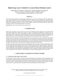
five-foot by five-foot test section. The tunnel, depicted in<br />
Figure 1, has a speed range from zero to about 10 meters/<br />
second (~22.5 mph). The relatively low speed makes it<br />
particularly suitable for flow visualization investigation where<br />
smoke, fog or other visualization techniques are required, and<br />
this is also the speed range of interest for micro-air vehicles.<br />
The tunnel is driven by a constant-speed motor with a<br />
variable pitch fan, changing the pitch of the fan to control the<br />
wind-speed.<br />
The tunnel is equipped with a positionable pitot-static tube<br />
and several high-accuracy differential pressure transducers for<br />
wind-speed measurement, as well as a 2-component Laser-<br />
Doppler Velocimetry (LDV) probe for measuring unsteady,<br />
local flow speeds with high accuracy. LDV is a non-intrusive<br />
method of measuring fluid velocity by optical means. Our<br />
system uses a water-cooled 5 Watt Coherent Innova 70C CW<br />
Argon-Ion Laser for a light source. The Coherent laser emits<br />
Figure 1. Schematic of the low-speed wind tunnel.<br />
several discrete colors (green - 514.5nm, blue - 488nm and<br />
purple 476nm), and a TSI Model 9201 ColorBurst<br />
multicolor beam separator is used to split the beams and<br />
frequency-shift one beam in each color. The green and blue<br />
beams, and their frequency shifted counterparts, are passed to<br />
a 2-component, 4-beam TSI Model 9832 probe through a<br />
fiber-optic cord. Probe beam spacing is 50mm, and lenses<br />
with focal lengths of 350mm and 750mm are available.<br />
Several methods are available for flow visualization. A Roscoe<br />
4500 fog machine is attached to a smoke rake which is placed<br />
outside the tunnel intake, and this provides sufficient flowseeding<br />
for the LDV measurements as well as flow visualization<br />
at higher tunnel speeds. A smoke-wire may be used to<br />
generate a sheet of smoke inside the test-section, a useful<br />
technique at lower tunnel speeds, as shown in Figure 3.<br />
Additionally, a laser light-sheet may be used with the Coherent<br />
laser, providing a bright, two-dimensional slice through<br />
the seeded flowfield.<br />
The Eidetics Water Tunnel<br />
We also have an Eidetics water tunnel, shown schematically<br />
in Figure 2, an ideal tool for flow visualization. The tunnel<br />
has a speed range between 0 and about 0.5 m/s, with a usable<br />
test section that is about 38cm square. It is a continuous flow<br />
tunnel with a 6:1 contraction ratio.<br />
Flow visualization is performed by injecting dye into the<br />
water. Multiple colors of dye can be used to identify different<br />
--continued on page 42<br />
Figure 2. Schematic of the Eidetics water tunnel.<br />
NPS Research page 9<br />
<strong>October</strong> <strong>2000</strong>