Capture Jet™ Hood with Side-Jet Technology - Halton
Capture Jet™ Hood with Side-Jet Technology - Halton
Capture Jet™ Hood with Side-Jet Technology - Halton
- TAGS
- capture
- halton
- www.halton.com

You also want an ePaper? Increase the reach of your titles
YUMPU automatically turns print PDFs into web optimized ePapers that Google loves.
KVI<br />
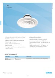
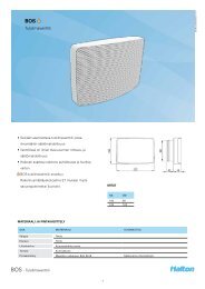
<strong>Capture</strong> <strong>Jet</strong> <strong>Hood</strong> <strong>with</strong> <strong>Side</strong>-<strong>Jet</strong> <strong>Technology</strong><br />
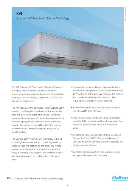
The KVI <strong>Capture</strong> <strong>Jet</strong> hood <strong>with</strong> <strong>Side</strong>-<strong>Jet</strong> technology<br />
is a highly efficient kitchen ventilation hood that<br />
removes contaminated air and excess heat emitted by<br />
cooking equipment, helping to provide a comfortable<br />
and clean environment.<br />
The KVI hood uses the advanced <strong>Halton</strong> <strong>Capture</strong> <strong>Jet</strong><br />
system, combining horizontal and vertical jets at the<br />
front and also on the sides of the hood to improve<br />
capture and containment of the air flows generated by<br />
the cooking equipment, even at the end of the line.<br />
Overall, the system requires 30 to 40% less exhaust<br />
air volume than traditional hoods do to remove an<br />
equal heat load.<br />
The <strong>Capture</strong> <strong>Jet</strong> <strong>with</strong> <strong>Side</strong>-<strong>Jet</strong> technology is based<br />
on the high entrainment of a compact, high-velocity<br />
capture air jet. The capture air jets efficiently induce<br />
ambient air at the critical front and side area of the<br />
hood, minimising the spillage of the contaminated air<br />
and maintaining good air quality in the chef’s work<br />
area.<br />
KVI - <strong>Capture</strong> <strong>Jet</strong> <strong>Hood</strong> <strong>with</strong> <strong>Side</strong>-<strong>Jet</strong> <strong>Technology</strong><br />
1<br />
• Improved indoor air quality for higher productivity<br />
<strong>with</strong> reduced energy use. <strong>Halton</strong>’s patented <strong>Capture</strong><br />
<strong>Jet</strong> <strong>with</strong> <strong>Side</strong>-<strong>Jet</strong> technology improves the capture<br />
and containment efficiency of the hood, thus<br />
reducing the exhaust air volume required.<br />
• Performance tested by a third party in accordance<br />
<strong>with</strong> the ASTM 1704 standard.<br />
• High-efficiency grease filtration using UL- and NSFclassified<br />
KSA multi-cyclone filters for removal of up<br />
to 95% of particles <strong>with</strong> a size of 8 microns or<br />
above.<br />
• Standard delivery that includes lighting, integrated<br />
<strong>Capture</strong> <strong>Jet</strong> fan, TAB (Testing and Balancing)<br />
taps, and balancing dampers that allow accurate and<br />
effective commissioning.<br />
• Stainless steel construction <strong>with</strong> seamless design<br />
for improved hygiene and fire safety.<br />
20/KVI/0000/0408/EN
9<br />
1<br />
10<br />
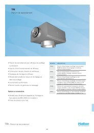
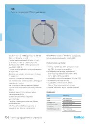
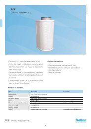
Construction<br />
3 4 5<br />
6 7 8<br />
The KVI kitchen canopy comprises a <strong>Capture</strong> <strong>Jet</strong> unit<br />
<strong>with</strong> side jets, a <strong>Capture</strong> <strong>Jet</strong> centrifugal fan<br />
(optional), an IP65 light fitting, adjustment dampers,<br />
airflow measurement taps and a KSA grease<br />
separator.<br />
All visible parts of the canopy are manufactured from<br />
polished stainless steel AISI 304 and the unexposed<br />
parts from galvanised steel. Joints on the lower edge<br />
are fully welded.<br />
A collection tray or a drain tap is fitted into the grease<br />
drain channel in order to enable the removal of the<br />
grease and dirt extracted by the KSA multi-cyclone<br />
separator.<br />
The <strong>Capture</strong> <strong>Jet</strong> air plenum is thermally insulated<br />
using non-fibre-releasing material to prevent vapours<br />
KVI - <strong>Capture</strong> <strong>Jet</strong> <strong>Hood</strong> <strong>with</strong> <strong>Side</strong>-<strong>Jet</strong> <strong>Technology</strong><br />
2<br />
2<br />
CODE DESCRIPTION<br />
1 Outer casing – visible parts in stainless steel AISI 304<br />
2 Exhaust air connection and adjustment damper<br />
3 <strong>Capture</strong> <strong>Jet</strong> fan and grille<br />
4 Access hatch<br />
5 Light fitting <strong>with</strong> electrical junction box<br />
6 <strong>Capture</strong> <strong>Jet</strong> nozzles<br />
7 KSA grease filter<br />
8 Grease collection tray or drain tap<br />
9 Thermal insulation<br />
10 Access hatch<br />
from condensing on the inner face of the canopy<br />
above the cooking equipment.<br />
Testing and balancing taps (TAB) for flow<br />
measurement are fitted to the exhaust plenum and<br />
the <strong>Capture</strong> <strong>Jet</strong> air plenum.<br />
The new <strong>Capture</strong> <strong>Jet</strong> family is manufactured in the<br />
form of modular sections. Large canopies are<br />
assembled using a combination of separate modules<br />
<strong>with</strong>out any beams between the modules, meaning<br />
that one long section is created, which is aesthetically<br />
preferable.<br />
The modular sections make transportation and site<br />
handling easier.<br />
20/KVI/0000/0408/EN
Modular Sections<br />
KVI - (1 closed end)<br />
QUICK DATA<br />
KVI - (2 opened ends)<br />
KVI - <strong>Capture</strong> <strong>Jet</strong> <strong>Hood</strong> <strong>with</strong> <strong>Side</strong>-<strong>Jet</strong> <strong>Technology</strong><br />
3<br />
KVI - (1 closed end)<br />
Recommended Exhaust air volume Recommended <strong>Capture</strong> <strong>Jet</strong> air volume<br />
(<strong>with</strong> width = 1300)<br />
L1 (section length) L l/s m3 /h l/s m3 /h<br />
1500 1600 389 … 602 1400 … 2169 27 97<br />
2000 2100 519 … 803 1867 … 2892 31 112<br />
2500 2600 648 … 1004 2333 … 3615 35 127<br />
5000 5100 1296 … 2008 4667 … 7230 56 202<br />
7500 7600 1945 … 3012 7000 … 10845 77 277<br />
10000 10100 2593 … 4017 9334 … 14460 98 352<br />
20/KVI/0000/0408/EN
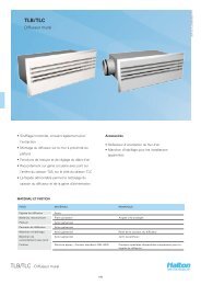
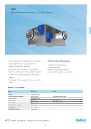
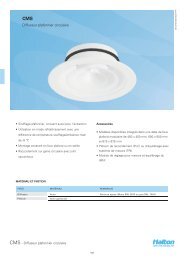
Function<br />
The kitchen canopy above cooking appliances contains<br />
the rising warm air and contaminants (A).<br />
The <strong>Capture</strong> <strong>Jet</strong> (B) increases the efficiency of<br />
capture of the smoke and contaminated air at both the<br />
face and sides for enhanced performance at the end<br />
of the cooking line and directs the contaminated air<br />
Accessories<br />
• Cover Boards – where canopies are below ceiling<br />
level<br />
• Infill Panels<br />
• KSA grease filters<br />
• Blind filter in stainless steel<br />
KVI - <strong>Capture</strong> <strong>Jet</strong> <strong>Hood</strong> <strong>with</strong> <strong>Side</strong>-<strong>Jet</strong> <strong>Technology</strong><br />
4<br />
Heat spilling <strong>Capture</strong> &<br />
containment<br />
towards the KSA grease separator (C), where the<br />
grease particles and other impurities are separated<br />
from the exhaust air using the cyclone separation<br />
principle. Grease and contaminants that have been<br />
removed flow into a drain channel and towards the<br />
collection tap/tray (D).<br />
• Non-standard spigots sizes and position<br />
• Canopy cut outs to fit around columns<br />
• Exhaust/supply roof in stainless steel<br />
• U profile for hanging<br />
20/KVI/0000/0408/EN
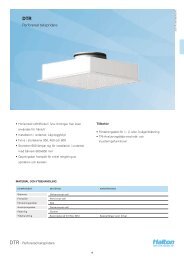
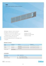
DIMENSIONS (mm)<br />
KVI - (2 closed ends)<br />
L 1100 … 3100<br />
B 1200 … 1700<br />
H 555<br />
D2 315<br />
G 250<br />
J 170<br />
Note: The dimensions above are for modular sections only;<br />
larger canopies are assembled using a combination of separate<br />
modules, which makes transportation and site handling easier.<br />
Light<br />
A 25<br />
F 175<br />
E 450<br />
I 720 (L1 1500 2x36W)<br />
LOCATION OF CONNECTIONS (mm)<br />
For typical sizes<br />
Exhaust <strong>Capture</strong> <strong>Jet</strong><br />
1 Ø315 2 Ø315 1 Ø160<br />
L N N1 M M1 N<br />
1600 L/2 L1/2 375 325 L/2<br />
2100 L/2 L1/2 500 450 L/2<br />
2600 L/2 L1/2 500 450 L/2<br />
3100 L/2 L1/2 500 450 L/2<br />
WEIGHT (KG)<br />
L/B 1300 1500 1700<br />
1600 103 109 115<br />
2100 120 126 132<br />
2600 138 144 150<br />
3100 156 162 168<br />
KVI - <strong>Capture</strong> <strong>Jet</strong> <strong>Hood</strong> <strong>with</strong> <strong>Side</strong>-<strong>Jet</strong> <strong>Technology</strong><br />
5<br />
N<br />
Optional spigot<br />
Ø160<br />
KVI - (2 closed ends)<br />
M<br />
J<br />
E<br />
F<br />
A<br />
B<br />
I<br />
Wall<br />
ØD2<br />
G<br />
Wall<br />
M1<br />
M1<br />
50<br />
H<br />
50<br />
N1<br />
L1<br />
L<br />
20/KVI/0000/0408/EN
DIMENSIONS (mm)<br />
KVI - (1 closed end)<br />
L2 1050 … 3050<br />
B 1200 … 1700<br />
H 555<br />
D2 315<br />
G 250<br />
J 170<br />
Note: The dimensions above are for modular sections only;<br />
larger canopies are assembled using a combination of separate<br />
modules, which makes transportation and site handling easier.<br />
Light<br />
A 25<br />
F 175<br />
E 450<br />
I 720 (L1 1500 2x36W)<br />
LOCATION OF CONNECTIONS (mm)<br />
For typical sizes<br />
WEIGHT (KG)<br />
Exhaust <strong>Capture</strong> <strong>Jet</strong><br />
1 Ø315 2 Ø315 1 Ø160<br />
L2 N1 M1 N1<br />
1550 (L2-50)/2 325 (L2-50)/2<br />
2050 (L2-50)/2 450 (L2-50)/2<br />
2550 (L2-50)/2 450 (L2-50)/2<br />
3050 (L2-50)/2 450 (L2-50)/2<br />
L2/B 1300 1500 1700<br />
1550 98 104 110<br />
2050 115 121 127<br />
2550 133 139 145<br />
3050 151 157 163<br />
KVI - <strong>Capture</strong> <strong>Jet</strong> <strong>Hood</strong> <strong>with</strong> <strong>Side</strong>-<strong>Jet</strong> <strong>Technology</strong><br />
6<br />
Optional spigot<br />
Ø160<br />
KVI - (1 closed end)<br />
N1<br />
M<br />
J<br />
E<br />
F<br />
A<br />
B<br />
I<br />
Wall<br />
ØD2<br />
G<br />
M1<br />
M1<br />
H<br />
50<br />
N1<br />
L1<br />
L2<br />
20/KVI/0000/0408/EN
DIMENSIONS (mm)<br />
KVI - (2 open ends)<br />
L1 1000 … 3000<br />
B 1200 … 1700<br />
H 555<br />
D2 315<br />
G 250<br />
J 170<br />
Note: The dimensions above are for modular sections only;<br />
larger canopies are assembled using a combination of separate<br />
modules, which makes transportation and site handling easier.<br />
Light<br />
A 25<br />
F 175<br />
E 450<br />
I 720 (L1 1500 2x36W)<br />
LOCATION OF CONNECTIONS (mm)<br />
For typical sizes<br />
Exhaust <strong>Capture</strong> <strong>Jet</strong><br />
1 Ø315 2 Ø315 1 Ø160<br />
L1 N1 M1 N1<br />
1500 L1 /2 325 L1 /2<br />
2000 L1 /2 450 L1 /2<br />
2500 L1 /2 450 L1 /2<br />
3000 L1 /2 450 L1 /2<br />
WEIGHT (KG)<br />
L1/B 1300 1500 1700<br />
1500 93 99 105<br />
2000 110 116 122<br />
2500 128 134 140<br />
3000 146 152 158<br />
KVI - <strong>Capture</strong> <strong>Jet</strong> <strong>Hood</strong> <strong>with</strong> <strong>Side</strong>-<strong>Jet</strong> <strong>Technology</strong><br />
7<br />
KVI - (2 opened ends)<br />
N1<br />
Optional spigot<br />
Ø160<br />
J<br />
E<br />
F<br />
A<br />
B<br />
I<br />
ØD2<br />
G<br />
M1<br />
M1<br />
H<br />
N1<br />
L1<br />
20/KVI/0000/0408/EN
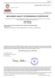
Pressure drop and sound data, exhaust<br />
H= 555<br />
∆Ptab = Pressure loss of filters measured<br />
from Measuring tap<br />
∆Pst = Total exhaust static pressure loss<br />
30,70,100 = Damper opening in %<br />
Section-1000<br />
pst<br />
[Pa]<br />
pst<br />
[Pa]<br />
300<br />
200<br />
100<br />
50<br />
30<br />
20<br />
300<br />
200<br />
100<br />
50<br />
30<br />
20<br />
30<br />
35<br />
300 400 500<br />
40<br />
45<br />
50<br />
55<br />
30<br />
70<br />
100<br />
qv [l/s]<br />
1000 2000 3000 qv [m3/h]<br />
L r = 8 dB<br />
30<br />
35<br />
LpA dB(A)<br />
40<br />
200 300 400 500<br />
800<br />
qv [l/s]<br />
500 720<br />
1000 1440 1800 qv [m3/h]<br />
L r = 8 dB<br />
LpA dB(A)<br />
KVI - <strong>Capture</strong> <strong>Jet</strong> <strong>Hood</strong> <strong>with</strong> <strong>Side</strong>-<strong>Jet</strong> <strong>Technology</strong><br />
45<br />
50<br />
30<br />
55<br />
70<br />
100<br />
8<br />
Section-1500<br />
pst<br />
[Pa]<br />
pst<br />
[Pa]<br />
300<br />
200<br />
100<br />
50<br />
30<br />
20<br />
300<br />
200<br />
100<br />
50<br />
30<br />
20<br />
L r = 8 dB<br />
Section-2000 Section-2500<br />
400<br />
L r = 8 dB<br />
30<br />
�P st<br />
�P tab<br />
35<br />
LpA dB(A)<br />
40<br />
45<br />
300 500<br />
50<br />
30<br />
55<br />
70<br />
100<br />
qv [l/s]<br />
1000 2000 qv [m3/h]<br />
30<br />
1800<br />
500<br />
35<br />
LpA dB(A)<br />
40<br />
45<br />
50<br />
600<br />
1000<br />
30<br />
55<br />
70<br />
100<br />
qv [l/s]<br />
2000 3000 qv [m3/h]<br />
20/KVI/0000/0408/EN
Section-3000<br />
pst<br />
[Pa]<br />
300<br />
200<br />
100<br />
50<br />
30<br />
20<br />
L r = 8dB<br />
30<br />
LpA dB(A)<br />
35<br />
40<br />
45<br />
500 600<br />
1000<br />
50<br />
1200<br />
30<br />
55<br />
70<br />
100<br />
qv [l/s]<br />
2000 3000 5000 qv [m3/h]<br />
T.A.B. / Exhaust air-flow rate adjustment<br />
Recommended pressure TAB 50-120 Pa<br />
�p<br />
TAB<br />
" w.g.<br />
0.8<br />
0.5<br />
0.4<br />
0.3<br />
0.2<br />
0.12<br />
Pa<br />
200<br />
120<br />
100<br />
50<br />
30<br />
70<br />
80<br />
90<br />
100<br />
120<br />
140 160 180 200<br />
9<br />
300<br />
400<br />
500 600 700 800 900 1000<br />
20<br />
150 200 250 300 400 500 600 700<br />
1000<br />
1500 2000 2500 2900<br />
250<br />
300<br />
400<br />
KSA active section 500 mm<br />
KVI - <strong>Capture</strong> <strong>Jet</strong> <strong>Hood</strong> <strong>with</strong> <strong>Side</strong>-<strong>Jet</strong> <strong>Technology</strong><br />
500<br />
600<br />
1000<br />
KVI K-FACTOR CHART, EXHAUST<br />
KSA (Number of filters) K factor (m 3 /h) K factor (l/s)<br />
1 68,7 19,1<br />
2 137,5 38,2<br />
3 204,7 56,9<br />
4 270,9 75,2<br />
5 339,5 94,3<br />
6 408,4 113,4<br />
1500<br />
1000<br />
2000<br />
1500<br />
2000<br />
3000<br />
2500<br />
4000<br />
1200<br />
3000<br />
5000<br />
l/s<br />
cfm<br />
m³/h<br />
20/KVI/0000/0408/EN
Suggested specifications<br />
The kitchen hood shall be constructed from 1.0-mm<br />
AISI 304 stainless steel.<br />
The kitchen hood shall be supplied complete <strong>with</strong><br />
<strong>Capture</strong> <strong>Jet</strong> technology, high-efficiency multi-cyclone<br />
grease filters, pressure measurement taps, exhaust air<br />
spigots <strong>with</strong> adjustment dampers, and a fluorescent<br />
light fitting <strong>with</strong> installation hatch.<br />
The size shall be as indicated in the drawings.<br />
Outer casing<br />
• Outer casing panels are constructed from AISI 304<br />
stainless steel in a brushed satin finish in a modular<br />
construction. The joints of the lower edge shall be<br />
fully welded to be liquid-tight, avoiding harmful<br />
dripping of condensation. All exposed welds are<br />
ground and polished to the original finish of the<br />
metal.<br />
• The bottom edge of the exhaust plenum should be<br />
aerodynamically designed (no flat surface or<br />
bounce).<br />
• Canopy ends shall be of double-sidewall construction<br />
(no single wall permitted).<br />
Exhaust<br />
• The exhaust air flow will be based on the convective<br />
heat generated by the appliances underneath each<br />
canopy. Submittal shall include convective heat<br />
calculations based on the input power of the<br />
appliance served.<br />
• The hood’s mounting height shall be in accordance<br />
<strong>with</strong> the drawings supplied, as a moderate increase<br />
in exhaust rate is required if the hood is installed<br />
higher than designed.<br />
KVI - <strong>Capture</strong> <strong>Jet</strong> <strong>Hood</strong> <strong>with</strong> <strong>Side</strong>-<strong>Jet</strong> <strong>Technology</strong><br />
10<br />
<strong>Capture</strong> <strong>Jet</strong> <strong>with</strong> side-jet technology<br />
• The hood shall be designed <strong>with</strong> <strong>Capture</strong> <strong>Jet</strong><br />
technology and <strong>Side</strong>-<strong>Jet</strong> technology to reduce the<br />
exhaust air flow rate required and to improve the<br />
capture and containment efficiency of the hood not<br />
only at the front but also on the sides of the canopy,<br />
while reducing energy consumption. The <strong>Capture</strong><br />
<strong>Jet</strong> air shall be introduced through a special<br />
discharge panel and shall not exceed 10% of the<br />
calculated exhaust air flow. The <strong>Capture</strong> <strong>Jet</strong><br />
discharge velocity shall be, at minimum, 8 m/s. Slotor<br />
grille-type discharge shall not be used. The<br />
<strong>Capture</strong> <strong>Jet</strong> chamber is to be insulated.<br />
• The hood shall be supplied <strong>with</strong> a <strong>Capture</strong> <strong>Jet</strong> fan<br />
to provide the required air flow at the indicated<br />
static pressure. The fan is to be provided by the<br />
hood manufacturer, so an additional supply air<br />
system is not required for the <strong>Capture</strong> <strong>Jet</strong> system.<br />
Grease filters<br />
• The hood shall be equipped <strong>with</strong> a KSA-model multicyclone<br />
stainless steel grease extractor. The grease<br />
extraction efficiency is 93% for particles <strong>with</strong> a<br />
diameter of 5 microns and 98% for those <strong>with</strong> a<br />
diameter of 15 microns or larger, as tested by an<br />
independent testing laboratory. The pressure loss<br />
over the extractor shall not exceed 120 Pa at the<br />
flow rates calculated. Sound levels shall not exceed<br />
an LpA rating of 50 dB(A). The filter shall be NSFand<br />
UL-classified. Baffle- or slot-type grease<br />
extractors shall not be used.<br />
TAB ports and air flow balancing<br />
• The air flows through the KSA separator and the<br />
<strong>Capture</strong> <strong>Jet</strong> air chamber are to be determined via<br />
the integral TAB ports mounted in the hood. The air<br />
flows are to be determined by the pressure vs. air<br />
flow curves supplied by <strong>Halton</strong>.<br />
• The replacement air shall be delivered <strong>with</strong> a supply<br />
control damper of type MSM.<br />
• The spigot connections for supply and extracted air<br />
shall be supplied <strong>with</strong> a sealing gasket and air-flowbalancing<br />
damper plate.<br />
20/KVI/0000/0408/EN
Light fixtures<br />
• Each canopy shall be provided <strong>with</strong> a fluorescent<br />
light fixture to provide approx. 500 lux at the cooking<br />
appliances work surface. The light is protected <strong>with</strong><br />
a stainless steel hatch <strong>with</strong> plain milled finish,<br />
surrounded by a tempered-glass light diffuser (the<br />
heat tolerance of the glass shall be -40 to 300 ˚C).<br />
The hatch shall be hinged and held in position <strong>with</strong><br />
screws.<br />
Fire suppression system<br />
• The kitchen hood fire extinguishing system shall<br />
protect the kitchen hood against grease fires<br />
through a completely automatic fire control system<br />
of the wet chemical type. The fire detection system<br />
shall be capable of detecting fire in the hood, duct,<br />
or surface equipment and shall automatically<br />
discharge liquid extinguishing agent into the plenum<br />
chamber, exhaust duct collar, and cooking appliance<br />
areas to eliminate the possibility of re-ignition or<br />
re-flash. System components shall include a springloaded<br />
release mechanism, agent tank brass nozzles<br />
<strong>with</strong> blow-off caps and stainless steel appliance<br />
drops, a fusible link detector, wall-mounted<br />
emergency pull stations, a wall-mounted automan<br />
and cabinet, and a mechanical gas valve installed in<br />
the gas line serving the cooking equipment (valve<br />
provided by the fire protections system<br />
manufacturer and installed in the gas line by a<br />
plumber). The system’s installation shall be<br />
performed by an authorised representative of the<br />
system manufacturer and conform to UL 300<br />
requirements and local codes.<br />
Type: KVI Manufacturer: <strong>Halton</strong><br />
KVI - <strong>Capture</strong> <strong>Jet</strong> <strong>Hood</strong> <strong>with</strong> <strong>Side</strong>-<strong>Jet</strong> <strong>Technology</strong><br />
11<br />
20/KVI/0000/0408/EN
Product code<br />
SAP product code KVI_3<br />
WE = Closed end(s)<br />
2 = 2 walls<br />
R = Right side wall<br />
L = Left side wall<br />
N = No wall<br />
H = Height<br />
555-555<br />
555-400<br />
L = Lenght<br />
If WE = N L = 1000, 1050,……3000<br />
If WE = R or L L = 1050, 1100,……3050<br />
If WE = 2 L = 1100, 1150,..….3100<br />
LF = Light fitting<br />
T5 T5<br />
T8 T8<br />
N No<br />
LC = Light color<br />
830 830<br />
840 840<br />
930 930<br />
940 940<br />
B = Width<br />
If LF = T5 or T8 B = 1200,1250,……..1700<br />
If LF = N B = 1000,1050,……..1700<br />
NB = Number of blind filters<br />
NB = 0,1,2,3,4,5,6<br />
EC = Number of exhaust connections<br />
1 = 1 spigot<br />
2 = 2 spigots<br />
3 = 3 spigots<br />
N = no spigot<br />
ED = Exhaust damper<br />
1 = Yes<br />
N = No<br />
KVI - <strong>Capture</strong> <strong>Jet</strong> <strong>Hood</strong> <strong>with</strong> <strong>Side</strong>-<strong>Jet</strong> <strong>Technology</strong><br />
12<br />
CJ = <strong>Capture</strong> jet fan<br />
5 = Nothing (no CJ fan, no connection<br />
plenum...)<br />
6 = CJ fan + grille<br />
7 = CJ fan + spigot Ø160<br />
8 = Spigot Ø160 + damper type MSM<br />
(No CJ fan)<br />
CD = Canopy drain<br />
D = Drain tap<br />
C = Collection tray<br />
HS = Hanging system<br />
S = Standard<br />
U = U profile<br />
M=Material<br />
AS = Full stainless steel<br />
AT = Full stainless steel 1,2 mm<br />
CS = Standard<br />
CT = Standard 1,2 mm<br />
Sub product<br />
KB (cover board)<br />
KI (Infill panel)<br />
Code example<br />
KVI/N-1000-1000-555, LF=T5, LC=830, NB=0, EC=N,<br />
ED=N, CJ=6, CD=D, HS=S, MA=CS, ZT=N<br />
20/KVI/0000/0408/EN