imaging of fractures and faults inside granite basement - CGG Veritas
imaging of fractures and faults inside granite basement - CGG Veritas
imaging of fractures and faults inside granite basement - CGG Veritas

You also want an ePaper? Increase the reach of your titles
YUMPU automatically turns print PDFs into web optimized ePapers that Google loves.
IMAGING OF FRACTURES AND FAULTS INSIDE GRANITE BASEMENT USING<br />
CONTROLLED BEAM MIGRATION<br />
Don Pham, Jason Sun, James Sun*, <strong>and</strong> Qingbing Tang, <strong>CGG</strong><strong>Veritas</strong>, Singapore<br />
Graeme Bone <strong>and</strong> Nguyen Truong Giang, CuuLong JOC, Vietnam<br />
james.sun@cggveritas.com<br />
Summary<br />
In this paper, we present a reprocessing case study that<br />
applied the latest processing technologies to improve the<br />
seismic <strong>imaging</strong> <strong>inside</strong> the <strong>granite</strong> <strong>basement</strong> reservoir. The<br />
highlight <strong>of</strong> this effort is the application <strong>of</strong> the latest<br />
Controlled Beam Migration (CBM) technology, <strong>and</strong> a stack<br />
sweep method for updating velocity <strong>inside</strong> the <strong>basement</strong>.<br />
Introduction<br />
The current study area is in the Cuu Long Basin, <strong>of</strong>fshore<br />
Vietnam. In this area, the fractured <strong>granite</strong> <strong>basement</strong> forms<br />
an excellent reservoir rock, <strong>and</strong> is the main target <strong>of</strong><br />
exploration <strong>and</strong> development activities (Nguyen <strong>and</strong> Hung,<br />
2004). It is therefore important to image the <strong>granite</strong><br />
<strong>basement</strong> with its <strong>fractures</strong> using seismic methods.<br />
However, past effort <strong>of</strong> <strong>imaging</strong> has met with difficulties.<br />
Two <strong>of</strong> the main challenges are the poor signal-to-noise<br />
ratio <strong>inside</strong> the <strong>basement</strong> <strong>and</strong> the <strong>imaging</strong> <strong>of</strong> the steeply<br />
dipping <strong>fractures</strong>. In 2002, a study was carried out in the<br />
area using Kirchh<strong>of</strong>f prestack depth migration, which<br />
included horizon-based model building up to the <strong>basement</strong><br />
<strong>and</strong> constant velocity sweep below the top <strong>of</strong> <strong>basement</strong>.<br />
Even with this effort, it was difficult to interpret because<br />
the image was contaminated with noise. In particular, it<br />
was hard to distinguish the vaguely visible steeply dipping<br />
<strong>fractures</strong> from Kirchh<strong>of</strong>f migration artefacts.<br />
With recent advances in <strong>imaging</strong> technology <strong>and</strong> velocity<br />
model building tools, we reprocessed the same data through<br />
prestack depth migration, <strong>and</strong> achieved significant<br />
improvements in signal-to-noise ratio <strong>and</strong> steep dip<br />
<strong>imaging</strong> <strong>inside</strong> the <strong>basement</strong>. We present the methodology<br />
<strong>and</strong> results in this abstract.<br />
Methodology<br />
Data preparation<br />
Prior to migration, the acquired seismic data was processed<br />
through linear noise removal, demultiple, <strong>and</strong> fold <strong>and</strong><br />
<strong>of</strong>fset regularization. It is extremely important to preserve<br />
dipping primary energy in data preparation, especially at<br />
the stage <strong>of</strong> linear noise removal.<br />
Velocity model building <strong>and</strong> update<br />
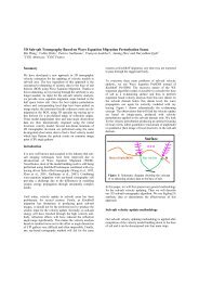
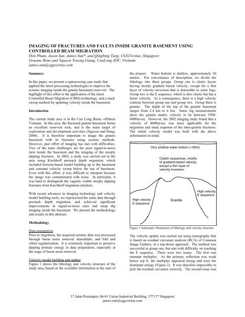
Figure 1 shows the lithology <strong>and</strong> velocity structure <strong>of</strong> the<br />
study area, based on the available information at the start <strong>of</strong><br />
the project. Water bottom is shallow, approximately 50<br />
meters. For convenience <strong>of</strong> description, we divide the<br />
lithology into three groups. Group one is clastic layers<br />
having mostly gradient based velocity, except for a thin<br />
layer <strong>of</strong> velocity inversion that is detectable in sonic logs.<br />
Group two is the E sequence, which is also clastic but has a<br />
faster velocity. As a consequence, there is a high velocity<br />
contrast between group one <strong>and</strong> group two. Group three is<br />
<strong>granite</strong>. The depth <strong>of</strong> the top <strong>of</strong> the <strong>granite</strong> <strong>basement</strong><br />
ranges from 2.4 km to 6 km. Sonic log measurements<br />
show the <strong>granite</strong> matrix velocity to be between 5500-<br />
6000m/sec. However, the 2002 <strong>imaging</strong> study found that a<br />
velocity <strong>of</strong> 4600m/sec was more applicable for the<br />
migration <strong>and</strong> stack response <strong>of</strong> the intra-<strong>granite</strong> <strong>fractures</strong>.<br />
The initial velocity model was built with the above<br />
information in mind.<br />
High velocity<br />
E sequence<br />
Very shallow water bottom (~50m)<br />
Clastic sequences, mostly<br />
<strong>of</strong> gradient-based velocity,<br />
except a thin layer <strong>of</strong><br />
velocity inversion<br />
Granite<br />
High velocity<br />
E sequence<br />
Figure 1 Schematic illustration <strong>of</strong> lithology <strong>and</strong> velocity structure<br />
The velocity update was carried out using tomography that<br />
is based on residual curvature analysis (RCA) <strong>of</strong> Common<br />
Image Gathers, in a top-down approach. The method was<br />
successful in group one, but met with difficulty on reaching<br />
the E sequence. There were two issues. The first was<br />
remnant multiples. As the primary reflection was weak<br />
below top E, the multiples appeared strong <strong>and</strong> were the<br />
dominant energy (Figure 2). It was therefore impossible to<br />
pick the residual curvature correctly. The second issue was<br />
37 Jalan Pemimpin, 06-01 Union Industrial Building, 577177 Singapore<br />
james.sun@cggveritas.com
in the limitation <strong>of</strong> RCA tomography itself. The residual<br />
curvature <strong>of</strong> CIG is less sensitive to velocity perturbation at<br />
deeper depth.<br />
Figure 2. A stack section <strong>and</strong> some common image gathers (CIG)<br />
near a highlighted location. Red: top E. Yellow: top <strong>of</strong> the<br />
<strong>basement</strong>. The multiples are stronger than primaries below top E.<br />
To continue the velocity update into the E sequence <strong>and</strong> the<br />
<strong>granite</strong> <strong>basement</strong>, we resorted to a stack sweep method that<br />
was developed for sub-salt velocity update in the Gulf <strong>of</strong><br />
Mexico. We took the top E horizon as the upper boundary<br />
<strong>of</strong> the stack sweep (Figure 3). The velocity below top E<br />
was smoothed <strong>and</strong> used as the reference velocity, or 100%<br />
velocity. Six other velocities were generated by scaling the<br />
reference velocity below top E with 83.5%, 89%, 94.5%,<br />
105.5%, 110% <strong>and</strong> 116.5%, respectively. The seven<br />
velocities were used to generate seven CBM (to be<br />
introduced later) stacks. We then swept through the seven<br />
stacks at each location <strong>and</strong> depth, <strong>and</strong> picked the preferred<br />
stack (Figure 4). The criterion for picking was based on<br />
both the quality <strong>of</strong> the signal <strong>and</strong> the geologic plausibility<br />
<strong>of</strong> the structure, so it was necessary to be done by or with<br />
the help <strong>of</strong> an interpreter. After all locations were picked,<br />
the picks were smoothed, <strong>and</strong> then fed into a 3-D<br />
tomography program to compute the final velocity (Figure<br />
5).<br />
Migration<br />
Both Kirchh<strong>of</strong>f <strong>and</strong> Controlled Beam Migration (CBM)<br />
were used in the final migration. Kirchh<strong>of</strong>f migration was<br />
Imaging in Granite Basement<br />
run to image shallow sections <strong>and</strong> to facilitate the AVO<br />
analysis, while CBM was used to image the top <strong>of</strong> the<br />
<strong>basement</strong> <strong>and</strong> the <strong>fractures</strong> <strong>inside</strong> the <strong>basement</strong>.<br />
CBM has an advantage <strong>of</strong> enhancing signal-to-noise ratios<br />
<strong>and</strong> <strong>imaging</strong> steeply dipping events. In a medium <strong>of</strong><br />
complex velocity, a subsurface point may have multiarrivals.<br />
A conventional Kirchh<strong>of</strong>f migration is a singlearrival<br />
migration algorithm, representing a high-frequency<br />
approximation to the acoustic wave equation. When multiarrivals<br />
occur, it has to select one <strong>of</strong> the arrivals depending<br />
on the specified criteria. This can result in poor <strong>imaging</strong>.<br />
Wave Equation Migration does not use ray paths to<br />
represent the propagation <strong>of</strong> wave fronts, <strong>and</strong> thus accounts<br />
for all arrivals. It produces cleaner images; but it does not<br />
image steeply dipping events well. CBM has the advantage<br />
<strong>of</strong> Kirchh<strong>of</strong>f migration <strong>and</strong> Wave Equation Migration. It<br />
h<strong>and</strong>les multi-arrivals, resulting in a cleaner image than<br />
Kirchh<strong>of</strong>f migration, <strong>and</strong> preserves the steep dips.<br />
Results <strong>and</strong> discussion<br />
The Kirchh<strong>of</strong>f migration image in the current study is<br />
better than the 2002 Kirchh<strong>of</strong>f image. However, for<br />
<strong>basement</strong> <strong>imaging</strong>, the major improvement came from<br />
CBM. A comparison <strong>of</strong> 2002 Kirchh<strong>of</strong>f migration <strong>and</strong> the<br />
current (2006) CBM migration is shown in Figures 6 to 8.<br />
The <strong>fractures</strong> that were barely visible in Kirchh<strong>of</strong>f<br />
migration were clearly imaged with CBM. The top <strong>of</strong> the<br />
<strong>basement</strong> is also better focused with CBM.<br />
Conclusions<br />
We have presented a case study using Controlled Beam<br />
Migration (CBM) to image the top <strong>of</strong> the <strong>basement</strong> <strong>and</strong> the<br />
<strong>fractures</strong> <strong>inside</strong> the <strong>basement</strong>. The image quality <strong>of</strong> CBM<br />
is superior to that <strong>of</strong> Kirchh<strong>of</strong>f migration.<br />
Acknowledgements<br />
We thank Cuu Long JOC <strong>and</strong> <strong>CGG</strong><strong>Veritas</strong> for permission<br />
to publish this work. We also thank Xie Yi, Pauline Khoo<br />
<strong>and</strong> Jiao Chenghai for their help in this study.<br />
References<br />
Nguyen, D. <strong>and</strong> Hung, V., 2003, Hydrocarbon Geology <strong>of</strong><br />
Cuu Long Basin – Offshore Vietnam. Presentation at the<br />
AAPG International Conference, Barcelona, Spain,<br />
September 21-24, 2003.
Figure 3. 3D view <strong>of</strong> the Top E horizon. Stack sweep starts below the top E horizon<br />
Figure 4. A snap shot <strong>of</strong> the stack sweep window.<br />
37 Jalan Pemimpin, 06-01 Union Industrial Building, 577177 Singapore<br />
james.sun@cggveritas.com
Imaging in Granite Basement<br />
Figure 5. A section <strong>of</strong> the final velocity model, after stack sweep velocity update.<br />
Figure 6. Comparison <strong>of</strong> 2002 <strong>and</strong> 2006 depth migration on a vertical section
Imaging in Granite Basement<br />
Figure 7. Comparison <strong>of</strong> 2002 <strong>and</strong> 2006 depth migration on a vertical section.<br />
Figure 8. Comparison <strong>of</strong> 2002 <strong>and</strong> 2006 depth migration on time slices.