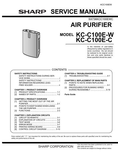
SERVICE MANUAL AIR PURIFIER KC-C100E-W ... - Y. Servis Girişi
SERVICE MANUAL AIR PURIFIER KC-C100E-W ... - Y. Servis Girişi
SERVICE MANUAL AIR PURIFIER KC-C100E-W ... - Y. Servis Girişi

You also want an ePaper? Increase the reach of your titles
YUMPU automatically turns print PDFs into web optimized ePapers that Google loves.
TopPage<br />
<strong>KC</strong><strong>C100E</strong>W<br />
<strong>SERVICE</strong> <strong>MANUAL</strong><br />
CONTENTS<br />
SAFETY INSTRUCTIONS<br />
SAFETY INSTRUCTIONS DURING SER-<br />
VICE WORK.......................................................i<br />
SAFETY INSTRUCTIONS .................................i<br />
INFORMATION REGARDING LEAD-<br />
FREE SOLDER.................................................ii<br />
CHAPTER 1. PRODUCT OVERVIEW<br />
[1] PRODUCT SPECIFICATIONS...................... 1-1<br />
[2] NAMES OF PARTS....................................... 1-2<br />
CHAPTER 2. PRODUCT OVERVIEW<br />
[1] GETTING THE MOST OUT OF THE <strong>AIR</strong><br />
<strong>PURIFIER</strong> ..................................................... 2-1<br />
[2] POINTS TO KEEP IN MIND WHEN USING<br />
THE <strong>AIR</strong> <strong>PURIFIER</strong> ...................................... 2-2<br />
[3] FUNCTIONS ................................................. 2-3<br />
CHAPTER 3. EXPLANATION CIRCUITS<br />
[1] CIRCUIT SCHEMATIC.................................. 3-1<br />
[2] EXPLANATION OF CIRCUITS ..................... 3-2<br />
[3] TEST MODE ................................................. 3-6<br />
[4] ERROR MODE ............................................. 3-7<br />
[5] PRINTED WIRING BOARD .......................... 3-9<br />
[6] CONTROL CIRCUIT DIAGRAM ................. 3-10<br />
MODEL<br />
SX736<strong>KC</strong><strong>C100E</strong>WC<br />
CHAPTER 4. TROUBLESHOOTING GUIDE<br />
[1] TROUBLESHOOTING ..................................4-1<br />
CHAPTER 5. REPLACEMENT OF MAIN PARTS<br />
[1] POINTS TO NOTE WHEN REPLACING<br />
PARTS ...........................................................5-1<br />
[2] PROCEDURES FOR RUNNING WIRES<br />
DURING REASSEMBLY .............................5-19<br />
Parts Guide<br />
<strong>AIR</strong> <strong>PURIFIER</strong><br />
<strong>KC</strong>-<strong>C100E</strong>-W<br />
<strong>KC</strong>-<strong>C100E</strong>-C<br />
In the interests of user-safety<br />
(Required by safety regulations in<br />
some countries) the set should<br />
be restored to its original condition<br />
and only parts identical to<br />
those specified should be used.<br />
Parts marked with " " are important for maintaining the safety of the set. Be sure to replace these parts with specified ones for maintaining the<br />
safety and performance of the set.<br />
This document has been published to be used for<br />
after sales service only.<br />
The contents are subject to change without notice.
<strong>KC</strong><strong>C100E</strong>W<br />
<strong>KC</strong><strong>C100E</strong>W<br />
SAFETY INSTRUCTIONS<br />
Service Manual<br />
SAFETY INSTRUCTIONS DURING <strong>SERVICE</strong> WORK<br />
Before disassembling a product, verify that the plug has been removed from the power outlet. Exercise caution while working.<br />
�SAFETY INSTRUCTIONS PRIOR TO WORK<br />
DANGER<br />
Be sure to remove the plug from the power outlet before beginning<br />
work (danger of electrical shock).<br />
�SAFETY INSTRUCTIONS DURING WORK<br />
WARNING<br />
Parts in the parts guide indicated by are important for safety.<br />
When replacing one of these parts, be sure to use only the specified<br />
part to ensure safety (danger of smoke, fire, and/or electrical<br />
shock).<br />
CAUTIONS<br />
Run lead wires so that they do not touch edges of parts (danger of<br />
electrical shock due to wire breakage).<br />
Exercise caution when working near and handling the edges of<br />
metal parts (danger of cutting your hand).<br />
Run lead wires in their original positions using ties to prevent them<br />
from touching movable parts (danger of electrical shock and fire due<br />
to wire breakage).<br />
After replacing a part, verify that the wiring has been performed correctly<br />
and securely in accordance with the schematic (danger of<br />
smoke and fire).<br />
�SAFETY INSTRUCTIONS FOLLOWING WORK<br />
WARNING<br />
Following repair or replacement, be sure to use an insulation resistance<br />
tester to test the insulation resistance. If the insulation resistance<br />
is 10 MΩ or less, inspect each part and replace failed parts<br />
(danger of electrical shock).<br />
Before plugging in the plug, wipe between the prongs with a dry<br />
cloth. Insert the plug firmly into the outlet. If there is dust or moisture<br />
on the plug, admonish the customer (danger of fire).<br />
CAUTIONS<br />
Following service, verify that no screws, tools, or debris have fallen<br />
into the unit before turning on the power (danger of electrical<br />
shock).<br />
Remove dust from the filter. If a large amount of dust has accumulated,<br />
instruct the customer that it is necessary to remove the dust<br />
(danger of abnormal overheating).<br />
SAFETY INSTRUCTIONS<br />
WARNING<br />
Use only a 220-240 VAC power source.<br />
Danger of fire and electrical shock.<br />
Do not use the product if the power cord or plug is damaged or the<br />
connection to the wall outlet is loose.<br />
Danger of fire, electrical shock, and short-circuiting.<br />
Do not damage, modify, excessively bend, pull, twist, or bind the<br />
power cord. Do not place heavy objects on the cord or jam the cord<br />
between objects.<br />
The cord may break and cause fire or electrical shock.<br />
Do not modify the product.<br />
The product should only be disassembled and repaired by a qualified<br />
service technician.<br />
Danger of fire, electrical shock, and injury. Consult the store where<br />
the product was purchased or your nearest service center.<br />
i<br />
WARNING<br />
Do not insert or remove the plug when your hand is wet.<br />
Danger of electrical shock.<br />
Periodically remove dust from the plug.<br />
Moisture in accumulated dust may cause an insulation failure that<br />
results in fire or electrical shock.<br />
Before cleaning, inspecting, or moving the unit, be sure to power off<br />
the unit and remove the plug from the power outlet.<br />
Danger of electrical shock or injury.<br />
When abnormality is felt, it turns off power and the power plug is<br />
pulled out.<br />
CAUTIONS<br />
Do not climb onto or lean on the unit.<br />
The unit may topple, resulting in human injury or product failure.<br />
Do not insert fingers, metal rods, or other foreign objects in the vents<br />
and air intakes.<br />
Danger of electrical shock; product failure may occur.<br />
Do not allow lit cigarettes, burning incense, or other lit or flammable<br />
materials near the unit.<br />
Danger of fire.<br />
Do not use the unit in a bathroom or other location where there is<br />
steam or moisture, or in a location where water may splash on the<br />
unit.<br />
Danger of fire and electrical shock; product failure may occur.<br />
Do not wipe the unit with benzene or thinner, or spray insecticide on<br />
it.<br />
Danger of electrical shock and fire; cracks may form in the product<br />
case.<br />
Do not use in a location where particles of oil such as vegetable oil<br />
are suspended in the air.<br />
Danger of injury due to falling: cracks may form in the product case.<br />
Do not run the unit in a location where an aerosol insecticide foggier<br />
is used.<br />
Insecticide will accumulate inside the machine and then be discharged<br />
from the vents, adversely affecting health.<br />
After using an insecticide, ventilate the location thoroughly before<br />
running the unit.<br />
Do not drink the water in the Mist tray or tank.<br />
This may cause illness.<br />
Replace the water in the tank and Mist tray with fresh tap water<br />
every day.<br />
Clean the inside of the unit regularly to keep it sanitary.<br />
If not cleaned, mildew and bacteria may grow in the dirt and deposits<br />
and cause unpleasant odors. In rare cases, this may cause an allergic<br />
reaction and adversely affect health.<br />
If used together with a burner apparatus, ventilate the room.<br />
Failure to ventilate may result in carbon monoxide poisoning.<br />
This product does not remove carbon monoxide or other harmful<br />
substances.<br />
When removing the plug, always grasp the plug and never pull the<br />
cord.<br />
Danger of fire, electrical shock, and short-circuiting.<br />
When not using the unit for an extended period of time, be sure to<br />
remove the plug from the power outlet.<br />
Deterioration of the insulation may cause electrical shock, current<br />
leakage, and/or fire.<br />
When moving the unit, be sure to remove the tank and Mist tray<br />
from the unit and grasp the hand grips on the left and right side of the<br />
unit.<br />
If the tank and mist tray are not removed before moving the unit,<br />
water may spill onto the floor.
CAUTIONS<br />
When the unit is not in use, discard the water.<br />
When not using the unit, discard the water in the tank and Mist tray.<br />
Water left in the tank and Mist tray may cause mildew and bacteria<br />
to grow.<br />
Use only tap water.<br />
(Tap water is normally disinfected with chlorine, making it difficult for<br />
bacteria to grow.)<br />
Do not use water that is 40°C or higher, or a chemical, aromatic, or<br />
dirty water. This may cause deformation and product failure. Use of<br />
mineral water, alkali-ion water, well water, or water from a water purifier<br />
may result in increased deposits that make it easy for mildew<br />
and bacteria to grow.<br />
Do not block the air intake and vents.<br />
This may cause product failure.<br />
Do expose the unit to direct sunlight or place it near a heater.<br />
This may result in deformation and discoloration, and/or cause the<br />
temperature and humidity sensors and safety devices to malfunction.<br />
Air inside the tank may expand and cause the water to overflow.<br />
Do not use in a location where steam from a humidifier will blow onto<br />
the unit.<br />
This may shorten the filter life and lead to product failure.<br />
Do not run the unit with the filter,Mist unit, or tank removed.<br />
Air purification will not take place.<br />
In addition, water leakage and/or product failure may occur.<br />
Do not use in a location where the unit is not stable.<br />
Do not use the unit if it is tilted or on its side.<br />
The unit may fall and cause injury; product failure and/or water leakage<br />
may occur.<br />
Do not place the unit or heavy objects on the power cord, or jam the<br />
cord between other objects.<br />
This may damage the cord and cause fire or electrical shock.<br />
Do not wash the dust filter.<br />
The dust collecting ability of the filter will be lost.<br />
Before installling the Washable Active Carbon Filter, allow it to dry<br />
thoroughly.<br />
Installing the filter while it is damp may damage the dust filter and<br />
cause blown air to have an unpleasant odor.<br />
Do not use a detergent to clean the unit.<br />
This may damage the unit and cause cracks to form. This may also<br />
cause a sensor failure.<br />
Neither tea nor water are spilt.<br />
It doesn‘t apply to water , and water is put in directly the main body<br />
Cause of electric shock, short, and ignition<br />
INFORMATION REGARDING LEAD-FREE SOLDER<br />
�ADOPTION OF LEAD-FREE SOLDER<br />
This model uses lead-free solder. The LF mark indicates lead-free solder<br />
and appears on circuit boards and in the service manual. The letter<br />
following the LF mark indicates the type of lead-free solder.<br />
(Example)<br />
Indicates tin-silver-copper lead-free solder.<br />
�USING LEAD-FREE SOLDER<br />
When soldering to repair a lead-free solder board, use a lead-free solder.<br />
Do not use conventional lead solder, as this may cause accidents<br />
and failures due to cracking.<br />
ii<br />
<strong>KC</strong><strong>C100E</strong>W<br />
CAUTIONS<br />
It doesn‘t use it in the reached range of a small child.<br />
Cause of electric shock, short,and ignition.<br />
It doesn‘t use it for a special usage of the prerervation of the work of<br />
art etc.<br />
It casuses the quality decrease of the preservation goods.<br />
Mist filter is never used excluding this air purifier.<br />
Freezing is noted.<br />
Please throw away the water of the tank and the Mist tray when<br />
there<br />
is fear of freezing.<br />
Damage of tank or Mist tray and cause of water leak and breakdown.<br />
Use it within the range fron 5 to 35°C in room temperature.<br />
It doesn‘t use it in the be dewy place.<br />
The longevity of the filter decreases, and it causes the breakdown.<br />
CAUTIONS<br />
It doesn`t set it up in the following<br />
places.<br />
Place where direct sunshine → Cause of transformation and<br />
strikes.<br />
discoloration.<br />
Near thing hot such as heat- → Cause of transformation and<br />
ing apparatus.<br />
discoloration.<br />
Place where air inlet is closed<br />
with curtain etc..<br />
→ Cause of breakdown.<br />
Near equipment using electric<br />
waves such as television<br />
radios and radio clock.(within<br />
2m)<br />
On thick-piled carpet and<br />
mattress, etc.<br />
→ Cause of electric wave trouble.<br />
→ Malfunction of sensor and<br />
cause of fall<br />
NOTE:- Radio or TV Intreference<br />
• If this air purifier should does cause interference to radio or<br />
television reception, try to correct the interference by one or<br />
more of the following measures:<br />
• Reorient or relocate the receiving antenna.<br />
• Increase the separation between the air purifier and radio/TV<br />
receiver.<br />
• Connect the equipment into an outlet on a circuit different from<br />
that to which the receiver is connected.<br />
• Consult the dealer or an experienced radio/TV technician for<br />
help.<br />
The melting point of lead-free solder (Sn - Ag - Cu) is 40°C higher than<br />
lead solder, and thus it is recommended that you use a special soldering<br />
iron. If you do not know where to obtain lead-free solder and a suitable<br />
soldering iron, please contact your nearest SHARP service center<br />
or service branch.
<strong>KC</strong><strong>C100E</strong>W<br />
�SOLDERING WORK<br />
The melting point of lead-free solder (Sn-Ag-Cu) is approximately<br />
220°C, 40°C higher than conventional solder, and wettability is not as<br />
good. For this reason there is a tendency to keep the soldering iron in<br />
contact with the board for a long time. However, this may cause lifted<br />
lands and heating in excess of the heat tolerance of components, and<br />
thus the soldering iron should be removed from the board as soon as<br />
you have verified that a bond has formed.<br />
Lead-free solder has a higher proportion of tin, which causes<br />
increased corrosion of the tip of the soldering iron, and thus care<br />
should be taken to turn off the soldering iron whenever it is not in use.<br />
Any different type of solder remaining on the tip of the soldering iron<br />
will form an alloy with lead-free solder, thus the tip should be cleaned<br />
after you have finished soldering.<br />
If the tip of the soldering iron turns a dark color while you are soldering,<br />
clean the tip with steel wool or fine-grained sandpaper.<br />
APPLICABLE CIRCUIT BOARDS<br />
PART CODE PART NAME<br />
CPWB-A175KKKZ <strong>C100E</strong> PWB UNIT<br />
iii
<strong>KC</strong><strong>C100E</strong>W CHAPTER 1. PRODUCT OVERVIEW Service Manual<br />
[1] PRODUCT SPECIFICATIONS<br />
* 1:Room temperature—20°C, Humidity—30%<br />
* 2:Based on the standard of the JEMA (Japan Electrical Manufactures Association),JEM1467<br />
* 3:Based on JEM1467 of the Japan Electrical Manufacturers' Association.<br />
– When 10 cigarettes per day are smoked in the location where the air purifier is installed.<br />
1 – 1<br />
<strong>KC</strong><strong>C100E</strong>W<br />
Power supply 220-240V (50/60Hz)<br />
Operation mode Clean air operation (Humidification:OFF) Clean air & Humidify operation<br />
Fan Speed Operation Fan Speed Adjustment MAX MED LOW MAX MED LOW<br />
Rated Power 41W 11.6W 3.8W 40W 13.5W 6.8W<br />
Humidification (ml/hour) *1 — — — 600 400 230<br />
Fan speed (m3/hour) 306 168 60 288 168 84<br />
Fan rpm (rpm) 1220 780 380 1200 780 480<br />
Noise (dBA)*2 47 35 15 47 35 22<br />
Recommended room size ( ㎡) *2<br />
~38<br />
Dust collection method Mechanical purification<br />
Protective devices Current fuse OFF when current is abnormal (2.5A)<br />
Control panel (button) Clean Air Button,Clean Air & Humidify Button, Clean Ion Shower Button, Power Off Button,<br />
Clean Air Mode<br />
Clean Air & Humidify-<br />
Mode<br />
Fan Speed Button, Plasmacluster ON/OFF Button, Filter Reset Button, Light ON/OFF Button<br />
Clean Air Indicator Light … Lighting, Fan Speed Indicator Light … Lighting<br />
Clean Air & Humidify Indicator Light … Lighting,Fan Speed Indicator Light … Lighting,<br />
Humidity Indicator Light (30,40,50,60,70) … Lighting,<br />
Water supply Indicator Light … Flashing: the light will illuminate when the water tank reeds to<br />
be refilled<br />
Display Lamp<br />
Clean ion shower Mode Clean ion shower Indicator Light…Lighting<br />
Plasmacluster [ON] Plasmacluster ON/OFF Indicator Light … Lighting,<br />
Plasmacluster Indicator Light … Lighting<br />
Indicated by 4 Light<br />
Dust Monitor<br />
Clean (All Green) ⇔ Pollution level low (All Yellow ) ⇔ Pollution level high (All<br />
Red)<br />
Dimensions 378mm (W) x 265mm (D) x 586mm (H)<br />
Weight 9.0kg<br />
Cord length 2.0m<br />
Installations the stand Free standing type<br />
Accessories<br />
Operation manual , HEPA filter, washable deodorizing filter,Mist filter.<br />
Filter replacement times<br />
Options<br />
HEPA filter..........................................Approx.5 years after opening package*3<br />
Washable deodorizing filter ......... Approx.5 years after opening package*3<br />
Mist filter........................................... Approx.2 years after opening package<br />
Replacement filters<br />
•HEPA filter .................................... Parts Code:PFIL-A155KKEZ<br />
•Washable deodorizing filter.... Parts Code:PFIL-A157KKEZ<br />
•Mist fillter...................................... . Parts Code:PFIL-A156KKEZ<br />
REDUCING STANDBY POWER CONSUMPTION<br />
When the plug is inserted in the power outlet, this product consumes approximately 0.7W of power to operate<br />
the electronic circuits. To conserve energy, remove the plug from the power outlet when the product is not in<br />
use.
<strong>KC</strong><strong>C100E</strong>W<br />
[2] NAMES OF PARTS<br />
1. MAIN UNIT DISPLAY<br />
Filter Reset Button/<br />
Indicator Light (red)<br />
Light ON/OFF Button Fan Speed Button/<br />
Indicator Light (green)<br />
2. FRONT MONITOR<br />
Indicates condition and humidity of room air.<br />
Plasmacluster Indicator<br />
Light(blue)<br />
Blue : Plasmacluster ON<br />
Light off : Plasmacluster OFF<br />
Humidity Indicator Light<br />
(green)<br />
Displays the approximate humidity<br />
level in the room. Only<br />
displays when the Clean Air<br />
& Humidify Mode is selected.<br />
Humidity setting cannot be<br />
adjusted.<br />
(Ex.) At 60% humidity<br />
Plasmacluster ON/OFF Button/<br />
Indicator Light (green)<br />
Power ON Button<br />
Clean Air & Humidify MODE Button/<br />
Indicator Light (green)<br />
Clean Air MODE Button/<br />
Indicator Light (green)<br />
1 – 2<br />
DUST MONITOR<br />
Power OFF Button<br />
Press any of the buttons to<br />
select mode and start the unit<br />
CLEAN ION SHOWER MODE Button/<br />
Indicator Light (blue)<br />
The dust sensor continuously monitors<br />
the air and changes colour depending<br />
on air purity.<br />
Sensor Reading<br />
Clean Very Impure<br />
all green yellow<br />
ODOUR MONITOR<br />
all red<br />
The odour sensor continuously monitors<br />
the air and changes colour depending on<br />
odour intensity.<br />
faint<br />
Odour in the room<br />
storong<br />
green yellow red<br />
Water Supply Indicator Light(red)<br />
This light will illuminate when the water<br />
tank needs to be refilled
3. ILLUSTRATIVE DIAGRAM - FRONT<br />
4. BACK<br />
Handle<br />
(2 locations left and right)<br />
Sensors<br />
• Dust Sensor<br />
• Temperature / Humidity Sensor<br />
Tank Handle<br />
Water Tank<br />
(For humidifying)<br />
Humidifying Filter<br />
Filter Frame<br />
Tank Cap<br />
Float<br />
Humidifying Tray<br />
Power Cord<br />
Plug<br />
Air Outlet<br />
Main Unit Display<br />
Front Monitor<br />
Odour Sensor<br />
Main Unit<br />
1 – 3<br />
Air Inlet<br />
Date Label<br />
(Rating Label)<br />
Air Outlet<br />
HEPA Filter (white)<br />
<strong>KC</strong><strong>C100E</strong>W<br />
Washable Deodorizing<br />
Filter (black)<br />
Tabs<br />
Back Panel (Pre-Filter)
<strong>KC</strong><strong>C100E</strong>W<br />
<strong>KC</strong><strong>C100E</strong>W CHAPTER 2. PRODUCT OVERVIEW Service Manual<br />
[1] GETTING THE MOST OUT OF THE <strong>AIR</strong> <strong>PURIFIER</strong><br />
1. HOW THE <strong>AIR</strong> <strong>PURIFIER</strong> WORKS<br />
The fan inside the air purifier draws air from the room into the unit through the air intake. The air passes through the filters inside the unit (washable<br />
deodorizing filter and HEPA filter ) and then is blown back out into the room through the air outlet. This cycle repeats continuously.<br />
One passage of air through the HEPA filter removes 99.97% of dust and other particles of size 0.3mm (standalone dust removal efficiency of dust<br />
(HEPA) filter).<br />
As air repeatedly passes through the washable deodorizing filter, odour components are gradually adsorbed by the filter and removed from the air.<br />
(Odour components are also adsorbed by the HEPA filter.)<br />
2. UNDERSTANDING THE PRODUCT<br />
2.1. ODOUR<br />
Some odour components that adhere to the filters will leave the filters and pass out through the air outlet as an odour. Depending on the environment<br />
of use, the performance of the filters may deteriorate after several months. Early replacement of filters is recommended once you begin to notice an<br />
unpleasant odour.<br />
When an odour becomes noticeable, wash the washable deodorizing filter. If the odour still remains after washing the deodorizing filter, odour components<br />
that adhere to the HEPA filter are leaving the HEPA filter. Replace the HEPA filter.<br />
2.2. About humidifying<br />
The humidifying method is "Evaporation type. "<br />
The inhaled air is passed through the Mist filter as it is and it humidifies it.<br />
Therefore, the humidifying ability changes by the inhaled temperature of air and the influence of humidity.<br />
The humidifying ability might decrease when the room temperature is low and when humidity is high.<br />
The humidifying ability is an amount of humidifying when driving by 20°C in room temperature and 30% in relative humidity.<br />
Because water has evaporated to the humidifying driving at the normal temperature, steam is not seen.<br />
When it uses for the first time, and water doesn't soak into the Mist filter, it takes time to obtain an enough humidification ability.<br />
(If the Mist filter is wet before it uses it, it becomes early.)<br />
3. USEFUL INFORMATION<br />
3.1. ODOUR SENSOR<br />
When the plug is inserted into a power outlet , the odor sensor reads the current condition of the room air as ”clean air” , stores this condition in memory,<br />
and detects dirty air accordingly.<br />
If the plug is inserted into a power outlet when the air is dirty and the air purifier is set to auto mode, the air purifier may operate in silent mode for a<br />
certain interval.<br />
DETECTS SOMETIMES DETECTS DOES NOT DETECT<br />
• Tabacco and incense odours<br />
• Cosmetics, alcohol, etc.<br />
• Sprays<br />
3.2. DUST SENSOR<br />
The dust sensor can detect dust and particles several mm in size.<br />
• Air currents due to opening and closing a<br />
door, sudden changes temperature<br />
DETECTS DOES NOT DETECT<br />
• House dust<br />
(dust, dead mites/ticks, mold spores, pollen)<br />
• Tobacco smoke (particles)<br />
• Alcohol<br />
• Gases<br />
• Bacteria, viruses<br />
3.3. Mist Filter<br />
The life of the Mist filter changes depending on the driving time and the water quality used.<br />
In maintenance, the standard once a month.Please maintain it as shown in the manual when the balloon air smells, the humidifying ability decreases<br />
or how of the water of the tank for the decrease has decreased.<br />
Please exchange the Mist filters even if it is within in two years when becoming it to be the following even if you maintain it as shown in the manual.<br />
• The fur and the smell cannot be taken.<br />
• Discoloration like the black and yellow, etc. is awful.<br />
• Red brown and a white hardening adhered to all aspects of the Mist filter.<br />
• The damage and the transformation are awful.<br />
In addition, in order to extend the life of the Mist filter, humidification is not necessary, throw away the water of the Mist tray and the tank.<br />
2 – 1<br />
• House dust<br />
(dust, dead mites/ticks, mold spores, pollen)
3.4. Humidification FUNCTION<br />
2 – 2<br />
<strong>KC</strong><strong>C100E</strong>W<br />
1. The air purifier works even if there is no water in the tank<br />
• The air purifier functions fully even if water is not added to the tank, however, adding water so that Humidification mode operates enables an<br />
even more effective purification through the synergy with bacteriaremoving ions.<br />
2. The Mist filter sometimes becomes discolored after Humidification mode begins operating<br />
• The discoloration is due to impurities in tap water such as calcium and iron, and is normal.<br />
3. Steam/mist is not visible<br />
• Humidifies air (the water is vaporized) by directing the air flow against the Mist filter, and for this reason steam is not visible.<br />
like it is with a steam an method or an ultrasonic method.<br />
4. The air that blows out is not warm<br />
• Heat is removed when the water is vaporized, and thus the air that blows out is not warm. Depending on the size of the room, the air may feel<br />
cold.<br />
5. The amount of vaporized mist that blows out varies depending on humidity and temperature conditions<br />
• It is more difficult to vaporize water on rainy days when the humidity is high or when the temperature in the room is low, and thus less vaporized<br />
mist blows out. (Less water is used in the tank.)<br />
[2] POINTS TO KEEP IN MIND WHEN USING THE <strong>AIR</strong> <strong>PURIFIER</strong><br />
1. INSTALLATION<br />
Keep the area around the unit clear.<br />
• Do not place any objects within 60 cm of the area above the air outlet.<br />
• Place the air purifier on a stable, level surface.<br />
– (The unit may vibrate if placed on a carpet or rug.)<br />
– (If placed on a surface that is not level, water may leak.)<br />
2. IMPORTANT SAFETY INSTRUCTIONS<br />
To prevent machine failure and accidents (fire, electrical shock, and<br />
injury), follow these safety instructions:<br />
• Do not use in place of a ventilation fan or range hood.<br />
• Do not insert objects or your fingers into the air intake, air outlet, or<br />
filter case.<br />
This is extremely dangerous as there are high-voltage components<br />
and a rotating fan inside the unit.<br />
• Do not use in a location with excessive moisture.<br />
• Do not use over or near heaters.<br />
• Do not allow flammable substances to enter the air intake.<br />
• Do not block the air intake or air outlet.<br />
• Do not knock the unit over or allow it to fall.<br />
• If used in a closed room, ventilate the room.<br />
The air purifier does not include a ventilation function or carbon<br />
monoxide removal function.<br />
3. REPLACING THE FILTERS<br />
3.1. USEABLE LIFE OF THE FILTERS<br />
When used in a normal household, the life of the filters is:<br />
• HEPA filter...................Approx. 5 years after the package is opened<br />
• Washable deodorizing filter......Approx. 5 years after the package is<br />
opened<br />
– This is the amount of time until the dust collection and deodorizing<br />
capabilities of the filters decrease to one-half of their initial<br />
capability when the air purifier draws in the smoke of ten cigarettes<br />
a day (based on JEMA 1467 of the Japan Electrical Manufacturers'<br />
Association).<br />
The indicated life is a general guideline.<br />
In some environments performance may deteriorate after several<br />
months of use.<br />
Early replacement is recommended when an unpleasant odour<br />
is noticed.<br />
• Mist filter......................Approx. 2 years after the package is opened<br />
– The indicated life is a general guideline.<br />
In some environments performance may deteriorate after several<br />
months of use.<br />
Early replacement is recommended if cleaning fails to remove<br />
water deposits (white, black, or yellow deposits) or if the filter or<br />
sheet is damaged or is losing its shape.<br />
3.2. GUIDELINES FOR REPLACEMENT<br />
The replacement time varies depending on the location where the air<br />
purifier is used.<br />
Write down the date on which you began using the filters on the Date<br />
label on the machine and use this as a guideline for filter replacement.<br />
3.3. IN THE FOLLOWING CIRCUMSTANCES, REPLACE-<br />
MENT WILL BE NECESSARY MUCH SOONER THAN<br />
USUAL:<br />
• If the unit draws in soot or carbon substances.<br />
• If the unit is installed in a coffee shop, mah-jongg parlor, barber<br />
shop, beauty salon, or other store or office.<br />
3.4. OPTIONAL REPLACEMENT FILTERS<br />
Date Lavel<br />
・HEPA filter..................................Parts Coad: PFIL-A155KKEZ<br />
・ Washable deodorizing filter ........Parts Coad: PFIL-A157KKEZ<br />
・ Mist filter.....................................Parts Coad: PFIL-A156KKEZ
<strong>KC</strong><strong>C100E</strong>W<br />
[3] FUNCTIONS<br />
1. CLEAN <strong>AIR</strong> & HUMIDIFY MODE<br />
CLEAN <strong>AIR</strong> & HUMIDIFY MODE<br />
Use the Clean Air & Humidify Mode to quickly clean the air, reduce odours and to humidify.<br />
1<br />
2<br />
3<br />
Fill Water Tank.<br />
Press the CLEAN <strong>AIR</strong> & HUMIDIFY MODE Button.<br />
• If the power cord was not unplugged between uses, the<br />
unit will automatically re-start at the previously selected<br />
settings.<br />
Press the FAN SPEED Button to select the desired<br />
fan speed.<br />
• Indicator lights will show the fan speed<br />
currently selected.<br />
Press the Power OFF Button to turn the unit off.<br />
About Automatic Humidify Mode<br />
About the Temperature/Humidity Sensors. The Temperature/<br />
Humidity sensors automatically detect and adjust humidity<br />
according to changes in room temperature. Depending on<br />
the size and humidity of the room, humidity may not reach<br />
55~65%. In such cases, it is recommended that CLEAN <strong>AIR</strong><br />
& HUMIDIFY/MAX MODE be used.<br />
2 – 3<br />
Temperature<br />
~18ºC<br />
18ºC~24ºC<br />
24ºC~<br />
Humidity<br />
65%<br />
60%<br />
55%
2. CLEAN <strong>AIR</strong> MODE<br />
Use the Clean Air Mode when additional humidity is not required.<br />
1<br />
2<br />
CLEAN <strong>AIR</strong> MODE<br />
Press the CLEAN <strong>AIR</strong> MODE Button on the display.<br />
• If the power cord was not unplugged between uses, the unit<br />
will automatically re-start at the previously selected settings.<br />
Press the FAN SPEED BUTTON to select the<br />
desired fan speed.<br />
• Indicator lights will show the fan speed<br />
currently selected.<br />
Press the Power OFF Button to turn the unit off.<br />
3. CLEAN ION SHOWER MODE<br />
1<br />
CLEAN ION SHOWER MODE<br />
Press the CLEAN ION SHOWER MODE Button<br />
on the display to select this mode.<br />
operation.<br />
2 – 4<br />
<strong>KC</strong><strong>C100E</strong>W<br />
CLEAN<br />
ION<br />
SHOWER<br />
Mode<br />
with<br />
humidi<br />
cation<br />
releases<br />
concentrated<br />
Plasmacluster<br />
ions.<br />
-<br />
-<br />
ter Tank when this mode is selected.<br />
when there’s no water in it.<br />
Press the Power OFF Button to turn the unit off.
<strong>KC</strong><strong>C100E</strong>W<br />
4. PLASUMACLUSTER ON / OFF BUTTON<br />
Plasmacluster ON/OFF Button<br />
Press the Plasmacluster ON/OFF Button to turn Plasmacluster<br />
Ion Mode ON and OFF. A green light will indicate that the<br />
Plasmacluster Ion Mode in ON.<br />
5. LIGHTS ON / OFF BUTTON<br />
LIGHTS ON/OFF Button<br />
Press this button to turn Front Panel monitor lights ON and<br />
OFF.<br />
6. WATER SUPPLY INDICATOR LIGHT<br />
WATER SUPPLY INDICATOR LIGHT<br />
When the Water Tank is empty, the Water Supply Indicator<br />
Please note the light will not flash even when the Water<br />
Tank is empty during the Clean Air Mode and the Clean ION<br />
SHOWER Mode.<br />
Sound indicator setting for water supply.<br />
In addition to the Indicator Light, the unit can be set to signal<br />
with an audible beep when the Water Tank is empty. With the<br />
unit OFF, press the Lights ON/OFF button for 3 seconds to turn<br />
the audible signal ON.<br />
Cancellation<br />
To cancel the audible signal, with the unit OFF, press the Lights<br />
ON/OFF button again more than 3 seconds.<br />
2 – 5
7. ADJUSTMENT OF SENSOR DETECTION SENSITIVITY<br />
ADJUSTMENT OF SENSOR DETECTION SENSITIVITY<br />
2 – 6<br />
<strong>KC</strong><strong>C100E</strong>W<br />
Set to ‘low” if the DUST MONITOR and ODOUR MONITOR is constantly red to reduce<br />
sensitivity, and set to ‘high’ if the DUST MONITOR and ODOUR MONITOR is constantly<br />
green to increase sensitivity.<br />
1<br />
2<br />
3<br />
With the unit OFF, press the Fan Speed Button for 3 seconds.<br />
The Fan Speed Indicator Lights will display the currently set sensor sensitivity level. The<br />
factory setting is Standard, indicated by the MED light.<br />
Press the Fan Speed Button to set<br />
the desired sensor sensitivity.<br />
Refer to the diagram on the right to select the<br />
desired sensor sensitivity level.<br />
Press the Power OFF Button.<br />
Note that if the Power OFF Button is not pushed<br />
within 8 seconds of adjusting sensor sensitivity,<br />
the setting will be saved automatically. The<br />
sensor sensitivity setting will be saved even if<br />
the unit is unplugged.<br />
Fan Speed<br />
Indicator Light<br />
Sensor Detection<br />
sensitivity<br />
High<br />
Standard<br />
Low
<strong>KC</strong><strong>C100E</strong>W<br />
<strong>KC</strong><strong>C100E</strong>W CHAPTER 3. EXPLANATION CIRCUITS Service Manual<br />
[1] CIRCUIT SCHEMATIC<br />
��������������<br />
�����������������������<br />
����<br />
�����������<br />
����������<br />
����<br />
����<br />
��� ��� �� ��� ���<br />
����<br />
��<br />
��������������������<br />
������������������<br />
��<br />
���<br />
�����<br />
���<br />
��<br />
3 – 1<br />
����<br />
�����������<br />
����<br />
����������������<br />
��������<br />
����<br />
��������������������<br />
������<br />
�������������������
[2] EXPLANATION OF CIRCUITS<br />
1. BLOCK DIAGRAM<br />
2. EXPLANATION OF CIRCUITS<br />
2.1. NOISE PREVENTION CIRCUIT<br />
3 – 2<br />
<strong>KC</strong><strong>C100E</strong>W<br />
This protects the circuits from external noise and power surges entering through the AC plug, and also absorbs noise exiting outward from the AC<br />
plug. The circuit consists of film capacitors C1 and C4, varistor VRS1, current fuse FUSE1, and line filter L1.<br />
2.2. POWER SUPPLY CIRCUIT<br />
2.2.1 Vm<br />
The commercial power supply (220-240 V AC) passes through current fuse FUSE1, is rectified by diode bridge DB1, smoothed by electrolytic<br />
capacitor C2, and supplied as the fan motor power source and the power source for power supply circuit. (Vm= Approx. 310-340 V DC)<br />
2.2.2 VL<br />
Output no. 1 is rectified by diode D3, smoothed by electrolytic capacitor C12 and used as power supply VL for the buzzer drive circuit, fan motor drive<br />
circuit, rotor motor drive circuit, and cluster unit drive circuit. (VL= Approx. 15 V DC)<br />
2.2.3 VDD<br />
�<br />
�<br />
�<br />
� �<br />
�<br />
�����<br />
����������<br />
�������<br />
���������<br />
�������������<br />
������<br />
�������������<br />
�������<br />
��������������<br />
���������<br />
�������<br />
�����������<br />
�������������<br />
���������������������������������������<br />
Output no. 2 is rectified by diode D4, smoothed by electrolytic capacitor C11 and used as a power supply for microprocessor LSI1,<br />
dust sensor circuit, odor sensor circuit, the other sensors circuit, and LED drive circuit.<br />
(Vdd= Approx. 5 V DC)<br />
2.3. POWER SUPPLY CLOCK GENERATION CIRCUIT<br />
�<br />
�<br />
������������<br />
�������<br />
�<br />
����������������������<br />
�����������<br />
���������<br />
�������<br />
������������<br />
�������������<br />
� �<br />
�������������<br />
�����������<br />
�������<br />
�����������<br />
�������<br />
���������<br />
�������<br />
���������<br />
�������<br />
������<br />
�������<br />
������������<br />
�������<br />
The voltage between the input terminal of DB1 and the output terminal of DB1 (GND) is divided by resistors R21, R22, and R23 and fed into digital.transistor<br />
Q21 to convert it into a square wave signal of the same frequency as the commercial power supply. The signal passes through resistor<br />
R25 and ceramic capacitor C22 and is fed into pin 1 of microprocessor LSI1.<br />
Microprocessor LSI1 uses this signal as a reference signal for the time count, and thereby identifies the power supply frequency and performs time<br />
control of various types of output.<br />
�<br />
�<br />
�<br />
�<br />
�
<strong>KC</strong><strong>C100E</strong>W<br />
If the state of this input signal remains "H" or "L" longer than a certain time, microprocessor LSI1 determines that a power failure has occurred and<br />
stops the output of the fan motor, plasma cluster unit, rotor motor, dust sensor, odor sensor, buzzer, and LEDs.<br />
2.4. CLOCK CIRCUIT<br />
This circuit generates the clock signal that is required for the operation of microprocessor LSI1.<br />
The oscillation frequency is 8 MHz and is supplied by ceramic oscillator CF1.<br />
2.5. KEY INPUT CIRCUIT<br />
When a key is pressed, a strobe signal corresponding to that key is fed into pin 19 or pin 20 of microprocessor LSI1. The strobe signal is detected and<br />
the pressed key identified.<br />
・Key ON : "H"<br />
・Key OFF : "L"<br />
2.6. LED DRIVE CIRCUIT<br />
・Static drive circuit<br />
ION SIGN LED, QUICK CLEAN LED, DUST MONITOR LED, ODOR MONITOR LED are controlled by static drive.<br />
When "H" is output from pins 21,22 of the microprocessor LSI-1, driverIC IC-110 is turned on and ION SIGN LED, QUICK CLEAN LED is lighted.<br />
Dust monitor LED1 ~ 4 are 2-color LED of green and red, and they will become yellow if green lights up simultaneously with red.<br />
According to the detection value of dust sensor or gas sensor, these LED are lighted as three colors of green, yellow and red.<br />
When "L" is output from pins 30 ~ 33,38,39,44,45 of the microprocessor LSI-1 according to the detection value of dust sensor, transistor Q130 ~<br />
Q137turned on and dust monitor LED 1 ~ 4 light to green, yellow or red.<br />
・Dynamic drive circuit<br />
LED other than LED which are controlled above-mentioned static drive are controlled by dynamic drive.<br />
Repeated "H" and "L" signals are output from pins 34 to 37 of microprocessor LSI1 to make the bases of the corresponding transistors Q110 to Q113<br />
successively go "L" for a set period of time and turn on each transistor. When "H" is output from one of pins 23 to 27 of microprocessor LSI1 at this<br />
timing and turn on each port of driver IC IC-110, the LED connected to that pin illuminates.<br />
2.7. EEPROM CIRCUIT<br />
The cumulative fan motor operating time (judgement time for turning on FILTER LED) and other data is written to or read from the EEPROM (IC90)by<br />
means of a repeated "H"/"L" signal from/to pins 17 and 18 of microprocessor LSI1.<br />
EEPROM(IC90) has memorized a part of deta peculiar to a model. (fan motor number of rotations, sensor detection level etc.)<br />
2.8. BUZZER CIRCUIT<br />
DriverIC IC-150 is driven by an "H"/"L" signal from pin 63 of microprocessor LSI1 to sound buzzer BZ1. The sounding frequency of the buzzer is<br />
approximately 4 kHz.<br />
2.9. ODOR SENSOR CIRCUIT (Not deployment in <strong>KC</strong>-C70E)<br />
A pulse signal is output from pin 58 of microprocessor LSI1 as the odor sensor drive signal, and this pulse-drives the odor sensor by means of the circuit<br />
consisting of R77,Q71, Q72, R73, R74, R76 and C73.<br />
The sensor output signal passes through R71 and C71 and is fed into pin 50 (the A/D conversion terminal) of microprocessor LSI1.<br />
2.9.1 PRINCIPLE OF THE ODOR SENSOR<br />
When an odor component such as ammonia, hydrogen or alchol comes in contact with the surface of the sensor element, which is a Metallic Oxide<br />
semiconductor, the resistsnce changes, and this is used to detect odors such as cigarette smoke and other common odors.<br />
・Weak odor : high resistance → high output voltage<br />
・Strong odor : low resistance → low output voltage<br />
2.9.2 CONTROL<br />
The detection value 5 seconds after the unit is powered on is taken as the reference value, and after that the value is detected at 1-second intervals<br />
and compared to the reference value to identify the dirtiness of the air, gas monitor display and fan motor control are performed based on the dirtiness<br />
of the air.<br />
However, from the last operation stop, when a new start is carried out within 1 minute, the reference value of the last operation is inherited.<br />
While the unit is running and for 1 minute after an operation the odor sensor continuously operates, however, when the unit stops the circuit is<br />
stopped to reduce standby power consumption.<br />
3 – 3
The degree of dirtiness detected with the odor sensor is judged in four steps, and turns on a gas monitor as follows.<br />
3 – 4<br />
<strong>KC</strong><strong>C100E</strong>W<br />
Reference value : Current level cleaner than reference value → The reference value is immediately changed to the current<br />
value.<br />
Current level dirtier than reference value and the level → The reference value is not changed.<br />
is changing<br />
When the level becomes cleaner than the reference level later,<br />
(odor suddenly increases due to cigarette smoke etc.) the reference value is updated.<br />
Current level dirtier than reference value<br />
but level does not change (natural change)<br />
→<br />
The reference value is not changed.<br />
The reference value is updateed to the cleanest state at 8minute<br />
intervals.<br />
When the saturation of the output in the direction of dirt is detected, the degree of dirtiness is revised as saturation processing every scheduled time<br />
by one step to the direction of clean.<br />
2.10. DUST SENSOR CIRCUIT<br />
A pulse signal is output through driver IC IC-150 from pin 61 of microprocessor LSI1as the dust sensor drive signal (the signal is fed into pin 3 of sensor<br />
connector DUST), and the sensor output (pin 5 of sensor connector DUST) signal passes through R62 and C63 and is fed into pin 49 (the A/D<br />
conversion terminal) of microprocessor LSI1.<br />
2.10.1 PRINCIPLE OF DUST SENSOR<br />
The infrared LED emits light based on the pulse signal input from the microprocessor, and the light reflects off from dust passing through the sensor.<br />
The internal light reception element detects this light, amplifies it, and outputs a signal from the output terminal.<br />
・Minimal dust : minimal received light → small output (low voltage)<br />
・Much dust : much received light → large output (high voltage)<br />
2.10.2 CONTROL<br />
The first time the unit is operated, the value approximately 2 seconds after the unit is powered on is compared to the initial reference value setting in<br />
the microprocessor. If clean, the reference value is updated to the new value.If dirtier than a specified value, the reference value is not changed.<br />
When operation is begun at later times, after 2 seconds the value is compared to the reference value of the previous time and control is performed<br />
accordingly.<br />
The dust sensor operates continuously while the unit runs and identifies the level of dirtiness by comparing the detection value with the reference<br />
value. every about 1 second. Dust monitor display, fan motor control are performed 9steps by <strong>KC</strong>-<strong>C100E</strong> and <strong>KC</strong>-C150E, 5steps by <strong>KC</strong>-C70E based<br />
on the level of dirtiness.<br />
Reference value : Current level cleaner than reference value → The reference value is immediately changed to the<br />
current value.<br />
: Current level dirtier than reference value → The reference value is not changed.<br />
→ When the level becomes cleaner than the reference<br />
level later, the reference value is updated.<br />
The dust sensor only operates while the unit is running. When the unit is stopped, the sensor is stopped to reduce standby power consumption.<br />
(DUST MONITOR DISPLAY) [ G : green Y:yellow R:red ]<br />
・<strong>KC</strong>-<strong>C100E</strong>, <strong>KC</strong>-C150E (Display by 4LED)<br />
�������������������<br />
�������<br />
・ <strong>KC</strong>-C70E (Display by 2LED)<br />
�������������������<br />
�������<br />
������������������� �������� ������ ��������� �������<br />
������� ����� ������ ���<br />
������������������� ������������������<br />
�����������������<br />
�������� �������� �������� �������� �������� �������� �������� �������� ��������<br />
������������ ������� ������� ������� ������������ ������� ������� ������� ������������<br />
�������� �������� �������� �������� ��������<br />
������������ ��� ������������ ��� ������������
<strong>KC</strong><strong>C100E</strong>W<br />
2.11. TEMPERATURE AND HUMIDITY SENSOR CIRCUIT<br />
The temperature and humidity in the room are minitored by the temperature and humidity sensors.<br />
The temperature sensor detects the temperature by feeding the signal of HUMI connector's pin4 into pin51 of microprocessor LSI1.<br />
The humidity sensor detects the humidity by feeding the signal of HUMI connector's pin2 into pin52 of microprocessor LSI1.<br />
2.12. FAN MOTOR DRIVE CIRCUIT<br />
The fan motor has 4 input terminals and 1 output terminal.<br />
Vm<br />
(Pin 7-FM)<br />
GND<br />
(Pin 5-FM)<br />
Vcc<br />
(Pin 3-FM)<br />
Vs<br />
(Pin 2-FM)<br />
PG<br />
(Pin CN-C1)<br />
: DC voltage input that supplies the power for motor revolution (Vm= approx. 311 V DC).<br />
Vm is created by the power circuit and input directly. Supplied continuously.<br />
: Ground.<br />
Vm, Vcc, Vs, PG and all other voltages are differences in electric potential relative to this value.<br />
: DC voltage input terminal that forms the power supply for the circuit inside the fan motor.<br />
When the unit is running, an "H" signal from pin62 of microprocessor LSI-1 causes IC-150 and Q44 to turn ON and supply a<br />
voltage approximately equal to VL to Vcc (Vcc = approx. 15 V DC).<br />
: Input terminal that controls the rpm of the fan motor (speed command signal).<br />
Following supply to Vcc when the unit is running, a PWM (x/256ms) pulse is output from pin 41 of microprocessor LSI1. This<br />
is smoothed by the circuit consisting of C41, R41 to R43, Q41, and Q42, and after passing through R46 and C43, supplies a<br />
DC voltage to Vs (Vs = approx. 0 to 6 V DC).<br />
: Fan motor rpm output terminal (feedback signal).<br />
Outputs a pulse signal according to the rpm, which passes through the circuit consisting of R44, R45, R47, and C42 is fed<br />
into pin 40 of microprocessor LSI-1.<br />
The microprocessor obtains the current rpm based on this PG signal and controls the above Vs signal to attain the specified<br />
rpm. This control takes place continuously.<br />
2.13. PLASMACLUSTER DRIVE CIRCUIT<br />
The plasma cluster unit is a power supply unit that supplies high voltage for the emission of ions from the cluster electrode. 12V DC is supplied to the<br />
plasma cluster unit to operate it.<br />
When "H" is output from pin 64 of microprocessor LSI1 to turn on driver IC IC-150, the unit is running.<br />
2.14. WATER LEVEL DETECTION CIRCUIT<br />
This detects whether or not there is water in the humidification tray.<br />
When water is contained in the humidification tray, Hall IC outputs the "L" level, and when water is not contained in the humidification tray,<br />
Hall IC turns off and serves as the "H" level by pull-up resistance R121.<br />
The sensor output signal passes through R123 and C121 and is fed into pin8 of microprocessor LSI1.<br />
2.15. ROTOR MOTOR DRIVE CIRCUIT<br />
Supply of 220V AC takes place when solid state relay SSR1 turns on.<br />
When the humidification filter frame rotates, "H" is output from pin 59 of microprocessor LSI1 to turn on driverIC IC-150 and thereby drive SSR1.<br />
However, when it is judged that water is not in the humidification tray by a water level detection circuit, solid state relay SSR1 does not turn on.<br />
2.16. ROTOR POSITION DETECTION CIRCUIT<br />
This is a circuit for detecting the position where the humidification filter is not soaked in the water in the humidification tray.<br />
When the humidification filter frame rotates and reaches to the position where the humidification filter is not soaked in the water in the humidification<br />
tray, Hall IC outputs the "L" level.<br />
When there is no humidification filter in the position which is not soaked in the water of the humidification tray, Hall IC turns off and serves as the "H"<br />
level. by pull-up resistance R120.<br />
The sensor output signal passes through R122 and C120 and is fed into pin2 of microprocessor LSI1, and the position of a humidification filter is<br />
judged.<br />
3 – 5
[3] TEST MODE<br />
1. Overview Test mode is used to check the operation of the circuit boards, sensors, and load outputs.<br />
2. Entering test mode Turn on the power while pressing the "PLASMACLUSTER ON/OFF BUTTON" and "FAN SPEED BUTTON".<br />
3. Exiting test mode Pushing the "POWER OFF BUTTON"or wait for tens of seconds to 1 minute after turning off the power.<br />
4. Description Follow the procedures below to check the operation of the circuit boards, sensors, and load outputs.<br />
��� �� �����<br />
��<br />
�����������<br />
�����<br />
�������������������<br />
������������������� �����������������<br />
���������������<br />
�������������������� ����������������� �������� � ������������������������������<br />
� � � � ������ � ���� �<br />
��� �<br />
�����������<br />
����������<br />
� �������� � �<br />
�<br />
�<br />
�<br />
�<br />
�����������������������������<br />
��������������������<br />
����������������������������<br />
� ��� � �<br />
�� �� �� �� �� ���������� ��������������������������������������������<br />
��� � � � � � � �<br />
����������������������������� ����������������� �������� � � ������������������������������������<br />
� �<br />
�����<br />
� � ������ �<br />
�<br />
���� �<br />
��� �<br />
��� �<br />
���������<br />
����������<br />
�<br />
�������� �<br />
�<br />
�<br />
�<br />
�<br />
� �<br />
�� �� �� �� �� ����������<br />
���� ��<br />
���������������<br />
��� � � � � � � �<br />
����������������������������� ����������������� �������� � �����������������������������<br />
� �<br />
�����<br />
� � ������ �<br />
�<br />
���� �<br />
��� �<br />
��� �<br />
���������<br />
����������<br />
� �������� �<br />
�<br />
�<br />
�<br />
�<br />
� �<br />
�� �� �� �� �� ����������<br />
���� �<br />
���������������<br />
��� � � � � � � �<br />
����������������������������� ����������������� �������� � �������������������������������<br />
� �<br />
�����<br />
� � ������ � ���� �<br />
��� �<br />
���������<br />
����������<br />
� �������� � �<br />
�<br />
�<br />
� ����������<br />
������������<br />
�<br />
�������������������������<br />
������������������������������������������������<br />
��������������������������������������������������������<br />
� ��� � � �� �� �� �� �� ���������� ����������������������������<br />
��� � � � � � � � ����������������������������������������<br />
�������������������������<br />
���������������������������� �������� �������� � �������������������<br />
� �<br />
�����<br />
� � ������ � ���� �<br />
��� �<br />
���������<br />
����������<br />
� �������� � �<br />
�<br />
�<br />
�<br />
�<br />
�������������������������������������������<br />
��������������������������<br />
����������������������������<br />
� ��� � � �� �� �� �� �� ���������� �������������������������������������������<br />
��� � ����������������������� � � � � � � ������������������������<br />
�����������������������������������������<br />
�����������������������<br />
������������������������������������������<br />
�������� �������� � ����������������������<br />
� �<br />
�����<br />
� � ������ � ���� �<br />
��� �<br />
���������<br />
����������<br />
� �������� � �<br />
�<br />
�<br />
�<br />
�<br />
������������������������������������������<br />
� ��� � � �� �� �� �� �� ����������<br />
��� � ����������������������� � � � � � �<br />
���������������������������������� �������� �������� � ����������������������<br />
� �<br />
�����<br />
� � ������ � ���� �<br />
��� �<br />
���������<br />
����������<br />
� �������� � �<br />
�<br />
�<br />
�<br />
�<br />
������������������������������������������<br />
� ��� � � �� �� �� �� �� ����������<br />
��� � ����������������������� � � � � � �<br />
��������������������������<br />
� � � � ������ �<br />
�����<br />
���� �<br />
��� �<br />
����������������� �������� �<br />
���������<br />
����������<br />
�<br />
� �������� � �<br />
�<br />
� ����������<br />
������������<br />
�<br />
���������������������������<br />
� ��� � � �� �� �� �� �� ���������� � �������������������������������<br />
��� � ����������������������� � � � � � �<br />
���������������������������������������������� ����������������� �������� � � �������������������������������<br />
� �<br />
�����<br />
�<br />
�<br />
�<br />
������ � ���� �<br />
��� �<br />
���������<br />
����������<br />
� �������� � �<br />
�<br />
�<br />
� ����������<br />
������������<br />
�<br />
���������������������������������������<br />
������������������������������������������<br />
������������������������������<br />
���� � ��� � � �� �� �� �� �� ���������� �������������������������������������������<br />
��� � ����������������������� � � � � � � �������������������������������<br />
��������������������������<br />
�����������������������������������������������������<br />
�������� �����������������������������������������<br />
�������������������<br />
3 – 6<br />
<strong>KC</strong><strong>C100E</strong>W
<strong>KC</strong><strong>C100E</strong>W<br />
��������������������������������������������<br />
���������������������������������������������������������������������������������������������������������<br />
[4] ERROR MODE<br />
1) Overview<br />
Error mode is a self-diagnostic function that uses sensors to detect abnormal conditions and failures in the unit and circuits, and executes load<br />
operation and error displays based on what is detected. The unit has 6 error modes.<br />
2) Ceramic oscillator error<br />
(1) Overview<br />
Error mode that activates when detecting oscillation abnormality of the ceramic oscillator.<br />
(2) Detection time<br />
During electricity always<br />
(3) Error display<br />
ION SHOWER LED flashes in a 1-second cycle. All other LEDs are off.<br />
(4) Load operation<br />
All loads are turned off. The buzzer does not sound.<br />
(5) Switch operation<br />
All switch operations are disabled.<br />
(6) Solution<br />
Replace the circuit board.<br />
3) EEPROM error<br />
�������������������<br />
(1) Overview<br />
Error mode that activates if a communication error or data error is detected while reading the EEPROM after the unit is powered on.<br />
(2) Detection time<br />
Immediately following unit power-on.<br />
(3) Error display<br />
The AUTO LED flashes in a 1-second cycle. All other LED are off.<br />
(4) Load operation<br />
All loads are turned off. The buzzer does not sound.<br />
(5) Switch operation<br />
All switch operations are disabled.<br />
(6) Solution<br />
Replace the circuit board.<br />
4) Fan motor rpm error<br />
�������������������� �������������������������<br />
����������������<br />
���������������<br />
���������������<br />
������������������������<br />
�����<br />
����������������������������<br />
����� ��������<br />
�������������<br />
�������������������������������������<br />
�������������������<br />
�����������������<br />
��������������������������������������<br />
��������������������������������������<br />
����������������<br />
3 – 7<br />
�������������������������<br />
�������������������������<br />
���������������������������������������������������������������<br />
����������������������������������������<br />
�����������������������������������������������<br />
�������������������<br />
������������������������������������������������������<br />
���������������������<br />
�������������������������<br />
(1) Overview<br />
Error mode that activates when locking of the fan motor or an open connector is detected.<br />
This error mode activates when the rpm of the fan motor is detected to be 0rpm consecutively for 15 seconds.<br />
(2) Detection time<br />
During all modes when unit is running.<br />
(3) Error display<br />
The LOW LED flashes in a 1-second cycle. All other LED are off.<br />
(4) Load operation<br />
All loads are immediately turned off and operation is stopped. The buzzer does not sound.
(5) Switch operation<br />
All switches are effective as usual.<br />
(6) Solution<br />
Verify that the connector of the fan motor is inserted, otherwise, replace the fan motor or the circuit board.<br />
5) Humidification rotor position detection error<br />
6) Room temperature sensor error<br />
7) Humidity sensor error<br />
3 – 8<br />
<strong>KC</strong><strong>C100E</strong>W<br />
(1) Overview<br />
Error mode that activates when locking of the humidification Humid motor or an open connector is detected..<br />
This error mode activates when there is not the state change of the position detection SW during Humid motor operating for 4minutes.<br />
( In normalcy, the position detection SW is ON for about 1 second once in about 90 seconds.)<br />
When it ran without setting the humidification filter frames at a unit, this error mode activates equally.<br />
(2) Detection time<br />
During “CLEAN <strong>AIR</strong> & HUMIDIFY” running. (Except for a setting Fan speed “MAX”.)<br />
(3) Error display<br />
The CLEAN <strong>AIR</strong> & HUMIDIFY LED flashes in a 1-second cycle.<br />
(4) Load operation<br />
Humidification Humid motor is turned off and another loads are continues operation..<br />
(5) Switch operation<br />
All switches are effective as usual.<br />
(6) Solution<br />
① Install the humidification filter, filter frame, tray, and float precisely.<br />
It is removed by the change of the driving mode. (Not removed by the change of the fan speed mode.)<br />
At the time of water feed detection change ( no water → enough water ), it is removed.<br />
② Verify that the connector of the Humid motor and Humid position pwb unit is inserted definitely.<br />
③ Replace the Humid motor , circuit board.<br />
(1) Overview<br />
Error mode that activates when a short-circuit or broken wire is detected in the room temperature sensor. Operation of all modes .<br />
Operation of all modes continues and the unit can be operated normally.<br />
(2) Detection time<br />
After 2 seconds progress from a startup the unit.. (Remove 5 seconds after the power supply outlet insertion.)<br />
(3) Error display<br />
The humidity indicator lamp (30) flashes in a 1-second cycle. All other LED continue normal operation. [<strong>KC</strong><strong>C100E</strong> . <strong>KC</strong>C150E]<br />
The humidity indicator lamp (LOW) flashes in a 1-second cycle. All other LED continue normal operation. [<strong>KC</strong>C70E]<br />
However, when the water supply lamp is on, it does not display.<br />
(4) Load operation<br />
All load outputs continue normal operation. (Control for room temperature 20 ℃ ).<br />
(6) Solution<br />
Verify that the connector of the temperature and humidity sensor is inserted. Otherwise, replace the temperature and humidity sensor<br />
or the circuit board.<br />
(1) Overview<br />
Error mode that activates when a short-circuit or broken wire is detected in the circuit to detect humidity.<br />
Operation of all modes continues and the unit can be operated normally.<br />
(2) Detection time<br />
After 2 seconds progress from a startup the unit.. (Remove 5 seconds after the power supply outlet insertion.)<br />
(3) Error display<br />
The humidity indicator lamp (70) flashes in a 1-second cycle. All other LED continue normal operation. [<strong>KC</strong><strong>C100E</strong> . <strong>KC</strong>C150E]<br />
The humidity indicator lamp (HIGH) flashes in a 1-second cycle. All other LED continue normal operation. [<strong>KC</strong>C70E]<br />
However, when the water supply lamp is on, it does not display.<br />
(4) Load operation<br />
All load outputs continue normal operation. (Control for humidity 30%)<br />
(6) Solution<br />
Verify that the connector of the temperature and humidity sensor is inserted. Otherwise, replace the temperature and humidity sensor<br />
or the circuit board.
<strong>KC</strong><strong>C100E</strong>W<br />
[5] PRINTED WIRING BOARD<br />
3 – 9
[6] CONTROL CIRCUIT DIAGRAM<br />
AC220~240V 50/60Hz<br />
3 – 10<br />
<strong>KC</strong><strong>C100E</strong>W<br />
E
<strong>KC</strong><strong>C100E</strong>W<br />
<strong>KC</strong><strong>C100E</strong>W CHAPTER 4. TROUBLESHOOTING GUIDEService<br />
Manual<br />
• When replacing parts, use only the specified parts.<br />
• Service of the PWB ass'y:<br />
* The PWB ass'y set consists of the control board K, the power supply board K, the gas sensor board K, and the IC switch board K. All are X.<br />
[1] TROUBLESHOOTING<br />
No. Trouble Possible cause and symptom Remedy<br />
1 The unit does not run Wiring failure Check connector insertion; repair or replace<br />
When rotated by hand, the fan is very heavy<br />
(motor failure + blown board current fuse)<br />
Replace motor and PWB ass'y<br />
Blown current fuse [FUSE1] on power supply Inspect motor and then replace board (rotate<br />
board K.<br />
fan by hand and if very heavy, replace motor<br />
and board)<br />
Blown current fuse [FUSE1] on power supply Replace PWB ass'y<br />
board K and damaged varistor [VRS1] (Possibility that 470 V was applied)<br />
PWB ass'y failure Replace<br />
Broken wire in power cord Replace<br />
2 Clean ion shower Indicator Light flashes<br />
and unit does not run<br />
PWB ass'y failure Replace<br />
3 Fan speed indicator light "LOW " flash or Motor harness not correctly inserted in board Insert connector<br />
blinks and unit does not run<br />
Motor failure Replace<br />
PWB ass'y failure Replace<br />
4 Fan speed indicator light "AUTO "flash or<br />
blinks and unit does not run<br />
PWB ass'y failure Replace<br />
5 Clean Air & Humidify Indicator Light Humidification motor harness not correctly insert connector<br />
flashes and Clean Air & Humidify Mode inserted in board<br />
does not run<br />
Humidification motor failure Replace<br />
Humidification motor ass'y failure Repar or Replace<br />
Humidification filter ass'y failure Repar or Replace<br />
PWB ass'y failure Replace<br />
6 Humidity indicator light "30" flash or The Temperature/Humidity Sensor harness Connector insertion.<br />
blinks.<br />
has not been correctly inserted.<br />
The Temperature/Humidity Sensor is defective.<br />
Temperature/Humidity Sensor exchange.<br />
The PWB unit is defective. PWB unit exchange.<br />
7 Humidity Indicator light "70" flash or blinks The Temperature/Humidity Sensor harness<br />
has not been correctly inserted.<br />
Connector insertion<br />
The Temperature/Humidity Sensor is defective.<br />
Temperature/Humidity Sensor exchange.<br />
The PWB unit is defective. PWB unit exchange.<br />
8 Unit immediately resets (operation stops) PWB ass'y failure Replace<br />
9 No response when button pressed Button stays down when pressed Repair<br />
Defective assembly. Repair or replace<br />
PWB ass'y failure Replace<br />
10 Abnormal noise is heard Defective motor installation Repair<br />
Defective fan installation Repair or replace<br />
Motor failure Replace<br />
Defective fan shape Replace<br />
Defective Humidification motor ass'y installation<br />
Repair<br />
Humidification motor ass'y failure Replace<br />
Humidification motor failure Replace<br />
Defective Humidification filter ass'y installation<br />
Repair<br />
Humidification filter ass'y failure Replace<br />
11 Front monitor does not display normally Dust has accumulated on sensor filter of dust<br />
sensor<br />
Clean sensor filter<br />
Unit used in a location such as a kitchen<br />
where there is oily smoke or soot<br />
Clean sensor and/or replace part/board<br />
Defective wiring Repair or replace<br />
Dust sensor failure Replace dust sensor<br />
PWB ass'y failure Replace PWB ass'y<br />
4 – 1
No. Trouble Possible cause and symptom Remedy<br />
Does not humidify. Life of Mist filter. Mist filter exchange.<br />
12<br />
Tank cap defective.<br />
Humidication motor failure<br />
Tank cap exchange.<br />
Humidication motor exchange<br />
The PWB unit is defective. PWB unit exchange.<br />
13<br />
The water of the tank does not decrease. Life of Mist filter.<br />
Tank cap defective.<br />
Mist filter exchange.<br />
Tank cap exchange.<br />
14<br />
15<br />
16<br />
The water supply indicator light doesn't<br />
flash even if water is lost.<br />
The water supply lamp doesn't go off<br />
even<br />
Hole IC PWB defective. PWB unit exchange.<br />
The PWB unit is defective. PWB unit exchange.<br />
Float defective. Float exchange.<br />
Hole IC PWB defective. PWB unit exchange.<br />
The PWB unit is defective. PWB unit exchange.<br />
Float defective. Float exchange.<br />
The wind of the air outlet smells. There is a smell even if the Washable Active<br />
Carbon filter is washed as shown in the manual.<br />
The odor which is stained in the HEPA filter is<br />
discharged.<br />
There is a smell even if the Mist filter is<br />
washed as shown in the manual.<br />
4 – 2<br />
<strong>KC</strong><strong>C100E</strong>W<br />
Washable Active Carbon filter exchange.<br />
HEPA filter exchange.<br />
Mist filter exchange.<br />
Problem Not a failure<br />
Cause and symptom Remedy<br />
Poor dust collection ability. The prefilter is clogged Clean<br />
An object is obstructing the air intake or air outlet Move unit to a different place<br />
Past the filter replacement time Replace filter<br />
Air blown out has unpleasant odour. Washable active carbon filter not dried sufficiently Dry washable active carbon filter sufficiently after<br />
after being washed<br />
washing<br />
Unpleasant odour emitted from HEPA filter Replace HEPA filter (charge required)<br />
Unpleasant odour emitted from Humidification filter Replace Humidification filter (charge required)<br />
Unit makes a repeated clicking sound. This sound is made when plasmacluster ions are generated. Advise people who are bothered by this<br />
sound to place the unit farther away.<br />
Unit sometimes makes a clicking sound, The intensity of the sound varies (sometimes it is almost imperceptible) depending on the humidity in<br />
sometimes not<br />
the room, however, the plasmacluster ion effect is the same.<br />
Unit makes a bubbling sound. This is the sound of air entering the tank when it is supplying the mist tray with water.<br />
Filter indicatar light dose not turn off. Insert the plug into the power outlet and press the filter reset button on the unit. Advise customer to be<br />
sure to press the button for 3 seconds after washing the filter.<br />
The water supply indicator light doesn't flash<br />
even if water is lost.<br />
Does dirt and the foreign body adhere to the float<br />
and<br />
Maintain the Mist tray.<br />
the tray and does not the movement of the float<br />
worsen?<br />
when cannot be repaired, exchange.<br />
The water supply indicator light doesn't go off<br />
even if water is put in.<br />
Does dirt and the foreign body adhere to the float<br />
and<br />
Maintain the Mist tray.<br />
the tray and does not the movement of the float When cannot be repaired, exchange.<br />
worsen? The tray is not correctly installed.<br />
Tray insertion.<br />
The water of the tank does not decrease. The Mist filter is not maintained. Maintain the Mist filter.<br />
When cannot be repaired, exchange.<br />
The HEPA filter and Washable Deodrizing filter is Maintain the HEPA filter and Washable Deodriz-<br />
not<br />
ing filter.<br />
maintained. When cannot be repaired, exchange.<br />
Does not humidify. The Mist filter is not maintained. Maintain the Mist filter.<br />
When cannot be repaired, exchange.<br />
The HEPA filter and Washable Deodrizing filter is Maintain the HEPA filter and Washable Deodriz-<br />
not<br />
ing filter.<br />
maintained. When cannot be repaired, exchange.<br />
It is humidifying "Automatic operation" and the<br />
humidity of<br />
the room is more than target value (55 to 65%).<br />
Changes into manual operation.
<strong>KC</strong><strong>C100E</strong>W<br />
<strong>KC</strong><strong>C100E</strong>W CHAPTER 5. REPLACEMENT OF MAIN PARTS Service Manual<br />
• During assemply of the unit following service, make sure that all screws are replaced in their original positions.<br />
The screws have different heads, diameters, and lengths depending on where they are used.<br />
In addition, verify that lead wires are not pinched and that connectors are inserted firmly.<br />
• When you have finished assembling the unit, verify that it runs correctly using the buttons on the unit, and make sure that there are no abnormal<br />
vibrations or sounds.<br />
NOTE: Handling PWB ass'y<br />
• Be sure to connect each harness correctly to the matching color indicated on the PWB ass'y.<br />
(Lock the harness in until you hear a "click" sound)<br />
• When handling PWB ass'y, be sure to wear a grounding band for protection against electrostatic discharge.<br />
(The LSI (microprocessor), EEPROM, and blue/red 2-color LED are particularly vulnerable to electrostatic discharge.)<br />
• Do not place PWB ass'y on styrofoam, mirror mats, or other material that may build up an electrostatic charge.<br />
CAUTION: Remove the plug from the power outlet before servicing/disassembling the unit (danger of electrical shock).<br />
[1] POINTS TO NOTE WHEN REPLACING PARTS<br />
1. HOW TO REMOVE THE BACK PANEL<br />
1.1. Push down the hooks on the top,and then pull the Back Filter toward the way of arrow.<br />
����������<br />
1.2. The Washable deodorizing filter,and HEPA filter can be removed.<br />
���������������������������<br />
����������<br />
�����������<br />
Note<br />
Installs it so that the tab of the HEPA filter may become it forward.<br />
The performance doesn't go out when the directuon of the installation of the HEPA filter becomes opposite.<br />
5 – 1<br />
���<br />
���������������<br />
����������������
1.3. Removing the Dust sensor cover.<br />
Push the knob of a dust sensor cover towards the way of the arrow and remove.<br />
The dust sensor filter is installed in the dust sensor cover.<br />
Remove<br />
Note<br />
The dust of the dust sensor fulter is removed.<br />
2. REMOVING THE TANK<br />
2.1. Raising the knob of tank and remove.<br />
Tank<br />
Tank hook<br />
Dust sensor cover<br />
5 – 2<br />
Tank cap ass'y<br />
Dust sensor Filter<br />
Tank cap ass'y<br />
<strong>KC</strong><strong>C100E</strong>W<br />
2.2. Remove the 3 tank top screws(M4 x 14 stainless steel),and then remove the tank hook spring, tank hook, and tank top.<br />
Tank panel A<br />
Tank top Tank hook Tank hook spring<br />
Tank panel B
<strong>KC</strong><strong>C100E</strong>W<br />
2.3. Remove the four water tank screws(M4 x 14 stainless steel),and then remove the tank panel A , tank panel B.<br />
(Tank panel A makes the heat solvent welding tank panel B, so can't remove)<br />
Note<br />
・The tank hook verifies moving and installation state.<br />
・Whether water leaks from the tank and the tank cap is confirmed.<br />
3. REMOVING THE HUMID FILTER<br />
3.1. The humid filter ass'y is lifted up and it's removed from the humid tray.<br />
Humid filter ass'y<br />
Humid tray<br />
Water tank<br />
Float ass'y<br />
5 – 3<br />
Tank panel B<br />
Tab<br />
Heat solvent welding<br />
Heat solvent welding<br />
Humid filter ass'y Humid tray
3.2. Remove the humid filter<br />
� Shaft A and shaft B are turned to the way of the figure and it's removed from the filter case.<br />
�Hooke fixing�filter case A and filter case B is removed.<br />
Hooks<br />
�Replace�the magnet<br />
Note<br />
・The tank hook verifies moving and installation state.<br />
・Whether water leaks from the tank and the tank cap is confirmed.<br />
Humid filter ass'y<br />
Humid tray ass'y<br />
Shaft A(White)<br />
Magnet<br />
Shaft B(Gray)<br />
5 – 4<br />
Filter case B�Gray�<br />
Filter case A (White�<br />
Installs it as the white side of<br />
the magnet will be the location<br />
of the figure<br />
Install it as the position of the magnet of<br />
humid filter ass'y will be the location of the figure<br />
<strong>KC</strong><strong>C100E</strong>W
<strong>KC</strong><strong>C100E</strong>W<br />
4. REMOVING THE FLOAT<br />
The float is done in the slide.<br />
Float<br />
Slide<br />
INSTALLATION THE FLOAT<br />
Install it under the stopper of Mist tray.<br />
5. REMOVING THE TRAY PANEL<br />
Tray panel B is removed after tray panel A is removed.<br />
������������� �������������<br />
�����<br />
����������<br />
5 – 5<br />
Stopper<br />
�����������������<br />
���� �������<br />
������������<br />
������������
6. REMOVING THE INLET GUARD<br />
1�Remove the 3 inlet guard screws (M4 x 14 )<br />
2�Pull the upper part of inlet guard out<br />
7. REMOVING THE CABINET<br />
8. REMOVING THE RIGHT PANEL<br />
Inlet guard<br />
Tabs<br />
1�Remove the 7 cabinet screws (M4 x 14 )<br />
Insert tabs surely<br />
Cabinet<br />
1�Remove the 1 right panel screw (M4 x 14 )<br />
2�The upper part is removed after the lower part of right panel is pulled to front.<br />
5 – 6<br />
Right panel<br />
<strong>KC</strong><strong>C100E</strong>W
<strong>KC</strong><strong>C100E</strong>W<br />
9. REMOVING THE TANK INSIDE PANEL<br />
1) The binding band is cut.<br />
2) The connector of the sensor is pulled out.<br />
3) Unfix 1 screw fixing the Tank Inside Panel<br />
4) It's pulled to the way of the arrow<br />
Temp&Humidity sensor<br />
Dust sensor<br />
Interior recess<br />
5 – 7
10. REMOVING THE TANK SW ANGLE<br />
1�Unfix 2 screws fixing it on tank inside panel(M4 x 14 )<br />
11. REMOVING THE POWER SUPPLY ASS'Y<br />
Unfix 2 screws fixing it on the Main Body Base<br />
Tank SW angle<br />
Tank inside panel<br />
2) remove the tank SW angle, tank lever, tank SW ass'y and spring.<br />
Tank SW angle<br />
� : 2 screws fixing<br />
Tank lever<br />
Tank SW ass'y<br />
Spring.<br />
5 – 8<br />
Tank SW angle Tank lever<br />
The way of wiring of Power Supply Code,harnesses<br />
are written in [2] The way of wiring process<br />
<strong>KC</strong><strong>C100E</strong>W<br />
Spring.
<strong>KC</strong><strong>C100E</strong>W<br />
12. REMOVING THE UPPER POWER SUPPLY<br />
1)Unhook 4 hooks of the upper power supply box.<br />
Note<br />
Fan motor harness<br />
Cluster harness<br />
Hole IC harness<br />
Rotor detect harness<br />
Hooks<br />
C100 10 P wire harness<br />
C100 11 P wire harness<br />
Humid sensor harness<br />
Dust sensor harness<br />
PWB harness<br />
・ To reduce the affects of noise regard the way of pull the lead wires out.<br />
・Wire the each harness through the specified U groove.<br />
13. REMOVING THE HUMID MOTOR ASS'Y<br />
1) First remove the PWB box ass'y then pull the humid motor harness out.<br />
2)Unfix 3 screws fixing it on base cabinet(3pieces,exclusive )<br />
3)Then remove insulation sheet ass’y, too.<br />
5 – 9<br />
Power cord ass'y<br />
Humid motor harness<br />
��������������������
14. REMOVING THE HUMID MOTOR ASS'Y<br />
14.1. Removing the humid motor K<br />
1�Unfix 2 screws fixing the humid motor angle(2,10mm long)<br />
2�Pull it out from motor gear<br />
Note<br />
�Make sure to fit the D cut part of humid motor ass'y and that of motor gear<br />
14.2�Removing humid motor ass'y<br />
1�Once remove the washer attached screw, gum roller support, roller gear, motor gear<br />
can be removed in this order<br />
Washer attached screw Gum roller support<br />
Motor gear<br />
Roller gear<br />
2�Humid motor angle can be removed after unfixing 1 screw which is fixing the humid motor base<br />
Humid motor base Humid motor angle<br />
5 – 10<br />
Humid motor K<br />
<strong>KC</strong><strong>C100E</strong>W
<strong>KC</strong><strong>C100E</strong>W<br />
3)First rear the anti rotate rib from back side and rotate the gear cover in the direction of the arrow<br />
then fit the hook part of the humid motor and notched part of the gear cover and unfasten them<br />
Hook part of the humid motor base<br />
and notched part of the gear cover<br />
Gum roller<br />
Hook part of the humid motor base<br />
and notched part of the gear cover<br />
Match the convex portion of a gum roller and the concave<br />
portion of another gum roller.<br />
Gum roller support<br />
Notes on assembling<br />
�Please match the convex portion of a gum roller and concave portion of another gum roller when assembling them.<br />
�Please apply grease to the places as indicated when changing the parts of the humid motor base or the gear cover.<br />
Humid motor base Front side<br />
Humid motor base Back side<br />
Please apply Silicone grease (G330) to the extent<br />
that it is piled up (about 0.05g) manufactured by<br />
Shin-Etsu Chemical Co., Ltd.<br />
5 – 11<br />
Anti rotate rib<br />
Rotate a couple of times in the direction of<br />
an arrow as indicated to apply well with grease.
15. REMOVING HUMID SENSOR AND DUST SENSOR<br />
1)Remove the dust sensor.(Not screwd)<br />
2)Remove the screw that fixes the temp & humidity sensor.(One screw , M3, L=10)<br />
Temp & Humidity sensor<br />
16. REMOVING LEFT SIDE PANEL<br />
1)Remove the screws (three screws, 3 mm, L = 14) that fix to the base cabinet.<br />
2)Remove by lifting up as if pulling off the hooks that are inserted in the base cabinet.<br />
17. REMOVING TRAY BASE<br />
1) First remove the hooks (1) and then remove the hooks (2) in the direction of an arrow as if pulling off.<br />
(1) Hooking<br />
Dust sensor<br />
The way of wiring of Power Supply Code,harnesses<br />
are written in [2] The way of wiring process<br />
(2) Hooking<br />
5 – 12<br />
Left side panel<br />
Hooks<br />
Base cabinet<br />
<strong>KC</strong><strong>C100E</strong>W
<strong>KC</strong><strong>C100E</strong>W<br />
18. REMOVING POWER CORD ASS'Y , HOLE IC PWB, HUMID FILTER PWB<br />
1) Remove the power cord ass'y from the ditch of the tray base.<br />
2) Remove the hook portion of tray base to remove the Hole IC board.<br />
3) Remove the humid filter PWB by removing the screw (one screw, 3 mm, L = 10)<br />
Humid filter PWB<br />
Power cord<br />
Notes on assembling<br />
�At attaching the Power cord K please insert the cord bush into the ditch keeping<br />
the longer side horizontally.<br />
�Push the cord bush surely to the bottom of the U-ditch.�<br />
19. REMOVING FRONT PANEL (Making a set with TOP CABINET)<br />
1) Remove screws (Six screws, L = 14 mm) that fix the base cabinet.<br />
2) Remove the front panel forward then lift up backward, and remove the top cabinet portion.<br />
3) Remove screws (Two screws, 4 mm, L = 14) that fix to the top cabinet.<br />
When attaching the top cabinet ass'y,<br />
place to fit the rib of the base cabinet.<br />
Ribs of the base cabinet<br />
Hole IC Lead<br />
Refer to [2] Wiring process method on assembling for wiring<br />
the Power cord and each harness.<br />
5 – 13<br />
Humid filter PWB<br />
Power cord bush<br />
Tray base<br />
Width : Wide<br />
Power cord
20. REMOVING DUST PANEL PWB, MONITOR PWB INDICATOR<br />
1) Remove screws (two screws, M3, L = 10) that are fixed to the PWB angle.<br />
2) Remove the 10 P wire harness and the 11 P wire harness from the dust panel PWB Note on assembling.<br />
Note on assembling<br />
�There should be no declination of LED.<br />
10 P wire harness<br />
11 P wire harness<br />
20.1. REMOVING PANEL PWB INDICATOR<br />
1) Remove screws (two screws, M4, L = 14) that are fixed to the front panel.<br />
2) Remove the hooks of the front panel then remove the indicator panel ass'y.<br />
3) Remove the hooks (six portions) of the dust frame.<br />
5 – 14<br />
Front panel<br />
Monitor PWB<br />
PWB angle<br />
<strong>KC</strong><strong>C100E</strong>W
<strong>KC</strong><strong>C100E</strong>W<br />
Insert hooks<br />
Hooks<br />
Fix with hooks<br />
Indicator panel ass'y Dust frame<br />
Dust panel<br />
indicator<br />
Dust frame<br />
5 – 15<br />
Dust panel<br />
indicator
21. REMOVING TOP DUCT<br />
1�Remove hook portions (four potions) of the top duct from the top cabinet.<br />
22. REMOVING PWB<br />
Hook<br />
Notch portion<br />
Note on assembling<br />
�The front and the back side of the top duct are not symmetric.<br />
Please match the rib portion of the top duct to the notch portion of<br />
the top duct (front side) when assembling them.<br />
1�Remove screws (two screws, M3, L = 10) fixed to the PWB cover.<br />
2�Remove the hooks (five portions)<br />
Screws<br />
Hook portions<br />
5 – 16<br />
Hook<br />
22.1�REMOVING EACH BUTTON<br />
��Remove the PWB cover by removing screws (Four screws, L=14)<br />
that are fixed to the top cabinet and take out the PWB from the top cabinet.<br />
2�Remove screws (M3, L = 14) that fix each button.<br />
Rib<br />
Top cabinet PWB cover<br />
Stop button Button ass'y<br />
Select button<br />
<strong>KC</strong><strong>C100E</strong>W
<strong>KC</strong><strong>C100E</strong>W<br />
23. REMOVING PLASMA CLUSTER UNIT<br />
Hook portions of cluster ass'y<br />
Note on assembling<br />
Do not touch the electrode portion of the plasma cluster unit.<br />
24. REMOVING LOUVER<br />
1) Remove the hooks (four places) of the louver.<br />
25. REMOVING CASING<br />
Hook portions<br />
Casing<br />
Cluster holder<br />
Louver<br />
Note on assembling<br />
�Please be attention to the side of the louver (its anteroposterior portion).<br />
1) Remove the screws (five screws, 4 mm, L = 14) that are fixed to the base cabinet.<br />
Base cabinet<br />
Casing<br />
5 – 17<br />
Hook portions<br />
Plasma cluster unit<br />
Cluster holder
26. REMOVING FAN<br />
1) Remove the nut that fixes the fan.<br />
Notes on assembling<br />
�Attach the rough edged surface of the fan washer T2 to face to the motor side.<br />
�The torque to tighten the nut is to be 20 ~ 24 N-cm (19.6 ~ 25 kgf-cm).<br />
�After tightening it, check the waving of the fan by turning it.<br />
The waving of the fan should be 1.5 mm or less.<br />
27. REMOVING MOTOR<br />
1�Remove screws (four screws, L = 12) that fix the motor angle.<br />
5 – 18<br />
Fan<br />
Fan washer T2<br />
2�Remove the hooks of the motor angle A and B, and take out the motor.<br />
Nut<br />
Pay attention to the wire not to be bitten<br />
at the exit of the harness.<br />
Note on assembling<br />
�The hooks (four places) of the motor angle A and B should be firmly hooked together.<br />
<strong>KC</strong><strong>C100E</strong>W<br />
Casing
<strong>KC</strong><strong>C100E</strong>W<br />
[2] PROCEDURES FOR RUNNING WIRES DURING REASSEMBLY<br />
1. TRAY BASE<br />
� Hall IC harness is passed through the boss.<br />
� Humid filter harness is passed through the boss, and pasted by the tape, and fixed.<br />
Place for tape to adhere�<br />
Buffalo tape: Width 25 mm, length 50 mm, two tapes<br />
It is put based on the end<br />
face of the projection.<br />
Humid filter harness<br />
Bosses<br />
�<br />
� Ferrite core is inserted in the boss. And turn the Power cord to keep it at the constant length.<br />
Turn three times to adjust the<br />
length of the Power cord<br />
within this extent. Keep<br />
the figuration of power cord<br />
to put it in this span as<br />
indicated.<br />
5 – 19<br />
�<br />
5cm An AC code is put in the boss<br />
from the ferrite core from the<br />
position of 5cm.<br />
Hall IC harness<br />
The AC code winding ferrite<br />
core is inserted between boss.<br />
� The order of the hall IC harness, humid filter harness, AC code is inserted into the lead line exit.<br />
Power code is inserted at the<br />
end to prevent floating of each<br />
harness.<br />
Be careful for wire break of<br />
the Hall IC harness and the<br />
humid filter harness caused<br />
Confirms that a tray base cushion is pasted certainly.<br />
Place for tray base to adhere: An extension line in the end face of the convexity of the tray base.<br />
The wall part of the tray base<br />
Attention<br />
GBDYDA008KKFA<br />
The convex of the tray base<br />
Attention<br />
Attention�There must not be a gap between the tray base cushion and the wall.
2. BASE CABINET ASS'Y<br />
Wiring the casing as shown below<br />
Be careful not to locate the motor harness on this place.<br />
(The failure due to biting by the front panel happens.)<br />
Locate the wires in the left part of the base cabinet as shown below.<br />
�Pinch the power cord between the ribs to fix.<br />
�Hang the Hall IC harness, humid filter harness on the boss and adhere the tape (tow places) to fix.<br />
Buffalo tape : Width 25 mm,<br />
length 45 mm, two tapes<br />
Put the Power cord and each<br />
harness through the square hole.<br />
Fix the Power cord.<br />
Be careful for the power cord and<br />
each wire harness not to float up.<br />
Take care for the location of the wire harness<br />
not to be bitten or for the left side panel not to<br />
float.<br />
Fix the Power cord.<br />
Insert each harness through the square hole.<br />
5 – 20<br />
Pinch the motor harness with three ribs to fix.<br />
Adhere the tape reference with fixed power cord rib.<br />
Fix the Power cord<br />
<strong>KC</strong><strong>C100E</strong>W<br />
Locate the Hall IC harness and the rotor detection<br />
harness between the bosses.<br />
Locate each harness between the ribs and<br />
adhere the tape as harnesses are pulled up.<br />
Locate each harness between bosses<br />
Locate each harness between the ribs and<br />
adhere the tape as harnesses are pulled up.<br />
Adhere the tape reference with this boss
<strong>KC</strong><strong>C100E</strong>W<br />
3. The rear of base cabinet<br />
� Check whether the specified harnesses are located through each square hole<br />
�Fan motor harness<br />
�Cluster harness<br />
�C100 10P wire harness<br />
�C100 11P wire harness<br />
�PWB harness<br />
�Power cord<br />
�Hall IC harness<br />
�Humid filter harness<br />
�� Connect the power cable and each wire harness to the power supply PWB in order<br />
from 1 to 11 as shown in the photo below.<br />
�<br />
�<br />
�<br />
�<br />
�<br />
�<br />
�<br />
11<br />
�<br />
5 – 21<br />
�<br />
10
5 – 22<br />
<strong>KC</strong><strong>C100E</strong>W<br />
� The layout of the wires connected to the PWB box ass'y is as t he diagram below indicates.<br />
C100 10 P wire harness<br />
C100 11 P wire harness<br />
PWB harness<br />
Dust sensor harness<br />
Humid sensor harness<br />
Fan motor harness<br />
Cluster harness<br />
Hole IC harness<br />
Power cord<br />
Humid motor harness<br />
� Bind the black and white wire of the Power cord and the humid motor harness<br />
(six wires in total).<br />
Place the binding band under the blue<br />
and brown wire of the power cord and<br />
the humid motor harness (turning portion),<br />
and then bind them.
<strong>KC</strong><strong>C100E</strong>W<br />
� First arrange the humid motor harness and then the power cable as the diagram below indicates.<br />
At this time the power cord should be surely pinched between the rib and the boss.<br />
Please hang the humid motor harness,<br />
separately from the power code, on the pin<br />
indicated by the circle and then fix with the<br />
tape.<br />
� Fix the wires with the tape in the order of the fan motor, the cluster, Hall IC, the Rotor detect,<br />
the humid motor harness and the power cord as the way indicated in the diagram<br />
(In order from 1 to 3).<br />
Never place the harness or the power cord<br />
on the big bosses or the ribs.<br />
�<br />
�<br />
Space out.<br />
� ������������������������������������������������������������������������<br />
����������������������<br />
����������������������<br />
�����������<br />
�<br />
����������������������������������������������<br />
������������<br />
5 – 23<br />
Please make sure to be fixed the power cord<br />
with the ribs.<br />
Please never locate the power cord<br />
below the rib<br />
(within the slant lined area).
4. Temp & humidity sensor, Dust sensor, Tank SW<br />
� ��������������� �����������������������������������������������������������������������<br />
Locate the Humid harness and the Dust harness<br />
behind the tank SW angle.<br />
5 – 24<br />
Pass the dust harness between the boss<br />
and the rib of tank inside panel.<br />
��������������������������������������������������������������������������������������������<br />
�������������������������������<br />
<strong>KC</strong><strong>C100E</strong>W<br />
� ���������������������������������������������� ���������������������������������������������������������
<strong>KC</strong><strong>C100E</strong>W<br />
5 – 25
PartsGuide<br />
[1] CABINET & UNIT PARTS<br />
[2] PRINTED PARTS & PACKAGE<br />
PARTS GUIDE<br />
MODEL<br />
CONTENTS<br />
“HOW TO ORDER REPLACEMENT PARTS”<br />
To have your order filled promptly and correctly, please furnish the<br />
following information.<br />
1. MODEL NUMBER 2. REF. No.<br />
3. PART NO. 4. DESCRIPTION<br />
★ MARK: SPARE PARTS-DELIVERY SECTION<br />
<strong>KC</strong><strong>C100E</strong>W<br />
<strong>AIR</strong> <strong>PURIFIER</strong><br />
<strong>KC</strong>-<strong>C100E</strong>-W<br />
<strong>KC</strong>-<strong>C100E</strong>-C<br />
PARTS<br />
� INDEX<br />
In the interests of user-safety<br />
(Required by safety regulations in<br />
some countries) the set should<br />
be restored to its original condition<br />
and only parts identical to<br />
those specified should be used.<br />
Parts marked with " " are important for maintaining the safety of the set. Be sure to replace these<br />
parts with specified ones for maintaining the safety and performance of the set.<br />
This document has been published to be used<br />
for after sales service only.<br />
The contents are subject to change without notice.
<strong>KC</strong><strong>C100E</strong>W<br />
2<br />
[1] CABINET & UNIT PARTS<br />
� ���<br />
�<br />
�<br />
��<br />
�<br />
�<br />
� � �� ����<br />
�<br />
���<br />
�<br />
��<br />
�����<br />
�����<br />
�����<br />
�����<br />
� �<br />
�<br />
���<br />
�<br />
�<br />
�<br />
����<br />
�<br />
�����<br />
�<br />
�����<br />
�<br />
�<br />
�<br />
�<br />
�����<br />
�<br />
�<br />
����<br />
�<br />
� ��<br />
� ���<br />
�����<br />
���<br />
�����<br />
�����<br />
�����<br />
�����<br />
�<br />
�����<br />
����<br />
���<br />
����<br />
����<br />
������<br />
�����<br />
�<br />
��<br />
�<br />
�<br />
�<br />
�<br />
�<br />
�<br />
�<br />
�<br />
�<br />
���<br />
�<br />
�<br />
�<br />
�<br />
�<br />
�<br />
�<br />
�<br />
�<br />
�<br />
�<br />
�<br />
�<br />
�<br />
�<br />
��<br />
�<br />
�<br />
��<br />
�<br />
�<br />
�<br />
��<br />
�<br />
�����<br />
��<br />
���<br />
�<br />
�<br />
�<br />
�<br />
�<br />
�<br />
����<br />
�<br />
����<br />
����<br />
����<br />
����<br />
��������<br />
��������<br />
�������� ��������<br />
��<br />
��������<br />
��<br />
��������<br />
��������<br />
������<br />
������<br />
��������<br />
��������<br />
������<br />
������<br />
������<br />
��<br />
��<br />
��<br />
��<br />
��<br />
��
NO. PARTS CODE<br />
[1] CABINET & UNIT PARTS<br />
PRICE<br />
RANK<br />
NEW<br />
MARK<br />
PART<br />
RANK<br />
1-1 CPWB-A175KKKZ BQ N <strong>C100E</strong> PWB UNIT<br />
1-2 DMOT-A005KKEZ BP MOTOR<br />
1-3 FMOT-A003KKEZ AY HUMID MOTOR C100K<br />
1-5 CKITTA122AKKZ BB PLASMACLUSTER UNIT<br />
1-6 RDTC-A003KKPZ AV TEMP&HUMIDITY SENSOR<br />
1-7 RSNSZA003JBZZ AV DUSU SENSOR<br />
1-8 FW-VZA133KKEZ AL N HUMID FILTER HARNESS<br />
1-9 FW-VZA102KKEZ AE CLUSTER HARNESS<br />
1-10 FW-VZA103KKEZ AF HUMID HARNESS<br />
1-11 FW-VZA104KKEZ AG DUST HARNESS<br />
1-12 FW-VZA134KKEZ AL N HOLE IC HARNESS(F)<br />
1-13 FW-VZA108KKEZ AL WIRE HARNESS<br />
1-14 FW-VZA109KKEZ AL WIRE HARNESS<br />
1-15 CACCVA034KKKZ AQ POWER CORD ASS'Y<br />
1-16 FSW-MA008KKKZ AV TANK SW ASS'Y<br />
2-1 LANG-A050KKFA AG PWB ANGLE<br />
2-2 PCOV-A169KKFA AN PWB COVER<br />
2-3 DBOX-A007KKKZ AN PWB UPPER BOX<br />
2-4 DBOX-A008KKKZ AM PWB LOWER BOX<br />
2-7 GWAK-A004KKFA AH FILTER CASE A<br />
2-8 GWAK-A005KKFA AG FILTER CASE B<br />
2-9 NSFT-A001KKFA AC SHAFT A<br />
2-10 NSFT-A002KKFA AC SHAFT B<br />
2-11 PFIL-A156KKEZ AZ HUMID FILTER<br />
2-12 PMAGFA002FBEZ AE MAGNET<br />
2-13 FFLO-A003KKKZ AH FLOAT ASS'Y<br />
2-14 GYOK-A005KKFA AN HUMID TRAY<br />
2-15 HPNL-A212KKFA AE TRAY PANEL A<br />
2-16 HPNL-A213KKFA AE TRAY PANEL B [W]<br />
2-17 HPNL-A213KKFB AF TRAY PANEL B [C]<br />
2-17 PSLD-A001KKFA AE TRAY COVER<br />
2-18 GBDYDA008KKFA AL TRAY BASE<br />
2-19 LANG-A051KKPZ AG HUMID MOTOR ANGLE<br />
2-20 LANG-A052KKFZ AD HIMID MOTOR BASE<br />
2-21 LHLD-A055KKFZ AC GUM ROLLER SUPPORT<br />
2-22 LSTPGA001KKFZ AB BOUSIN GUM<br />
2-23 MSPRCA010KKEZ AC SPRING<br />
2-24 NGERHA001KKFZ AC ROLLER GEAR<br />
2-25 NGERHA002KKFZ AC MOTOR GEAR<br />
2-26 NROLRA001KKFZ AD GUM ROLLER<br />
2-27 PCOV-A171KKFZ AD GEAR COVER<br />
2-28 GCAB-A068KKFA AX BASE CABNET<br />
2-29 MLOV-A031KKFA AH LOUVER<br />
2-30 PGUM-A019KKEZ AB CUSHION GUM<br />
2-31 DCAB-A047KKKZ AY N TOP CABINET ASS'Y [W]<br />
2-31 DCAB-A052KKKZ AZ N TOP CABINET ASS'Y [C]<br />
2-32 FKNB-A003KKKZ AL BUTTON ASS'Y [W]<br />
2-32 FKNB-A004KKKZ AL BUTTON ASS'Y [C]<br />
2-33 GCAB-A087KKRA AN N TOP PANEL <strong>C100E</strong>W [W]<br />
2-33 GCAB-A089KKRA AP N TOP PANEL <strong>C100E</strong>C [C]<br />
2-34 GMAD-A008KKFA AD FLAME A<br />
2-35 GMAD-A009KKFA AD FLAME B<br />
2-36 JKNB-A072KKRA AC N STOP BUTTON <strong>C100E</strong>W [W]<br />
2-36 JKNB-A077KKRA AB N STOP BUTTON <strong>C100E</strong>C [C]<br />
2-37 JKNB-A073KKRA AG N SELECT BUTTON <strong>C100E</strong>W [W]<br />
2-37 JKNB-A078KKRA AC N SELECT BUTTON <strong>C100E</strong>C [C]<br />
2-38 PDUC-A018KKFA AF TOP DUCT [W]<br />
2-38 PDUC-A018KKFB AF TOP DUCT [C]<br />
2-39 LHLD-A054KKFA AD CLUSTER HOLDER<br />
2-40 NFANSA011KKFA AV FAN<br />
2-41 PCAS-A015KKFA AT CASING<br />
2-42 LANG-A045KKFA AE MOTOR ANGLE A<br />
2-43 LANG-A046KKFA AE MOTOR ANGLE B<br />
2-44 LANG-A047KKFA AE SENSOR ANGLE<br />
2-45 HPNL-A266KKRA AT N DUST PANEL <strong>C100E</strong><br />
2-46 LANG-A049KKFA AD DUST FLAME<br />
2-47 HBDGBA003KKEA AF SHARP BADGE<br />
2-48 HPNL-A209KKFA AW FRONT PANEL [W]<br />
2-48 HPNL-A209KKFB AY FRONT PANEL [C]<br />
2-49 DTNKNA007KKKZ AY WATER TANK ASS'Y [W]<br />
2-49 DTNKNA008KKKZ AZ WATER TANK ASS'Y [C]<br />
2-50 FTNKNA004KKKZ AT WATER TANK ASS'Y<br />
2-51 FCAP-A001KKKZ AG TANK CAP ASS'Y<br />
2-57 PTNKNA004KKFA AQ WATER TANK<br />
2-58 HPNL-A210KKFA AG TANK PANEL A<br />
2-59 HPNL-A211KKFA AL TANK PANEL B [W]<br />
2-59 HPNL-A211KKFB AM TANK PANEL B [C]<br />
2-60 JHND-A003KKFA AF TANK TOP<br />
2-61 MSPRCA008KKEZ AC TANK HOOK SPRING<br />
2-62 PHOK-A007KKFA AE TANK HOOK<br />
2-63 GBDYDA009KKFA AU CABINET [W]<br />
2-63 GBDYDA009KKFB AX CABINET [C]<br />
2-64 HPNL-A196KKFA AL TANK INSIDE PANEL [W]<br />
2-64 HPNL-A196KKFB AN TANK INSIDE PANEL [C]<br />
2-65 HPNL-A206KKFA AM LEFT SADE PANEL<br />
3<br />
DESCRIPTION<br />
<strong>KC</strong><strong>C100E</strong>W
<strong>KC</strong><strong>C100E</strong>W<br />
NO. PARTS CODE P R I C E<br />
RANK<br />
[1] CABINET & UNIT PARTS<br />
N E W<br />
MARK<br />
PART<br />
RANK<br />
DESCRIPTION<br />
2-66 HPNL-A207KKFA AT BACK PANEL [W]<br />
2-66 HPNL-A207KKFB AV BACK PANEL [C]<br />
2-67 HPNL-A208KKFA AH RIGHT PANEL<br />
2-68 PCOV-A168KKFA AD DUST SENSOR COVER [W]<br />
2-68 PCOV-A168KKFB AE DUST SENSOR COVER [C]<br />
2-69 PCOV-A179KKFA AQ INLET GUARD<br />
2-70 PFIL-A154KKEZ AC DUST SENSOR FILTER<br />
2-71 PFIL-A155KKEZ BP HEPA FILTER<br />
2-72 PFIL-A157KKEZ BA DEODRANT FILTER<br />
2-73 LANG-A057KKFZ AD TANK SW ANGLE<br />
2-74 MLEVPA003KKFZ AC TANK LEVER<br />
2-75 MSPRCA011KKEZ AC SPRING<br />
2-76 HDEC-A011KKTA AF DECRATION PANEL A<br />
2-77 HDEC-A012KKTA AF DECRATION PANEL B<br />
2-78 HDEC-A010KKFA AD DECRATION PANEL C [W]<br />
2-78 HDEC-A010KKFB AD DECRATION PANEL C [C]<br />
2-79 JKNB-A057KKMA AM POWER BUTTON<br />
2-81 LBND-0037QBE0 AB UNIT BAND<br />
2-82 PCUS-A085KKEZ AD TRAY BASE CUSHION<br />
2-83 PSLD-A004KKFA AD SPLASH BOARD<br />
2-84 FSHEPA002KKKZ AD INSULATE SHEET ASS'Y<br />
A XCTUZ40P14000 AC TAPPING SCREW<br />
B XZBS740P14000 AA TAPPING SCREW<br />
C XHPWW40P10000 AB TAPPING SCREW<br />
D XZBS730P10000 AA TAPPING SCREW<br />
E FX-BZA003KKEZ AC SCREW<br />
F FX-BZA002KKEZ AC SCREW<br />
G LX-NZA014KKEZ AC NUT<br />
H PPLT-A010KKWZ AE WASHER<br />
[2] PRINTED PARTS & PACKAGE PARTS<br />
90-1 TSPCNA269KKRZ AE N RATING LABEL <strong>C100E</strong>W [W]<br />
90-1 TSPCNA272KKRZ AE N RATING LABEL <strong>C100E</strong>C [C]<br />
90-2 TCAUHA088KKRZ AC N CAUTION SHEET <strong>C100E</strong><br />
90-3 TINS-A248KKRZ AF N <strong>MANUAL</strong> <strong>C100E</strong><br />
90-4 SPADBA001KKEZ AK TOP PAD<br />
90-5 SPADBA002KKEZ AF BOTTOM PAD<br />
90-6 SPA<strong>KC</strong>A022KKRZ AP N PACKING CASE <strong>C100E</strong>W [W]<br />
90-6 SPA<strong>KC</strong>A025KKRZ AP N PACKING CASE <strong>C100E</strong>C [C]<br />
90-7 SSAKAA061KKEZ AG PLASTIC BAG<br />
90-8 PCUS-A082KKEZ AC CUSHION SHEET<br />
4
�INDEX<br />
PARTS CODE No.<br />
PRICE<br />
RANK NEW<br />
MARK PART<br />
RANK<br />
[ C ]<br />
CACCVA034KKKZ 1-1-15 AQ<br />
CKITTA122AKKZ 1-1-5 BB<br />
CPWB-A175KKKZ<br />
[ D ]<br />
1-1-1 BQ N<br />
DBOX-A007KKKZ 1-2-3 AN<br />
DBOX-A008KKKZ 1-2-4 AM<br />
DCAB-A047KKKZ 1-2-31 AY N<br />
DCAB-A052KKKZ 1-2-31 AZ N<br />
DMOT-A005KKEZ 1-1-2 BP<br />
DTNKNA007KKKZ 1-2-49 AY<br />
DTNKNA008KKKZ<br />
[ F ]<br />
1-2-49 AZ<br />
FCAP-A001KKKZ 1-2-51 AG<br />
FFLO-A003KKKZ 1-2-13 AH<br />
FKNB-A003KKKZ 1-2-32 AL<br />
FKNB-A004KKKZ 1-2-32 AL<br />
FMOT-A003KKEZ 1-1-3 AY<br />
FSHEPA002KKKZ 1-2-84 AD<br />
FSW-MA008KKKZ 1-1-16 AV<br />
FTNKNA004KKKZ 1-2-50 AT<br />
FW-VZA102KKEZ 1-1-9 AE<br />
FW-VZA103KKEZ 1-1-10 AF<br />
FW-VZA104KKEZ 1-1-11 AG<br />
FW-VZA108KKEZ 1-1-13 AL<br />
FW-VZA109KKEZ 1-1-14 AL<br />
FW-VZA133KKEZ 1-1-8 AL N<br />
FW-VZA134KKEZ 1-1-12 AL N<br />
FX-BZA002KKEZ 1-F AC<br />
FX-BZA003KKEZ<br />
[ G ]<br />
1-E AC<br />
GBDYDA008KKFA 1-2-18 AL<br />
GBDYDA009KKFA 1-2-63 AU<br />
GBDYDA009KKFB 1-2-63 AX<br />
GCAB-A068KKFA 1-2-28 AX<br />
GCAB-A087KKRA 1-2-33 AN N<br />
GCAB-A089KKRA 1-2-33 AP N<br />
GMAD-A008KKFA 1-2-34 AD<br />
GMAD-A009KKFA 1-2-35 AD<br />
GWAK-A004KKFA 1-2-7 AH<br />
GWAK-A005KKFA 1-2-8 AG<br />
GYOK-A005KKFA<br />
[ H ]<br />
1-2-14 AN<br />
HBDGBA003KKEA 1-2-47 AF<br />
HDEC-A010KKFA 1-2-78 AD<br />
HDEC-A010KKFB 1-2-78 AD<br />
HDEC-A011KKTA 1-2-76 AF<br />
HDEC-A012KKTA 1-2-77 AF<br />
HPNL-A196KKFA 1-2-64 AL<br />
HPNL-A196KKFB 1-2-64 AN<br />
HPNL-A206KKFA 1-2-65 AM<br />
HPNL-A207KKFA 1-2-66 AT<br />
HPNL-A207KKFB 1-2-66 AV<br />
HPNL-A208KKFA 1-2-67 AH<br />
HPNL-A209KKFA 1-2-48 AW<br />
HPNL-A209KKFB 1-2-48 AY<br />
HPNL-A210KKFA 1-2-58 AG<br />
HPNL-A211KKFA 1-2-59 AL<br />
HPNL-A211KKFB 1-2-59 AM<br />
HPNL-A212KKFA 1-2-15 AE<br />
HPNL-A213KKFA 1-2-16 AE<br />
HPNL-A213KKFB 1-2-17 AF<br />
HPNL-A266KKRA<br />
[ J ]<br />
1-2-45 AT N<br />
JHND-A003KKFA 1-2-60 AF<br />
JKNB-A057KKMA 1-2-79 AM<br />
JKNB-A072KKRA 1-2-36 AC N<br />
JKNB-A073KKRA 1-2-37 AG N<br />
JKNB-A077KKRA 1-2-36 AB N<br />
JKNB-A078KKRA<br />
[ L ]<br />
1-2-37 AC N<br />
LANG-A045KKFA 1-2-42 AE<br />
LANG-A046KKFA 1-2-43 AE<br />
LANG-A047KKFA 1-2-44 AE<br />
LANG-A049KKFA 1-2-46 AD<br />
LANG-A050KKFA 1-2-1 AG<br />
LANG-A051KKPZ 1-2-19 AG<br />
LANG-A052KKFZ 1-2-20 AD<br />
LANG-A057KKFZ 1-2-73 AD<br />
5<br />
<strong>KC</strong><strong>C100E</strong>W<br />
PARTS CODE No.<br />
PRICE<br />
RANK<br />
LBND-0037QBE0 1-2-81 AB<br />
LHLD-A054KKFA 1-2-39 AD<br />
LHLD-A055KKFZ 1-2-21 AC<br />
LSTPGA001KKFZ 1-2-22 AB<br />
LX-NZA014KKEZ<br />
[ M ]<br />
1-G AC<br />
MLEVPA003KKFZ 1-2-74 AC<br />
MLOV-A031KKFA 1-2-29 AH<br />
MSPRCA008KKEZ 1-2-61 AC<br />
MSPRCA010KKEZ 1-2-23 AC<br />
MSPRCA011KKEZ<br />
[ N ]<br />
1-2-75 AC<br />
NFANSA011KKFA 1-2-40 AV<br />
NGERHA001KKFZ 1-2-24 AC<br />
NGERHA002KKFZ 1-2-25 AC<br />
NROLRA001KKFZ 1-2-26 AD<br />
NSFT-A001KKFA 1-2-9 AC<br />
NSFT-A002KKFA<br />
[ P ]<br />
1-2-10 AC<br />
PCAS-A015KKFA 1-2-41 AT<br />
PCOV-A168KKFA 1-2-68 AD<br />
PCOV-A168KKFB 1-2-68 AE<br />
PCOV-A169KKFA 1-2-2 AN<br />
PCOV-A171KKFZ 1-2-27 AD<br />
PCOV-A179KKFA 1-2-69 AQ<br />
PCUS-A082KKEZ 2-90-8 AC<br />
PCUS-A085KKEZ 1-2-82 AD<br />
PDUC-A018KKFA 1-2-38 AF<br />
PDUC-A018KKFB 1-2-38 AF<br />
PFIL-A154KKEZ 1-2-70 AC<br />
PFIL-A155KKEZ 1-2-71 BP<br />
PFIL-A156KKEZ 1-2-11 AZ<br />
PFIL-A157KKEZ 1-2-72 BA<br />
PGUM-A019KKEZ 1-2-30 AB<br />
PHOK-A007KKFA 1-2-62 AE<br />
PMAGFA002FBEZ 1-2-12 AE<br />
PPLT-A010KKWZ 1-H AE<br />
PSLD-A001KKFA 1-2-17 AE<br />
PSLD-A004KKFA 1-2-83 AD<br />
PTNKNA004KKFA<br />
[ R ]<br />
1-2-57 AQ<br />
RDTC-A003KKPZ 1-1-6 AV<br />
RSNSZA003JBZZ<br />
[ S ]<br />
1-1-7 AV<br />
SPADBA001KKEZ 2-90-4 AK<br />
SPADBA002KKEZ 2-90-5 AF<br />
SPA<strong>KC</strong>A022KKRZ 2-90-6 AP N<br />
SPA<strong>KC</strong>A025KKRZ 2-90-6 AP N<br />
SSAKAA061KKEZ<br />
[ T ]<br />
2-90-7 AG<br />
TCAUHA088KKRZ 2-90-2 AC N<br />
TINS-A248KKRZ 2-90-3 AF N<br />
TSPCNA269KKRZ 2-90-1 AE N<br />
TSPCNA272KKRZ<br />
[ X ]<br />
2-90-1 AE N<br />
XCTUZ40P14000 1-A AC<br />
XHPWW40P10000 1-C AB<br />
XZBS730P10000 1-D AA<br />
XZBS740P14000 1-B AA<br />
NEW<br />
MARK PART<br />
RANK
COPYRIGHT © 2007 BY SHARP CORPORATION<br />
ALL RIGHTS RESERVED.<br />
COPYRIGHT © XXXX BYSHARP CORPORATION<br />
ALL RIGHTS RESERVED.<br />
No Part of this publication may be reproduced,<br />
stored in a retrieval system, or transmitted in<br />
any from or by any means, electronic, mechanical,<br />
No part of this publication may be reproduced,<br />
photocopying , recording, or otherwise, without<br />
stored in a retrieval system, or transmitted in<br />
any<br />
prior<br />
form<br />
written<br />
or by any<br />
permission<br />
means, electronic,<br />
of the publisher.<br />
mechanical,<br />
photocopying, recording, or otherwise, without<br />
prior written permission of the publisher.<br />
– 1