

SOP for Falling Ball viscometer (Höppler)
SOP for Falling Ball viscometer (Höppler)
SOP for Falling Ball viscometer (Höppler)
- TAGS
- viscometer
- www.kth.se

You also want an ePaper? Increase the reach of your titles
YUMPU automatically turns print PDFs into web optimized ePapers that Google loves.
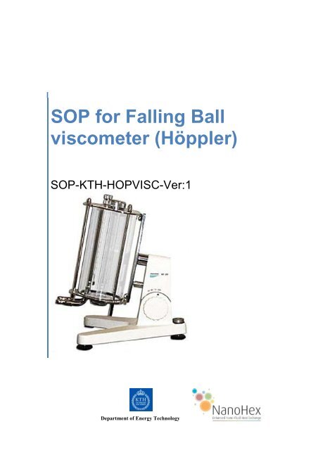
<strong>SOP</strong> <strong>for</strong> <strong>Falling</strong> <strong>Ball</strong><br />
<strong>viscometer</strong> (<strong>Höppler</strong>)<br />
<strong>SOP</strong>-KTH-HOPVISC-Ver:1<br />
Department of Energy Technology
2 <strong>SOP</strong> <strong>for</strong> <strong>Falling</strong> <strong>Ball</strong> <strong>viscometer</strong> (<br />
Reference:<br />
e.g. KTH- XYz<br />
Department of Energy Technology<br />
Measurement of viscosity of nanofluid using <strong>Höppler</strong> <strong>viscometer</strong><br />
1. Purpose<br />
1.1. Measurement of viscosity in nanofluids.<br />
2. Scope<br />
This protocol is applicable to all members of NanoHex project and provides a descriptive<br />
procedure to measure viscosity with falling-ball (<strong>Höppler</strong>) <strong>viscometer</strong> in distilled water<br />
nanofluid.<br />
3. Principle<br />
The principle of the <strong>viscometer</strong> is to determine the falling time of a ball of known diameter<br />
and density through a close to vertical glass tube of known diameter and length, filled with<br />
the fluid to be tested. The viscosity of the sample liquid is related to the time it takes <strong>for</strong> the<br />
ball to pass a distance between two specified lines on the cylindrical tube. Turning the<br />
measurement tube results in returning of the ball and it is possible to re-measure the time<br />
over the same distance. The result is dynamic viscosity with the standard dimension<br />
(mPa.s).<br />
Velocity of a ball which is falling through a liquid in a tube is dependent on the viscosity of<br />
the liquid. When the ball moves through the liquid, it is affected by the gravity, buoyancy and<br />
frictional <strong>for</strong>ces: Gravity as downward <strong>for</strong>ce, buoyancy and friction as the upward <strong>for</strong>ces<br />
(figure 1).<br />
W=mg=Vρsg=4/3πr 3 ρsg (1)<br />
ρs :density of ball<br />
g:gravitational acceleration<br />
V: volume of ball<br />
r:raduis of ball.<br />
Buoyant <strong>for</strong>ce, F1, acts upward and it is dependent of the density of the liquid which is<br />
displaced by the ball.<br />
F1=VρLg=4/3πr 3 ρLg (2)<br />
ρL=density of liquid<br />
The liquid has a dynamic viscosity, which produces a resistance against the ball movement.<br />
This frictional <strong>for</strong>ce is derived from the Stokes's law:<br />
F2=6πηru (3)<br />
u:velocity of the ball
3 <strong>SOP</strong> <strong>for</strong> <strong>Falling</strong> <strong>Ball</strong> <strong>viscometer</strong> (<br />
Department of Energy Technology<br />
Figure 1 - Body diagram of a ball in a fluid<br />
Whilst gravity and buoyant <strong>for</strong>ce are static and independent from the velocity, the frictional<br />
<strong>for</strong>ce raises with the velocity. There<strong>for</strong>e, the velocity of the falling ball raises till the net <strong>for</strong>ces<br />
is zero:<br />
W-F1-F2=0 (4)<br />
Combination of these equations would result in:<br />
u=2/9 r 2 g (ρs-ρL)/η (5)<br />
Equation (5) shows that the viscosity of liquid, η, can be gained from the velocity of ball<br />
which is going down through this liquid.<br />
The studied liquid is in a glass tube which has two marks by distance L. In the experiment,<br />
the time it takes <strong>for</strong> liquid to pass through these two marks is measured. Modification of<br />
equation (5) yields:<br />
In which the dynamic viscosity, is:<br />
Generally <strong>for</strong> simplification the constant coefficients are changed into a single coefficient, K:
4 <strong>SOP</strong> <strong>for</strong> <strong>Falling</strong> <strong>Ball</strong> <strong>viscometer</strong> (<br />
Department of Energy Technology<br />
K is <strong>viscometer</strong> constant and can be determined by using distilled water as it has well-known<br />
viscosity [3].<br />
3.1. Technical data <strong>for</strong> the equipment [1]:<br />
Measuring range: 0.6-80000 mPa.s according to DIN 53015<br />
Limit: 30-300 s<br />
Inaccuracy of measurement: 0,5-2 % according to the diameter of ball<br />
Temperature range: -60...+150 o C<br />
Measuring distance: 100mm (50mm between upper and middle<br />
lines in both directions)<br />
3.2. Equipment<br />
In measuring viscosity by <strong>Höppler</strong> <strong>viscometer</strong> one needs a stop watch and a thermometer<br />
and a water bath in order to have homogenous bath temperature besides studied solutions<br />
and distilled water <strong>for</strong> calibration. A schematic <strong>Höppler</strong> <strong>viscometer</strong> is shown in figure 2.
5 <strong>SOP</strong> <strong>for</strong> <strong>Falling</strong> <strong>Ball</strong> <strong>viscometer</strong> (<br />
Department of Energy Technology<br />
Figure 2 – <strong>Falling</strong> ball <strong>viscometer</strong> [2]<br />
1- Stand 12- Screwneck<br />
2- Viscometer 13- Sealing washer<br />
3- Spirit level 14- Bearing<br />
4- Adjusting screw 15- Nuts<br />
5- Adjustment screw 16- Upper locking plug<br />
6- <strong>Falling</strong> tube 17- Lower locking plug<br />
7- Upper plate 18- Cap<br />
8- Lower plate 19- Sealing<br />
9- Water bath jacket 20- Lid<br />
10- Olive shaped tubes 21- <strong>Falling</strong> tube screw fitting<br />
11- Fastening screw <strong>for</strong><br />
thermometer<br />
3.3. <strong>Ball</strong> selection<br />
Choice of ball is made on basis of the assumed viscosity of studied liquid and the<br />
specification which is given in table 1:<br />
<strong>Ball</strong><br />
No.<br />
Table 1- <strong>Ball</strong>s characteristics [1].<br />
3.4. Temperature control<br />
<strong>Falling</strong> ball <strong>viscometer</strong>s allow an accurate temperature control of studied liquid through the<br />
bath. The following is recommended thermostatic fluids [1]:<br />
+1...+95ºC Distilled water<br />
+80...+150ºC<br />
Glycerine mixed (pure or in appropriate ratio<br />
with water)<br />
-60...+30ºC<br />
Methyl alcohol or ethyl alcohol (pure or<br />
mixed in appropriate ratio with water)<br />
4. Safety procedures and precautions<br />
4.1. Wear rubber gloves and safety goggles during any handling of nanofluids<br />
5. Procedure<br />
Material Density<br />
ρ(gr/cm 3 )<br />
<strong>Ball</strong><br />
weight<br />
(gr)<br />
<strong>Ball</strong> constant<br />
(mPa. cm 3 /gr)<br />
Measuring<br />
range<br />
(mPa.s)<br />
1 glass 2.228 4.599 0.00891 0.6-10<br />
2 glass 2.228 4.816 0.0715 7-130<br />
3 glass 2.411 4.454 0.07755 30-700<br />
4 alloy 8.144 16.055 0.1239 200-4800<br />
5 alloy 7.909 14.536 0.6523 800-10000<br />
6 alloy 7.907 11.073 - 6000-75000<br />
5.1. Fill the falling tube with studied liquid and put in the ball cautiously. Add more liquid till<br />
no air bubbles can be seen. Then close the falling tube by its cap.
6 <strong>SOP</strong> <strong>for</strong> <strong>Falling</strong> <strong>Ball</strong> <strong>viscometer</strong> (<br />
Department of Energy Technology<br />
5.2. Be<strong>for</strong>e starting the measurement, it is better to turn the falling tube up and down at least<br />
once in order to enhance temperature uni<strong>for</strong>mity along the tube.<br />
5.3. Turn the falling tube 180 degree. Start stop watch when the ball reaches to the first<br />
marks on the tube, and measure the time between the two marks. For better and more<br />
accurate results it is recommended to repeat the measurement 10 times at each<br />
temperature.<br />
5.4. After changing the bath temperature, it’s highly recommended to wait at least 20 minutes<br />
to ensure temperature stability <strong>for</strong> the sample.<br />
5.5. At the end of the experiment, empty the tube from the liquid and remove the ball from<br />
the tube very carefully. Clean the tube with suitable solvent and/or a brush.<br />
5.6. Write down the density of liquid and ball,ρL and ρs respectively. Calculate the average t<br />
<strong>for</strong> each temperature and calculate the viscosity using equation (9).<br />
6. Calibration<br />
For calculating the <strong>viscometer</strong> constant, do all the above steps with a liquid which has a<br />
known viscosity such as distilled water but use the dynamic viscosity of distilled water in<br />
equation (9) and calculate the <strong>viscometer</strong> constant, K [2].<br />
Notes:<br />
-The liquid in the falling tube should be free of bubbles.<br />
-Generally the measurement <strong>for</strong> calibration is done at 20°C.<br />
-Measuring of the time starts when the lower edge of the ball touches the upper mark and<br />
ends when crosses the lower mark [2].<br />
7. Re-calibration<br />
7.1. As some of the nanoparticles tend to stick to the surface it is important to check the<br />
calibration of the <strong>viscometer</strong>s at regular intervals. In the initial phase of Nanohex project,<br />
the <strong>viscometer</strong>s should be checked after cleaning after each run with nanofluids. The<br />
check should be done by measuring the viscosity of distilled water at room temperature.<br />
The deviation from previously measured values must not be larger than 5%.<br />
8. References<br />
[1] - Anleitung G.,Hoppler –Viskosimeter,D.R.P.Nr.644312.<br />
[2] - Rheo Tec Messtechnik GmbH,Operating manual, <strong>Falling</strong> <strong>Ball</strong> Viscometer<br />
KF10,Germany.<br />
Available at www.rheotec.de<br />
[3] - DocStoc,2008,Using a falling-ball viscosimeter to determine the viscosity,version1.1,<br />
Available at http://www.docstoc.com/docs/28564042/Using-a-falling-ball-viscosimeter-todetermine-the-viscosity-of/


