Franz Leberl, Michael Gruber - Institut für Photogrammetrie
Franz Leberl, Michael Gruber - Institut für Photogrammetrie
Franz Leberl, Michael Gruber - Institut für Photogrammetrie

You also want an ePaper? Increase the reach of your titles
YUMPU automatically turns print PDFs into web optimized ePapers that Google loves.
'Photogrammetric Week 05' Dieter Fritsch, Ed. Wichmann Verlag, Heidelberg 2005.<br />
<strong>Leberl</strong>, <strong>Gruber</strong> 57<br />
ULTRACAM-D: Understanding some Noteworthy Capabilities 1<br />
FRANZ LEBERL 2 , MICHAEL GRUBER, Graz<br />
ABSTRACT<br />
Digital aerial photogrammetric cameras are taking over with a vengeance. While by the end of 2002, there were only 6<br />
such cameras in use globally, this increased to 16 in 2003, to 50 in 2004 and may exceed 100 in 2005. By the end of<br />
2006, more photogrammetric coverage might be produced digitally than via film. Given this rapid change in aerial<br />
imaging, what are the benefits that drive these changes? We describe in this contribution a series of noteworthy benefits<br />
that partly are applicable to all digital camera systems, and partly are specific to the Vexcel UltraCam system. They<br />
range from superior image detail via superior geometric accuracy and robustness of the image-based information, to<br />
workflow and efficiency advantages over the traditional film-based softcopy approach to photogrammetry.<br />
Key Words: Digital photogrammetry, aerial cameras, automated photogrammetry, large format framing cameras,<br />
photogrammetric workflow, pushbroom, frame imaging.<br />
1. INTRODUCTION<br />
July 2000 kicked off the race to replace the venerable aerial photogrammetric film camera by the<br />
long expected digital camera. The Amsterdam ISPRS Congress saw the announcements of the Leica<br />
ADS-40 and the Z/I-Imaging’s DMC cameras, and of the first sales of such a camera to a customer<br />
in Japan. Not surprisingly, these announcements took time to be followed up with actual routine<br />
acceptance of products, for probably 2 reasons. First was the need to mature the camera technologies<br />
in the new products, and as it turned out, this presented a multi-year effort beyond the July-<br />
2000-event. Second, and perhaps more important, was the fact that the IT-infrastructures had not<br />
evolved sufficiently, and another round of computing innovations were needed for the market to<br />
feel secure with the massive amounts of data rolling out of these new cameras. Fortunately,<br />
Moore’s law still applies, and computing advances continue to proceed at a rate of a factor of perhaps<br />
5 for each 5-year period. Naturally then the capabilities and costs for a high performance ITinfrastructure<br />
are considerably better developed by 2005 than they were by 2000. No longer is one<br />
intimidated by 1 Terabyte data sets and 100 Terabyte storage needs.<br />
However, the changes now seem to be more dynamic than previously expected. Table 1 lists the<br />
number of digital aerial cameras that have been sold each year, since 2002. We should expect that<br />
by 2006, close to 200 digital aerial cameras flying operationally. Given the capabilities and advantages<br />
of these systems, they should by then produce more images and more coverage than the sum<br />
of all remaining film cameras taken together.<br />
1<br />
This contribution is the result of an invitation by the organizers of the Photogrammetric Week, proposing a title:<br />
“UltraCam: Is there anything better?”<br />
2<br />
On leave from the <strong>Institut</strong>e for Computer Graphics and Vision, Graz University of Technology, Inffeldgasse 16,<br />
A-8010 Graz, Austria
58 <strong>Leberl</strong>, <strong>Gruber</strong><br />
What drives this rapid acceptance of the new technology? Very simply put: the digital cameras<br />
produce the familiar data at reduced cost and improved quality. Digital camera images are superior<br />
to digital film images, and they cost less. Therefore to find acceptance, the new technology does not<br />
need to create new products nor cause changes in photogrammetric procedures. Were new products<br />
and procedures needed it would require a missionary-type effort to introduce these, and this is typically<br />
a slow process. Instead, the currently established products continue to be used, but from the<br />
new digital source data, and familiar methods continue to be employed. Opportunities to enrich the<br />
range of data offerings, and to change production procedures to achieve more automation, can be<br />
interpreted as “icing on the cake”.<br />
Intergraph Vexcel Ul-<br />
Leica ADS40 DMC traCam-D Annual Accrual<br />
2000 Announced Announced 0 0<br />
2001 1 1 1<br />
2002 5 5 6<br />
2003 7 3 Announced 10 16<br />
2004 10 11 13 34 50<br />
2005 (Jan-May) 2 12 13 27 77<br />
Sum, End of May 05 25 26 26 77<br />
Table 1: Large Format Digital Aerial Cameras Sold. Sources: Written and oral pesentations at the ISPRS Workshop on<br />
“Digital Aerial Cameras”, Hannover (Germany), May 2005.<br />
However, we have been arguing that the new procedures and products should not be seen just as<br />
“icing on the cake”. Instead, they should be seen as the basis for fundamental changes of the photogrammetric<br />
value system, and we have been advocating the idea that this is resulting in a paradigm<br />
shift (<strong>Gruber</strong> et al., 2003).<br />
We will not focus on these opportunities for novel data products and procedures. Instead we will in<br />
this contribution just focus on the images produced by the UltraCam-D camera, and we want to<br />
review the effect of some of the camera specifications on the traditional photogrammetric workflow.<br />
We will document that superiority by a factor of about 2 in the edge sharpness when compared<br />
to scanned film images. We wish to point out the ability of producing very detailed urban<br />
digital elevation models from pixel data as small as 3 cm. We illustrate the improvements in matching<br />
when using digital images. We show an example of a land cover classification using high redundancy<br />
color images with an infrared channel. We present the results of some aerial triangulation<br />
projects with σ0-values at ± 1.5 μm. And we also review the effects of increasing the number of<br />
gray values in the imagery from the traditional 128 to 256 in scanned film to up to 7,000 per color<br />
channel in the UltraCam data.<br />
With an outlook towards workflow opportunities to better take advantage of the digital sensing<br />
technology, we hope to explain why the transition to digital aerial cameras has taken on a surprising<br />
dynamic that promises to create great difficulties in the market for aerial film.<br />
2. FILM VERSUS DIGITAL: SUPERIOR EDGE SHARPNESS OF DIGITAL IMAGES<br />
“Image sharpness” is usually being judged subjectively by the naked eye. However, it can also be<br />
measured and assessed quantitatively. Perko (2005) has used the edge response function to obtain<br />
edge sharpness values for scanned film imagery as well as UltraCam-D images. Generally the findings<br />
are very favorable for the digitally sensed data; Table 2 provides a summary of some of
<strong>Leberl</strong>, <strong>Gruber</strong> 59<br />
Perko’s results. Some comparisons were made with imagery flown simultaneously with a film and a<br />
digital camera, some show comparisons when the data were collected over the same terrain but at<br />
different times.<br />
In all cases investigated by Perko, the UltraCam-D images were superior in edge sharpness to the<br />
scanned film data, with the differences encompassing a factor of ~1.7. Note that in the scanned film<br />
image, an edge sharpness expressed in pixels is a function of the arbitrary selection of a scanner<br />
pixel size. To make this comparable to a digitally sourced image, one will need to compare values<br />
on the ground. Visually this quantitative advantage can be verified qualitatively, as shown in Figure<br />
1.<br />
Film System GSD Scanned Film UltraCam<br />
µ µ<br />
RMK-TOP, scanned @ 20μm 8.0 cm 1.88 1.10<br />
LMK, scanned @ 14μm 12.5 cm 2.01 1.65<br />
RC20, scanned @ 20μm 12.5 cm 1.55 1.30<br />
Table 2: Edge sharpness values present the width of an edge in pixels when considering distinct transitions from dark to<br />
bright areas. The analysis method is by Blonski et al. (2002) and is described by Perko (2005). Data provided by R.<br />
Perko.<br />
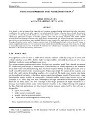
Figure 1: Scanned film (pixel size in the film is 15 μm) and UltraCam image collected over the same area at a Ground<br />
Sampling Distance GSD of 12.5 cm. Film scale 1:8000 taken with RMK TOP camera. UltraCam flying height 1400<br />
meters. Imagery acquired over 55 m by 60 m.
60 <strong>Leberl</strong>, <strong>Gruber</strong><br />
3. VERY FINE RESOLUTION IMAGING: STEREO OVERLAPS AT 3 CM PIXEL SIZE<br />
Since a digital camera image has no variable cost other than the variable cost for the (operation of<br />
an) aerial platform, one may consider larger scale imagery than that used previously. Figure 2 is an<br />
image taken at 3 cm pixel size, thus flown at an altitude of 330 meters above the ground. At such a<br />
large scale sufficient forward motion compensation (FMC) and a high frame rate is essential.<br />
Figure 2: UltraCam color image segment at 3 cm pixel size (GSD). The images were taken from a flying height of<br />
330m above the ground near Graz (Austria) at a speed over ground of 60 m/sec. The full frame covers a footprint area<br />
of 350 m by 230 m. The details are at the size of app. 6m by 5m. The FMC movement was at about 6 pixels during the<br />
exposure of 1/350 sec.<br />
Figure 3: Relationship between airplane velocity, ground sampling distance (GSD) and image repeat rate (TBFR -time<br />
between frames) at the forward overlap of 60% and 80%. The graph shows such relationship at an aircraft speed of<br />
75m/sec and 100 m/sec. The image dimension along track is assumed to be 7500 pixels.<br />
To obtain stereo overlaps at a pixel size of 3 cm requires a rapid succession of image triggers. We<br />
present in Figure 3 a relationship between aircraft velocity, pixel size and limits on overlap. At a<br />
typical velocity of 75 m per second, a 70% forward overlap with 3 cm pixels results in covering
<strong>Leberl</strong>, <strong>Gruber</strong> 61<br />
each ground point 3 times. To achieve this coverage requires an image interval of about 0.96 seconds.<br />
It is at times suggested that one can fly slowly with a slow-flying plane to achieve small pixels and<br />
maintain an overlap. But it cannot be in any one’s interest to fly slowly. Costs will be reduced by<br />
flying fast – as a result, providing a camera with a high image repeat rate makes eminent sense and<br />
supports the ability to produce stereo coverage at a high productivity at small pixel sizes.<br />
4. STEREOMATCHING: BETTER STEREO ACCURACY<br />
The digital benefit of “no-grain” combines with the digital advantage of more gray values to beat<br />
scanned film in the area of stereo matching. Figure 4 illustrates the effect on the improved density<br />
of match points when applying the same acceptance criterion for the match points. Digital source<br />
data produce more match points than scanned film. In addition, we can also study the match accuracy<br />
by a method using epipolar relationships between image pairs. Table 3 provides root mean<br />
square match errors found from scanned film and from UltraCam image pairs. The UltraCamadvantage<br />
is in the range of 1.5 to 2.<br />
Figure 4: Comparing the number of successful matches in a pair of scanned film mages and a pair of UltraCam images.<br />
The scene includes areas of poor contrast like asphalt. Left) Analog film images: 2407 points (48%) were matched.<br />
Right) Digital Camera Images: 3201 points (64%) were matched.<br />
Film Camera GSD Scanned Film UltraCam<br />
Fwhh (Pixel) Nr of Points Fwhh (Pixel)<br />
Nr of Points<br />
RMK-Top, @ 20 μm 8.0 cm 0.52 18% (1838) 0.17 73% (7292)<br />
LMK 2000, @ 14 μm 12.5 cm 0.25 35% (3466) 0.16 70% (6964)<br />
RC20, @20 μm 12.5 cm 0.31 50% (2516) 0.11 63% (3152)<br />
Table 3: Matching noise found in the data sets of Figure 4. “Noise” is found using an approach based on epipolar<br />
relationships (Perko, 2005). “Fwhh” is the “full width at half height” of the histogram of errors, and represents the σvalue.<br />
The columns with “Nr. of Points” presents the successful matches found in each image segment. In the RC20case,<br />
the areas used for the matches was parking lots and road surfaces.
62 <strong>Leberl</strong>, <strong>Gruber</strong><br />
5. CLASSIFICATION: SUPERIOR RESULTS BY MEANS OF REDUNDANCY<br />
We want to compare land use classifications using multiple UltraCam images. A simple task is to<br />
separate circulation areas (roads, parking lots) from roofs, water surfaces, vegetation (trees, shrubs)<br />
and grassy areas. Given the ability of imaging the ground at high overlaps produces multiple images<br />
for each ground point. The VRVis-team at Graz University of Technology has embarked on a research<br />
project to develop classification technology using UltraCam imagery. Of course this is to<br />
include the stereo-derived DEM and texture extracted from a panchromatic channel. However, Figure<br />
5 addresses the improvement in a classification as one goes from 1 to 2 to 3 and more overlapping<br />
images, and a visual inspection will show the classification improvements as more data get<br />
used. It is to be noted that the UltraCam produces a fresh color value in each new frame image. This<br />
represents multiple independent color observations of each object point and therefore provides a<br />
much richer input to the classification than a single color value per ground point could provide. The<br />
redundancy also affects the quality of the texture and edge values that can be introduced into the<br />
classification.<br />
Figure 5: Land use classification from multiple overlaps using color observations. The 4 independent images on the<br />
right contribute to the result on the left. Note the reduction of noise in homogeneous areas as multiple images get<br />
combined (<strong>Gruber</strong>-Geymayer, 2005). Data provided by B. <strong>Gruber</strong>-Geymayer.<br />
6. AERIAL TRIANGULATION (AT): σ0-VALUES AT ± 1μm<br />
Comparing different blocks of imagery using different ground control points is difficult. However,<br />
one number describing a photogrammetric block’s internal consistency is the σ0-value. Table 4<br />
summarizes some parameters of various UltraCam image blocks, and the associated σ0-values. Included<br />
are also some instances where the same area was covered by film imagery, flown for comparison,<br />
and variations of overlaps were used.<br />
What is relevant to note is the following:<br />
• the results appear generally very good;<br />
• in those cases where a comparison with film is feasible, the UltraCam-results are better;<br />
• systematic image errors must be modeled differently in images created by a multi-facet approach<br />
(multi-CCD, multi-lens) than in monolithic film images; σ0-values at ~ ± 1 μm are<br />
feasible if systematic errors get modeled for each CCD frame;
<strong>Leberl</strong>, <strong>Gruber</strong> 63<br />
• the option of flying with more than 60% forward overlap should be used since it does improve<br />
the accuracy, the block is more stable and as one deals with multi-ray intersections,<br />
the accuracy on the ground is favorably affected;<br />
• it is important that the costs of the aerial triangulation be as fixed as possible, and as little<br />
variable as possible; if one succeeds, one renders irrelevant the number of image files to be<br />
processed through an AT.<br />
Table 4: Aerial triangulation results with UltraCam image blocks and analog film images (by Dr. Richard Ladstätter,<br />
<strong>Institut</strong>e for Remote Sensing and Photogrammetry,Technical University Graz). Both, the analog film camera at a focal<br />
length of 21 cm and UltraCamD have been operated simultaneously in a twin hole aircraft. The flight missions were<br />
performed by the Federal Office of Surveying and Mapping (BEV), Vienna, Austria.<br />
7. MORE THAN 8 BIT IMAGING: FREEDOM FROM LIGHTING CONSTRAINTS<br />
The increase of the radiometric range to 12 bits or more, obtained via a 72 db signal-to-noise ratio<br />
of the CCDs, combined with a 14 bit analog-to-digital conversion, is yet to really enter fully into the<br />
photogrammetric psyche. Figure 6 presents a sample image in 8 bit format for presentation on paper,<br />
and Figure 7 has the associated histograms, showing that up to 6000 gray values exist in the<br />
various channels of one image. The very bright areas are small and therefore the histogram does not<br />
contain many samples. However, it is the very bright areas in which we want to see details, while<br />
also presenting shadow details. In Figure 6 and 7 we have attached local transformations for each<br />
area into 8-bits.<br />
The technologies to take the 4,000 to 6,000 or more gray values and compress them intelligently<br />
into 256 values are yet to be fully developed. It is non-trivial to “throw away” 94% of the information<br />
in an intelligent fashion and find the 6 % of greatest relevance. The goal has to be to optionally<br />
fly under low light conditions and yet to obtain quality imagery, as well as presenting the images to<br />
the eye in display media (monitors, paper, film) in an optimum fashion in which the relevant information<br />
is preserved. Traditional film thinking is of very limited use in this context. Highly nonlinear<br />
transformations from the 12 - 14 bit formats into the resulting 8 bits are needed, and must be<br />
obtained from experimental and theoretical considerations. We are concerned with this issue and
64 <strong>Leberl</strong>, <strong>Gruber</strong><br />
currently in the process of developing the relevant technologies to be available in the upcoming<br />
versions of the UltraCam post-processing software.<br />
Figure 6: Sample UltraCam-D image with very bright, dark and very dark areas, presented on paper with 8 bits. The<br />
segments are optimized for the local contrast. Bright snow, dark shadows and even the very dark forest area show a<br />
variety of fine details. The image was taken on March 1 st 2005 at a GSD of 25 cm. Sample areas cover a footprint of<br />
appr. 50 m by 50 m (200 pixels by 200 pixels).<br />
Figure 7: Histograms of the sample image in Figure 6 show more than 6,000 digital numbers (DN). The comparison of<br />
16 bit (upper row) and 8 bit (lower row) histograms clearly show that each of the three test areas contain more than 256<br />
intensity levels (the maximum at 8 bit). The transition to 8 bit obviously causes a loss of radiometric image information.<br />
8. RADIOMETRIC MODELING: 5 BAND IMAGING AND INFRARED<br />
The UltraCam produces for each collected image an independent set of 5 spectral bands: pan, blue,<br />
green, red and near-infrared. As an object moves through the camera’s field-of-view, it gets repeatedly<br />
imaged and a set of new spectral observations gets collected. For automated procedures, this<br />
input is often usable in its “raw” form, and we have addressed this in the Item 5 on Classification.<br />
For visualization, it is necessary to create 3-band output from the 5-band input.
<strong>Leberl</strong>, <strong>Gruber</strong> 65<br />
The technologies for visualizing multi-spectral data are well developed due to the decennia of history<br />
in satellite remote sensing. The UltraCam produces the pan-channel at a geometric resolution<br />
exactly 3 times greater than the resolution of the color bands. The visualization therefore employs a<br />
process of “pan-sharpening” at the ratio 1:3, to take the best from each channel.<br />
9. WORK FLOW CONSIDERATIONS: WEB-ENABLED IMAGE SERVER<br />
The transition from film to digital does away with the roll of film as the permanent storage and archiving<br />
device. Scans made from film images did not have great “value” because they could always<br />
be recreated from the film source.<br />
The totally digital workflow changes this and a new issue presents itself – dealing with digital data<br />
as the only format, and protecting these data therefore against loss and damage. A new requirement<br />
has therefore been evolving in the form of a “Server”. Figure 8 shows the UltraMap Server with a<br />
tape robot, in this particular case for 200,000 uncompressed images available near line via the<br />
Internet or an Intranet. Included are RAID disks and multiple CPUs, plus considerable software for<br />
cataloging, archiving, project management and processing of UltraCam images.<br />
Figure 8: The UltraMap Server satisfies the new need for managing, processing, cataloging, archiving and protecting<br />
digital image harvests from the UltraCam-D. An unlimited number of images can be managed in such a tape archive. A<br />
subset of perhaps a few 100,000 is kept near-line, and current images are online. Access is via a web browser.<br />
10. TECHNOLOGY ISSUES: PUSHBROOMING VERSUS FRAMING CAMERAS<br />
Two Competing Technologies<br />
Considerable interest exists in the photogrammetric community to compare the two major competing<br />
technologies for digital image collection:<br />
• the push-brooming approach using multiple linear arrays, one for each color band and lookdirection,<br />
creating geometric rigor via measurements of the sensor position and attitude;<br />
• the frame camera approach in analogy to photogrammetric film cameras, with an internal<br />
geometric rigor associated with each collected image by virtue of the camera design.
66 <strong>Leberl</strong>, <strong>Gruber</strong><br />
Obviously, we are believers in (1) the validity of the photogrammetric image, (2) the use of the legacy<br />
of photogrammetric knowledge and procedures, (3) the ability to serve at any desired photogrammetric<br />
scale and (4) in the value of redundant observations. Framing cameras do serve these<br />
interests very well, pushbroom-cameras do not. Therefore we built the UltraCam.<br />
Pansharpening<br />
This is an issue associated with the technology discussion. At a resolution ratio 1:3 between pan and<br />
color bands, we obtain pansharpened color images that have thus far not shown any compromises in<br />
any photogrammetric or even remote sensing applications (See also Perko, 2005). The color bands<br />
have high radiometric performance since they are collected with sufficient integration time (the<br />
proper exposure time for the amount of available light), and each image obtains its own individual<br />
color information. In contrast, pushbrooming-color is obtained at comparatively short exposure<br />
times to match the high resolution of the pan channel. There exists the option to pushbroom in color<br />
with longer exposure periods, but this produces larger pixels, the resolution of the color bands is<br />
reduced and pansharpening is needed also in the pushbrooming case to produce color images.<br />
Square versus Rectangular Format<br />
Digital framing cameras do employ a rectangular format. The base-to-height ratio of an image pair<br />
at 60% forward overlap is better for a square format than the rectangular format. Users view this<br />
with some concern. Technologically this concern is not justified. It is to be noted that at a forward<br />
overlap of 80%, image 1 combined with image 5 produces a base-to-height ratio superior to that<br />
achieved with 60% overlap and a square format. Numerical stereo, for example for the creation of<br />
DEMs, will benefit from the intersection geometry of non-adjacent images.<br />
In addition we find that the digital data’s stereo matching quality is sufficiently superior to scanned<br />
film so that this alone compensates the geometry restriction.<br />
Large Format versus Middle Format Imaging<br />
Occasionally one hears ideas that large format cameras are not needed and middle format cameras<br />
can replace them. The fixed costs of photogrammetric surveys would be affected favorably since<br />
middle format cameras are less expensive than large format systems. The variable costs would be<br />
affected unfavorably, since data collection would need a much greater effort. Also compromised<br />
would be the geometric performance since the stereo overlaps would be comparatively poor. We do<br />
not believe that large format cameras will be done away by future middle format systems.<br />
And in terms of overall data quantities and data flow, this is defined by the terrain area to be imaged<br />
and the desired overlaps, not by the sensor producing the data. This consideration alone illustrates<br />
how inefficient smaller format cameras really are.<br />
Color by Bayer Pattern versus Independent Observation of each Color Band<br />
Middle format cameras typically use a single CCD area array and obtain color by the Bayer pattern<br />
approach (see <strong>Leberl</strong> et al., 2002). To produce a color image one needs to perform a color interpolation<br />
that is denoted as “demosaicking” and may be considered a process similar to “pansharpening”.<br />
Color quality may not approach that of the separate measurement of color by individual<br />
CCD/lens/filter combinations. The high radiometric range of the panchromatic channel is entirely<br />
absent.<br />
Technology Evolution<br />
Recent public tenders for digital cameras have included the question for the technology and product<br />
evolution in the coming years. They are characterized by the following issues:
<strong>Leberl</strong>, <strong>Gruber</strong> 67<br />
• Moore’s law continues to remain in effect, and therefore all things “computing” will evolve<br />
rapidly to more disk space, more tape capacity, more computing capability, more speed,<br />
more internet transfer etc.<br />
• CCD technology is not evolving as rapidly as the computing domain, since the much smaller<br />
market cannot support the massive research applied to computing;<br />
• The ultimate limitation for camera performance exists in the area of optics.<br />
We cannot publish Vexcel’s technology plans. However, from the above factors one can deduce<br />
that the big innovation step was to get to today’s camera systems. Improving camera system specifications<br />
relevant to photogrammetric applications will probably not evolve dramatically over the<br />
years.<br />
Photogrammetry Evolution<br />
Photogrammetry is increasingly software-only, and the innovations that are now possible thanks to<br />
no-variable-cost imagery need to start coming to fruition. The visions of AT-, DEM- and orthophoto<br />
robots, and associated automated tools to populate 3D GIS data bases, need to be realized.<br />
Once this becomes reality, photogrammetry will be totally changed.<br />
11. CONCLUSIONS<br />
We attempted to review the reasons why digital aerial cameras have developed such an amazing<br />
market dynamic that very soon the majority of aerial photogrammetric imagery will be digital and<br />
no longer produced via film. The presented evidence should make it easy to support this conclusion.<br />
A discussion of the technology, its evolution and of the entire workflow into which the digital camera<br />
is embedded was not the focus of this contribution. We do address some issues of technology<br />
evolution, but leave a deeper discussion for another opportunity.<br />
ACKNOWLEDGEMENT<br />
We wish to thank Dr. Barbara <strong>Gruber</strong>-Geymayer, Dr. Richard Ladstätter and Dr. Roland Perko for<br />
help they provided with some of the illustrations.
68 <strong>Leberl</strong>, <strong>Gruber</strong><br />
REFERENCES<br />
Blonski, S., Pagnutti, M., Ryan, R. E. and Zanoni, V. (2002) In-flight edge response measurements<br />
for high spatial-resolution remote sensing systems. In: W. L. Barnes (ed.), Proceedings of the<br />
SPIE: Earth Observing Systems VII, Vol. 4814, pp. 317–326.<br />
<strong>Gruber</strong>-Geymayer B.C., A. Klaus A., K. Karner K.(2005) Data Fusion for classification and object<br />
extraction, To appear in Proceedings of Joint Workshop of ISPRS and the German Association<br />
for Pattern Recognition 'Object Extraction for 3D City Models, Road Databases and Traffic<br />
Monitoring -Vienna,Austria, 29-30 August 2005.<br />
<strong>Gruber</strong> M., <strong>Franz</strong> <strong>Leberl</strong>, Roland Perko (2003) Paradigmenwechsel in der <strong>Photogrammetrie</strong> durch<br />
Digitale Luftbildaufnahme? <strong>Photogrammetrie</strong>, Fernerkundung, Geoinformation.<br />
<strong>Leberl</strong> F., R. Perko, M. <strong>Gruber</strong> (2002) Color in Photogrammetric Remote Sensing. Proceedings of<br />
the ISPRS Commission VII Symposium, Hyderabad, India. ISPRS Archives, Volume 34, Part<br />
7. Available from GITC bv, Lemmer The Netherlands, pp. 59-64<br />
<strong>Leberl</strong> F., M. <strong>Gruber</strong>, M. Ponticelli, S. Bernoegger, R. Perko (2003) The Ultracam Large Format<br />
Aerial Digital Camera System. Proceedings of the ASPRS Annual Convention, Anchorage<br />
USA, 5-9 May.<br />
Perko R. (2005) Image Quality: Digital Pansharpening Versus Full Color Film. Manuscript submitted<br />
for publication. Check also www.vexcel.com.