Chi-Ming Lee Chief of Combustion Branch NASA Glenn Research ...
Chi-Ming Lee Chief of Combustion Branch NASA Glenn Research ...
Chi-Ming Lee Chief of Combustion Branch NASA Glenn Research ...

You also want an ePaper? Increase the reach of your titles
YUMPU automatically turns print PDFs into web optimized ePapers that Google loves.
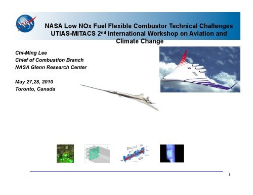
<strong>Chi</strong>-<strong>Ming</strong> <strong>Lee</strong><br />
<strong>Chi</strong>ef <strong>of</strong> <strong>Combustion</strong> <strong>Branch</strong><br />
<strong>NASA</strong> <strong>Glenn</strong> <strong>Research</strong> Center<br />
May 27,28, 2010<br />
Toronto, Canada<br />
1
ERA/SFW System Level Metrics<br />
…. technology for improving noise, emissions, & performance<br />
CORNERS OF THE<br />
TRADE SPACE<br />
Noise<br />
(cum below Stage 4)<br />
LTO NOx Emissions<br />
(below CAEP 6)<br />
Performance:<br />
Aircraft Fuel Burn<br />
Performance:<br />
Field Length<br />
N+1 (2015)***<br />
Generation<br />
Conventional Configurations<br />
relative to 1998 reference<br />
N+2 (2020)***<br />
Generation<br />
Unconventional Configurations<br />
relative to 1998 reference<br />
N+3 (2025)***<br />
Generation<br />
Advanced Aircraft Concepts<br />
relative to user-defined reference<br />
-32 dB -42 dB -71dB<br />
-60% -75% better than -75%<br />
-33%** -40%** better than -70%<br />
-33% -50% exploit metro-plex* concepts<br />
***Technology Readiness Level for key technologies = 4-6<br />
** Additional gains may be possible through operational improvements<br />
* Concepts that enable optimal use <strong>of</strong> runways at multiple airports within the metropolitan area<br />
Approach<br />
- Enable Major Changes in Engine Cycle/Airframe Configurations<br />
- Reduce Uncertainty in Multi-Disciplinary Design and Analysis Tools & Processes<br />
- Develop/Test/ Analyze Advanced Multi-Discipline Based Concepts & Technologies<br />
2
NOx emissions vs. the Overall Pressure Ra5o and SFC<br />
3
LTO (landing and take-<strong>of</strong>f) NOx Regulations Relative<br />
to CAEP 6 ( @ 30 OPR for Engines >89.0 KN <strong>of</strong> Thrust)<br />
120%<br />
100%<br />
80%<br />
60%<br />
40%<br />
20%<br />
CAEP6 ICAO NOx Regulations for Engines<br />
B777/GE90<br />
N+1, FAA CLEEN<br />
CAEP 6<br />
0%<br />
1986 1990 1994 1998 2002 2006 2010 2014 2018 2022<br />
Year<br />
GEnx -1B 55% below CAEP 6<br />
RR Trent 1000 ~50% below<br />
CAEP 6 (Predicted)<br />
PW 810 ~50% below CAEP 6<br />
(Estimated)<br />
N+2 Goal<br />
-75%<br />
4
Flametube<br />
Combustor<br />
Emissions Reduction - Technology to Product Transition<br />
<strong>NASA</strong> Program<br />
Sector<br />
Combustor<br />
<strong>NASA</strong> Project will develop and<br />
demonstrate low emissions to a<br />
technology readiness level (TRL) 6<br />
Full Annular<br />
Combustor<br />
Engine<br />
Integration<br />
TRL- 3 TRL- 4 TRL- 5 TRL- 6<br />
Industry Product Integration<br />
Market conditions and available technology<br />
improvements determine opportunity to<br />
launch new product engine<br />
“Off-Ramp” for Technology<br />
Industry:<br />
• Scaling to product engine size<br />
• Production engine design<br />
• Durability testing<br />
• Transient testing (altitude/flying test-bed)<br />
• Inclement weather testing<br />
• Manufacturing processes and tooling<br />
• Certification<br />
• Product support<br />
Certification and Entry Into Service<br />
TRL-9<br />
<strong>NASA</strong> and Industry Partnership for Low-Emission Combustor Technology Development !<br />
Followed by Possible Industry Certification and Product Implementation!<br />
5
Active<br />
<strong>Combustion</strong><br />
Control<br />
Methods<br />
Fuel<br />
Fuel Actuators<br />
Synergistic Technologies to Enable<br />
Ultra-Low Emissions <strong>Combustion</strong><br />
Feedback<br />
Sensors<br />
Manufacturing<br />
Processes<br />
Ultra-Low<br />
Emissions<br />
<strong>Combustion</strong><br />
Combustor<br />
and<br />
Fuel System<br />
Dynamics<br />
Materials<br />
Facilities for<br />
Realistic<br />
Test Conditions<br />
Fuel Injection<br />
Dynamics<br />
and<br />
Flameholding<br />
6
Fuel Flexible/Low Emissions<br />
Combustor Technical Challenges<br />
• Injector/Mixer Design<br />
• Active <strong>Combustion</strong> Control<br />
• High Temperature <strong>Combustion</strong> Liner<br />
Fuel<br />
Staging<br />
CMC<br />
Liners<br />
Instability<br />
Control<br />
7
Injector/Mixer Design Challenge<br />
8
75% Nox Reduction Injector Development<br />
• Advanced Injector Concept<br />
• Fuel/Air Mixing<br />
• Ignition<br />
9
Fischer-Tropsch & Jet A Fuel Analysis<br />
Test F-T Jet A<br />
Total Acid Number (mg KOH/g) 0.002 0.00<br />
Aromatics (% vol) 0.0 19<br />
Mercaptan Sulfur (% mass) 0.000 0.000<br />
Total Sulfur (% mass) 0.00 0.0<br />
Distillation<br />
Initial Boiling Point (°C) 149<br />
10% Recovered (°C) 162 180<br />
20% Recovered (°C) 163<br />
50% Recovered (°C) 168 212<br />
90% Recovered (°C) 184 251<br />
End Point (°C) 196<br />
Residue (% vol) 0.9 1.3<br />
Loss (% vol) 0.4 0.9<br />
Flash Point (°C) 44 51<br />
API Gravity @ 60°F 60.5<br />
Freezing Point (°C) -55 -48<br />
Viscosity @ -20°C (mm²/s) 2.6 5.2<br />
Net Heat <strong>of</strong> <strong>Combustion</strong> (MJ/kg) 44.2<br />
Test F-T Jet A<br />
Hydrogen Content (% mass) 15.6<br />
Smoke Point (mm) 40.0 21<br />
Copper Strip Corrosion (2 h @<br />
100°C)<br />
1a<br />
Thermal Stability @ 260°C<br />
Change in Pressure (mmHg)<br />
Tube Deposit Rating, Visual<br />
Existent Gum (mg/100 mL)
Time--><br />
C 8<br />
C 9<br />
C 10<br />
C 11<br />
F-T Fuel Analysis<br />
C 12<br />
5 10 15 20 25 30<br />
C 13<br />
C 14<br />
C 15<br />
5172 F-T Kerosene<br />
C 16<br />
Syntroleum<br />
4909 S-8<br />
C 17<br />
C 18<br />
C 19<br />
11
Concentration<br />
0<br />
Time--><br />
C 7<br />
C 8<br />
Fischer-Tropsch & JP-8 Fuel Analysis<br />
C 8<br />
C 9<br />
C 10<br />
C 11<br />
C 12<br />
C 13<br />
C 14<br />
C 15<br />
C 16<br />
C 17<br />
5 10 15 20 25 30<br />
Time<br />
C 18<br />
Shell<br />
F-T<br />
JP-8<br />
C 19<br />
12
JP8, 50-50 Blend, and FT-2 Comparisons<br />
Video Images, with flow from left to<br />
right<br />
Comparison showing average flame length and luminous intensity for T3 = 1030°F<br />
13
Advanced Subsonic Combustor Rig (ASCR)<br />
Alternative Fuels Establishment (cont’d)<br />
14
ASCR Plenum Design and Fabrication (cont’d)<br />
15
Active <strong>Combustion</strong> Control Challenge<br />
16
Ultra-Lean-Burning Combustors<br />
Are More Susceptible to Thermo-Acoustic Instabilities<br />
1. Higher-performance<br />
fuel injectors: more<br />
turbulence<br />
3. More uniform temperature and<br />
composition<br />
5. Experience in ground-power gas-turbines<br />
2. Reduced film cooling: reduced<br />
damping<br />
4. No dilution holes: reduced<br />
flame-holding<br />
17
<strong>Combustion</strong> Instability Control Strategy<br />
Objective: Suppress combustion thermo-acoustic instabilities when they<br />
occur<br />
Φ’<br />
+<br />
+ Fuel-air<br />
Mixture system<br />
<strong>Combustion</strong><br />
Process<br />
Actuator<br />
Closed-Loop Self-Excited System<br />
Controller<br />
Combustor<br />
Acoustics<br />
Natural feed-back process<br />
Artificial control process<br />
Sensor<br />
P’<br />
18
Long Term Goal for Active <strong>Combustion</strong> Control<br />
• Improve fundamental understanding <strong>of</strong> the<br />
combustor processes<br />
in order to…<br />
• More effectively integrate multi-point combustor<br />
design, controls, sensor, and actuator technologies<br />
to provide…<br />
– An intelligent fuel/air management system with<br />
temporal and spatial fuel modulation for<br />
• Instability avoidance/suppression<br />
– Thermoacoustics, blowout<br />
• Pattern factor control<br />
• Emissions minimization<br />
to enable…<br />
� Combustors with extremely low emissions<br />
throughout the engine operating envelope<br />
19
Active <strong>Combustion</strong> Control<br />
… In order to achieve 75% NOx reduction, it is necessary<br />
to demonstrate the capability to detect and suppress<br />
combustor instabilities for these very low emission<br />
combustors in order to enable efficient combustor<br />
operation at all conditions.<br />
• Develop sensor, actuation, high temperature electrical components for<br />
processing control signals, and control methodologies for integrated<br />
demonstration with the low emissions concepts<br />
• Utilize the flametube and sector combustor test capability<br />
� Goal - Keep pressure oscillation to within 1% <strong>of</strong> nominal at all<br />
power conditions in a sector rig indicative <strong>of</strong> a 75% NOx reduction<br />
combustor (TRL 5).<br />
20
Active <strong>Combustion</strong> Control<br />
<strong>Combustion</strong> Instability Dynamics Simulation <strong>of</strong> an advanced, low-emissions combustor prototype<br />
2 dynamic pressure transducers,<br />
P 31,& P 32<br />
2 1-element traversing<br />
probes<br />
dynamic pressure transducer,<br />
P 4DynUp, semi-infinite coil<br />
5-element probe<br />
CE5B-STAND 1 TEST RIG SCHEMATIC<br />
dynamic pressure transducer,<br />
P 4DynDn, semi-infinite coil<br />
Simulation Features<br />
• Physics-based, Sectored<br />
1-D, reacting<br />
• Time-accurate<br />
• Computationally efficient<br />
area transitions<br />
• Upstream and<br />
Downstream boundary<br />
conditions modeled to<br />
match rig<br />
CE5B-STAND 1 SIMULATION LAYOUT<br />
21
SiC Pressure Sensor Status<br />
• The design, fabrication, and testing <strong>of</strong> a SiC dynamic pressure sensor is ongoing. These activities<br />
include both extending the sensor material structure to higher temperatures as well as characterizing<br />
the present pressure sensor structure.<br />
• The work includes sensor fabrication (<strong>NASA</strong> GRC Microsystems Fabrication Clean Room) and<br />
packaging <strong>of</strong> pressure sensor (Sienna Technologies, Inc.)<br />
• Collaborating with Sienna Technologies, Inc. to develop a high temperature sealing glass with high<br />
glass transformation temperature to support pressure sensor operation at 800 o C. A new glass mix<br />
was applied on a dummy SiC chip and an old AlN header and both passed the hermiticity and<br />
adhesion tests (Figure 1).<br />
• Packaging <strong>of</strong> several sensors with the modified MEMS-DCA package capable <strong>of</strong> operating at 800 o C<br />
(Figure 2) is underway. These sensors were fabricated with a high temperature metallization<br />
approach which is a modified version <strong>of</strong> the existing metallization scheme (Ti/TaSi 2 /Pt). The result is<br />
a baseline for subsequent tests with sensors fabricated with a next generation metallization scheme.<br />
• Meetings have been held related to testing in the research combustor in CE-5. Required pressure<br />
fittings have been ordered and, when they arrive, a temperature gradient test will be conducted to<br />
determine how long <strong>of</strong> a sensor will be needed for the combustor testing. This information will be fed<br />
to Sienna Technologies for sensor construction.<br />
Figure 1 Newly developed 800 o C sealing glass demonstrated on a<br />
dummy sensor and AlN package header.<br />
Figure 2: Modified MEMS-DCA package to support<br />
800˚C pressure sensor operation.<br />
22
SiC Electronics Status<br />
• Building on world-record long-term operation <strong>of</strong> high temperature SiC electronics circuits<br />
(e.g., the differential amplifier in Figs. 1 and 2), we will be fabricating the next generation <strong>of</strong><br />
SiC electronics with increased complexity and transistor count.<br />
• In-package integration <strong>of</strong> SiC electronics with pressure sensors allows processing <strong>of</strong> sensor<br />
signals in-situ, improving the accuracy and reliability <strong>of</strong> the data in harsh environments.<br />
• Test structures are being fabricated in the <strong>NASA</strong> GRC Microsystems Fabrication Laboratory<br />
to verify the newly developed multilevel interconnect process, which will be used to<br />
configure tens <strong>of</strong> SiC transistors in integrated circuits.<br />
• A prototype 500 °C SiC integrated circuit amplifier and analog-to-digital (A/D) converter for<br />
use with an SiC dynamic pressure sensor has been designed. Fig. 3 shows the amplifier<br />
design. Fabrication <strong>of</strong> wafers with these electronics will begin in 1 month and should be<br />
completed 10 months later, after which the circuits will be packaged and tested.<br />
30µm<br />
Fig. 1. Differential amplifier circuit<br />
using two SiC transistors.<br />
Fig. 2. Diff amp test waveforms<br />
showing
Active <strong>Combustion</strong> Instability Control Via Fuel Modulation<br />
High-temperature sensors<br />
and electronics<br />
High-frequency fuel delivery<br />
system and models<br />
Physics-based instability models<br />
Emissions Probe<br />
Fuel<br />
Valve<br />
Advanced control methods<br />
+<br />
Pressure from +<br />
Fuel lines, Injector Fuel Modulation + Combustor Pressure<br />
Flame<br />
& <strong>Combustion</strong><br />
Phase Shift<br />
Controller<br />
White Noise<br />
Filter<br />
Combustor Instrumentation<br />
(pressures, temp’s)<br />
Fuel Injector<br />
Acoustics<br />
Realistic combustors, rigs for research<br />
NL<br />
Instability Pressure<br />
24
SiC Pressure Sensor Status<br />
• The design, fabrication, and testing <strong>of</strong> a SiC dynamic pressure sensor is ongoing.<br />
These activities include both extending the sensor material structure to higher<br />
temperatures as well as characterizing the present pressure sensor structure.<br />
• A landmark attempt was made to test the SiC pressure sensor with newly<br />
developed higher temperature (> 600 °C) packaging materials. The sensor was<br />
pressurized and measurement taken at various temperatures up to 750 C.<br />
• Pressure measurement at 750 °C indicated a net output <strong>of</strong> approximately 7 mV fullscale<br />
at 500 psi. While the observed instability in the device prevented further<br />
testing, the result validates the concept <strong>of</strong> using piezoresistive based SiC pressure<br />
sensors for measurement in 750 °C environment.<br />
25
SiC Electronics Status 03/22/2010<br />
• A wafer <strong>of</strong> multilevel interconnect test structures is approximately 50% completed and should be finished<br />
in about 6 weeks. These test structures will verify the newly developed multilevel interconnect process<br />
which will be used to configure tens <strong>of</strong> SiC transistors in integrated circuits for use at temperatures to 500<br />
°C. Figure 1 shows probe testing <strong>of</strong> 8-µm-wide vias through the overlying dielectric layer to the SiC<br />
substrate <strong>of</strong> the test wafer. A 4-µm via, at right, is too small to probe test. A via size <strong>of</strong> 4 µm will enable a<br />
transistor gate width <strong>of</strong> 2 µm for high density integrated circuits. Fabrication <strong>of</strong> such small features is<br />
technically challenging in a class 100 research cleanroom such as ours, yet is important to enable the<br />
fabrication <strong>of</strong> more complex integrated circuits with greater functionality. So far, we have achieved good<br />
results with the smallest size test structures.<br />
• Masks for a SiC integrated circuits have been designed. Fabrication <strong>of</strong> these circuits will begin after the<br />
multilevel interconnect test structures successfully pass operational verification testing on a probe station.<br />
These circuits should be completed by the end <strong>of</strong> January, 2011. Circuits to be fabricated include a 500 °C<br />
SiC integrated circuit amplifier (shown in Fig. 2) for use with an SiC dynamic pressure sensor.<br />
Fig. 1 - Probe testing <strong>of</strong> 8-µm-wide vias through dielectric layer<br />
<strong>of</strong> interconnect test structure wafer. A 4-µm via is visible at right.<br />
Fig. 2 - Design <strong>of</strong> SiC amplifier for<br />
dynamic pressure sensor.<br />
26
High Temperature Combustor Liner Challenge<br />
Objectives: Investigate CMC combustor liner materials, identify issues<br />
challenging CMC incorporation into engines, mitigate issues as possible<br />
Issues for CMC Liner –<br />
Durability –<br />
Insufficient data – both long term coupon and<br />
relevant engine environment<br />
Mitigation – In-house durability testing,<br />
coupon creep/fatigue/etc testing, HPBR,<br />
Subcomponent (NRA) testing.<br />
Advanced Coatings – improved coating compositions,<br />
erosion, spallation, repairability<br />
Mitigation - In-house research effort on advanced coatings, HPBR investigations, insufficient funds for repairability<br />
Integration – Attachment design & fretting coatings<br />
Mitigation - NRA for attachment design (?), in-house investigation in fretting coatings, coeff friction, various materials etc<br />
27
ERA CMC LINER -Overview<br />
Objectives: Investigate CMC combustor liner materials, identify issues<br />
challenging CMC incorporation into engines, mitigate issues as possible<br />
Approach:<br />
• Investigate basic properties <strong>of</strong> relevant CMC<br />
• Develop high coatings<br />
• NRA to obtain subcomponents<br />
• Collaborate extensively with Engine companies<br />
• Test subcomponents in (hot) engine vibratory environment<br />
18.5”<br />
GE 7FA<br />
Benefits:<br />
CMC combustor liner enables new engine designs incorporating higher<br />
engine temperatures and reduced cooling air flows<br />
Status:<br />
42”<br />
• Issues with CMC combustor liner identified with Engine company input<br />
• Basically on schedule – NRA may result in delays<br />
• Task planned, budget allocated<br />
• Selected baseline material<br />
HiPerComp Type 2 – procurement<br />
• Plans for Subcomponent delivery via NRA<br />
• Coating systems selected, procurements underway<br />
• Test matrices developed for coupon testing w&w/o coatings<br />
28<br />
14”
ERA CMC LINER – Subtasks<br />
1. Liner material testing<br />
Issues –<br />
Durability insufficiently understood<br />
or proven<br />
Status –<br />
Coupon panels in procurement<br />
Testing procurements underway<br />
Changes to HPBR underway for hot cooling air<br />
2. Advanced Coating Development<br />
Issues –<br />
Temps pushed to 2800F – better coatings needed<br />
<strong>NASA</strong> coatings compared to GE coating<br />
Repair coatings?<br />
Status-<br />
on track, procurements underway<br />
3. CMC Engine Integration Issues<br />
3a –CMC Attachments<br />
Issues –<br />
CMC attachment design<br />
metal wear /vibratory environment<br />
chemical issues at high temp?<br />
Status -<br />
on track – insufficient bodies?<br />
NRA impact uncertain<br />
3b – Joining<br />
Issues –<br />
thermal expansion mismatch<br />
chemical interaction?<br />
Status – slow start<br />
4. Fuel modulation<br />
Issues –Higher temp piezos –<br />
from 250F to 400F<br />
Status –<br />
on track<br />
procurements finished by April 30<br />
29
ERA CMC Liner<br />
Material Testing<br />
Objectives:<br />
Investigate durability issues for GE HiPerComp Type 2 CMC for high<br />
temperature engine environments.<br />
Approach:<br />
Investigate basic durability properties <strong>of</strong> coupons – 2D uni-layup prepreg Hi-<br />
Nic-S, balanced (yr 1).<br />
Develop advanced high temperature<br />
coatings<br />
NRA to obtain subcomponents<br />
Collaborate closely with Engine companies<br />
Test subcomponents in simulated engine<br />
environment<br />
Benefits:<br />
CMC combustor liner enables higher temp engine, liner surface operating<br />
temperature to 2800F<br />
Status:<br />
• Prepreg SiC CMC panels ordered.<br />
• HPBR modifications underway<br />
• Subcomponents obtained by NRA<br />
30
ERA CMC Liner<br />
Material Testing- Environmental Barrier Coatings<br />
Objective-<br />
Develop and validate advanced 2800°F<br />
environmental barrier coating (EBC) systems<br />
for SiC/SiC CMC combustors for ERA engine<br />
demonstrations.<br />
Status -<br />
• GE contract plan discussed for combustor EBC testing and development<br />
• Quote received from Sulzer for first round <strong>of</strong> environmental barrier coating<br />
powders<br />
• Collaborative plan for Dense-Vertical Cracked (DVC) combustor EBC<br />
development also discussed with Praxair<br />
• Potential trial non-Si bond coats development<br />
• High Pressure Burner Rig fixtures designed and fabricated for thermal<br />
fatigue and environmental degradation tests <strong>of</strong> impingement and filmcooled<br />
CMC-EBC test coupons<br />
• High Pressure Burner Rig Combustor being instrumented for CMC<br />
combustor segment rig fixture designs and testing<br />
• High pressure burner rig cooling air capability improved (up 600 psi) and<br />
fuel is being improved to accommodate planned higher mass-flow rate tests<br />
• Simulated thermal gradient fatigue laser rig also ready for 2 inch diameter<br />
CMC-EBC specimen thermal fatigue testing<br />
• Biaxial stress <strong>of</strong> heated CMC ring-on-ring test analyzed<br />
31
Objectives:<br />
ERA CMC Liner<br />
Integration Technology - Attachments<br />
Investigate fretting/wear/erosion issues<br />
involved with integrating CMCs into<br />
high temperature, dynamic engine<br />
environments. High temperature fretting<br />
coatings development required to<br />
protect metal components<br />
Approach:<br />
• Investigate basic properties <strong>of</strong> relevant<br />
materials<br />
• Develop high temperature fretting<br />
coatings<br />
• NRA to obtain subcomponents<br />
• Collaborate with Engine companies<br />
• Test subcomponents in (hot) engine<br />
vibratory environment<br />
Benefits:<br />
Enable integrating <strong>of</strong> critical CMC<br />
components<br />
Status:<br />
• Planning meetings with RXC/RXN/GE to<br />
identify R&D efforts is on-going.<br />
Collaborating with GE to develop<br />
needed data.<br />
• Rehabbing a high temperature fretting<br />
rig to evaluate samples at up to 1832 F.<br />
• Fretting coatings systems identified<br />
CMC-Metal oxidation-wear coatings: nitriding surfaces, nitride coatings<br />
(TiAlCrTaSiN among others) compared to superalloy substrates<br />
• HVOF nitride-bond coat cermet coatings may also be explored<br />
32
High Temperature Piezoelectric Material (GRC)<br />
� Improved operating temperature<br />
� Improved coercive field<br />
� Improved remenant polarization<br />
ERA – CMC Liner - Alp Sehirlioglu<br />
Fuel Modulation with HT Piezos<br />
High Temperature<br />
Piezoelectric Actuators<br />
Related Publications:<br />
Actuator Characterization<br />
- MTS Dynamic Load<br />
Application (up to 2kHz)<br />
- Mitutoyo Laser Micrometer<br />
Displacement measurement:<br />
3200 scan per second<br />
- ATS Furnace –with windows<br />
for laser access.<br />
- DC power supply, amplifier,<br />
Agilent 4294A Impedance<br />
Analyzer<br />
A. Sehirlioglu, A. Sayir, and F. Dynys, J. Am. Ceram. Soc., 91 [9], 2910 (2008).<br />
A. Sehirlioglu, A. Sayir, and F. Dynys, J. Appl. Phys. 106, 014102 (2009).<br />
A. Sehirlioglu, A. Sayir, and F. Dynys, in publication, J. Am. Ceram Soc., (2010).<br />
A. Sehirlioglu, A. Sayir, F. Dynys, K. Nittala, and J. Jones submitted to J. Am. Ceram<br />
Soc., (2010).<br />
33
Conclusion:<br />
Low NO x, Fuel-Flexible<br />
<strong>Combustion</strong> System<br />
Advanced Aircraft Concept<br />
GTF Engine<br />
Systems modeling<br />
• Flexible fuel staging<br />
• Mission pr<strong>of</strong>iling for<br />
emissions management<br />
Propulsion Contributions<br />
• Improved propulsion efficiency<br />
• Higher thermal efficiency<br />
<strong>Combustion</strong> Contributions<br />
• Lower NOx Emissions<br />
• Improved fuel-air mixing<br />
• Advanced Active Controls<br />
• Fuel Flexibility<br />
2002<br />
Hybrid Wing-Body Aircraft<br />
Experimental validation / verification<br />
• Emissions and atmospheric mixing sampling<br />
• In-flight measurement<br />
<strong>Combustion</strong> System Contributions<br />
• Improved thermal mgt<br />
• Light weight structures<br />
Low-NOx Combustor<br />
Materials Contributions<br />
• CMC combustor liners with reduced cooling<br />
• Improved high temperature durability<br />
Fundamental research<br />
CFD modeling; improved diagnostics; experimental techniques; acoustics physics; materials, etc<br />
34