Chi-Ming Lee Chief of Combustion Branch NASA Glenn Research ...
Chi-Ming Lee Chief of Combustion Branch NASA Glenn Research ...
Chi-Ming Lee Chief of Combustion Branch NASA Glenn Research ...

Create successful ePaper yourself
Turn your PDF publications into a flip-book with our unique Google optimized e-Paper software.
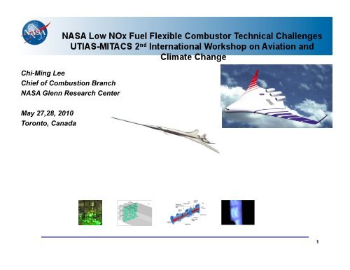
<strong>Chi</strong>-<strong>Ming</strong> <strong>Lee</strong><br />
<strong>Chi</strong>ef <strong>of</strong> <strong>Combustion</strong> <strong>Branch</strong><br />
<strong>NASA</strong> <strong>Glenn</strong> <strong>Research</strong> Center<br />
May 27,28, 2010<br />
Toronto, Canada<br />
1
ERA/SFW System Level Metrics<br />
…. technology for improving noise, emissions, & performance<br />
CORNERS OF THE<br />
TRADE SPACE<br />
Noise<br />
(cum below Stage 4)<br />
LTO NOx Emissions<br />
(below CAEP 6)<br />
Performance:<br />
Aircraft Fuel Burn<br />
Performance:<br />
Field Length<br />
N+1 (2015)***<br />
Generation<br />
Conventional Configurations<br />
relative to 1998 reference<br />
N+2 (2020)***<br />
Generation<br />
Unconventional Configurations<br />
relative to 1998 reference<br />
N+3 (2025)***<br />
Generation<br />
Advanced Aircraft Concepts<br />
relative to user-defined reference<br />
-32 dB -42 dB -71dB<br />
-60% -75% better than -75%<br />
-33%** -40%** better than -70%<br />
-33% -50% exploit metro-plex* concepts<br />
***Technology Readiness Level for key technologies = 4-6<br />
** Additional gains may be possible through operational improvements<br />
* Concepts that enable optimal use <strong>of</strong> runways at multiple airports within the metropolitan area<br />
Approach<br />
- Enable Major Changes in Engine Cycle/Airframe Configurations<br />
- Reduce Uncertainty in Multi-Disciplinary Design and Analysis Tools & Processes<br />
- Develop/Test/ Analyze Advanced Multi-Discipline Based Concepts & Technologies<br />
2
NOx emissions vs. the Overall Pressure Ra5o and SFC<br />
3
LTO (landing and take-<strong>of</strong>f) NOx Regulations Relative<br />
to CAEP 6 ( @ 30 OPR for Engines >89.0 KN <strong>of</strong> Thrust)<br />
120%<br />
100%<br />
80%<br />
60%<br />
40%<br />
20%<br />
CAEP6 ICAO NOx Regulations for Engines<br />
B777/GE90<br />
N+1, FAA CLEEN<br />
CAEP 6<br />
0%<br />
1986 1990 1994 1998 2002 2006 2010 2014 2018 2022<br />
Year<br />
GEnx -1B 55% below CAEP 6<br />
RR Trent 1000 ~50% below<br />
CAEP 6 (Predicted)<br />
PW 810 ~50% below CAEP 6<br />
(Estimated)<br />
N+2 Goal<br />
-75%<br />
4
Flametube<br />
Combustor<br />
Emissions Reduction - Technology to Product Transition<br />
<strong>NASA</strong> Program<br />
Sector<br />
Combustor<br />
<strong>NASA</strong> Project will develop and<br />
demonstrate low emissions to a<br />
technology readiness level (TRL) 6<br />
Full Annular<br />
Combustor<br />
Engine<br />
Integration<br />
TRL- 3 TRL- 4 TRL- 5 TRL- 6<br />
Industry Product Integration<br />
Market conditions and available technology<br />
improvements determine opportunity to<br />
launch new product engine<br />
“Off-Ramp” for Technology<br />
Industry:<br />
• Scaling to product engine size<br />
• Production engine design<br />
• Durability testing<br />
• Transient testing (altitude/flying test-bed)<br />
• Inclement weather testing<br />
• Manufacturing processes and tooling<br />
• Certification<br />
• Product support<br />
Certification and Entry Into Service<br />
TRL-9<br />
<strong>NASA</strong> and Industry Partnership for Low-Emission Combustor Technology Development !<br />
Followed by Possible Industry Certification and Product Implementation!<br />
5
Active<br />
<strong>Combustion</strong><br />
Control<br />
Methods<br />
Fuel<br />
Fuel Actuators<br />
Synergistic Technologies to Enable<br />
Ultra-Low Emissions <strong>Combustion</strong><br />
Feedback<br />
Sensors<br />
Manufacturing<br />
Processes<br />
Ultra-Low<br />
Emissions<br />
<strong>Combustion</strong><br />
Combustor<br />
and<br />
Fuel System<br />
Dynamics<br />
Materials<br />
Facilities for<br />
Realistic<br />
Test Conditions<br />
Fuel Injection<br />
Dynamics<br />
and<br />
Flameholding<br />
6
Fuel Flexible/Low Emissions<br />
Combustor Technical Challenges<br />
• Injector/Mixer Design<br />
• Active <strong>Combustion</strong> Control<br />
• High Temperature <strong>Combustion</strong> Liner<br />
Fuel<br />
Staging<br />
CMC<br />
Liners<br />
Instability<br />
Control<br />
7
Injector/Mixer Design Challenge<br />
8
75% Nox Reduction Injector Development<br />
• Advanced Injector Concept<br />
• Fuel/Air Mixing<br />
• Ignition<br />
9
Fischer-Tropsch & Jet A Fuel Analysis<br />
Test F-T Jet A<br />
Total Acid Number (mg KOH/g) 0.002 0.00<br />
Aromatics (% vol) 0.0 19<br />
Mercaptan Sulfur (% mass) 0.000 0.000<br />
Total Sulfur (% mass) 0.00 0.0<br />
Distillation<br />
Initial Boiling Point (°C) 149<br />
10% Recovered (°C) 162 180<br />
20% Recovered (°C) 163<br />
50% Recovered (°C) 168 212<br />
90% Recovered (°C) 184 251<br />
End Point (°C) 196<br />
Residue (% vol) 0.9 1.3<br />
Loss (% vol) 0.4 0.9<br />
Flash Point (°C) 44 51<br />
API Gravity @ 60°F 60.5<br />
Freezing Point (°C) -55 -48<br />
Viscosity @ -20°C (mm²/s) 2.6 5.2<br />
Net Heat <strong>of</strong> <strong>Combustion</strong> (MJ/kg) 44.2<br />
Test F-T Jet A<br />
Hydrogen Content (% mass) 15.6<br />
Smoke Point (mm) 40.0 21<br />
Copper Strip Corrosion (2 h @<br />
100°C)<br />
1a<br />
Thermal Stability @ 260°C<br />
Change in Pressure (mmHg)<br />
Tube Deposit Rating, Visual<br />
Existent Gum (mg/100 mL)
Time--><br />
C 8<br />
C 9<br />
C 10<br />
C 11<br />
F-T Fuel Analysis<br />
C 12<br />
5 10 15 20 25 30<br />
C 13<br />
C 14<br />
C 15<br />
5172 F-T Kerosene<br />
C 16<br />
Syntroleum<br />
4909 S-8<br />
C 17<br />
C 18<br />
C 19<br />
11
Concentration<br />
0<br />
Time--><br />
C 7<br />
C 8<br />
Fischer-Tropsch & JP-8 Fuel Analysis<br />
C 8<br />
C 9<br />
C 10<br />
C 11<br />
C 12<br />
C 13<br />
C 14<br />
C 15<br />
C 16<br />
C 17<br />
5 10 15 20 25 30<br />
Time<br />
C 18<br />
Shell<br />
F-T<br />
JP-8<br />
C 19<br />
12
JP8, 50-50 Blend, and FT-2 Comparisons<br />
Video Images, with flow from left to<br />
right<br />
Comparison showing average flame length and luminous intensity for T3 = 1030°F<br />
13
Advanced Subsonic Combustor Rig (ASCR)<br />
Alternative Fuels Establishment (cont’d)<br />
14
ASCR Plenum Design and Fabrication (cont’d)<br />
15
Active <strong>Combustion</strong> Control Challenge<br />
16
Ultra-Lean-Burning Combustors<br />
Are More Susceptible to Thermo-Acoustic Instabilities<br />
1. Higher-performance<br />
fuel injectors: more<br />
turbulence<br />
3. More uniform temperature and<br />
composition<br />
5. Experience in ground-power gas-turbines<br />
2. Reduced film cooling: reduced<br />
damping<br />
4. No dilution holes: reduced<br />
flame-holding<br />
17
<strong>Combustion</strong> Instability Control Strategy<br />
Objective: Suppress combustion thermo-acoustic instabilities when they<br />
occur<br />
Φ’<br />
+<br />
+ Fuel-air<br />
Mixture system<br />
<strong>Combustion</strong><br />
Process<br />
Actuator<br />
Closed-Loop Self-Excited System<br />
Controller<br />
Combustor<br />
Acoustics<br />
Natural feed-back process<br />
Artificial control process<br />
Sensor<br />
P’<br />
18
Long Term Goal for Active <strong>Combustion</strong> Control<br />
• Improve fundamental understanding <strong>of</strong> the<br />
combustor processes<br />
in order to…<br />
• More effectively integrate multi-point combustor<br />
design, controls, sensor, and actuator technologies<br />
to provide…<br />
– An intelligent fuel/air management system with<br />
temporal and spatial fuel modulation for<br />
• Instability avoidance/suppression<br />
– Thermoacoustics, blowout<br />
• Pattern factor control<br />
• Emissions minimization<br />
to enable…<br />
� Combustors with extremely low emissions<br />
throughout the engine operating envelope<br />
19
Active <strong>Combustion</strong> Control<br />
… In order to achieve 75% NOx reduction, it is necessary<br />
to demonstrate the capability to detect and suppress<br />
combustor instabilities for these very low emission<br />
combustors in order to enable efficient combustor<br />
operation at all conditions.<br />
• Develop sensor, actuation, high temperature electrical components for<br />
processing control signals, and control methodologies for integrated<br />
demonstration with the low emissions concepts<br />
• Utilize the flametube and sector combustor test capability<br />
� Goal - Keep pressure oscillation to within 1% <strong>of</strong> nominal at all<br />
power conditions in a sector rig indicative <strong>of</strong> a 75% NOx reduction<br />
combustor (TRL 5).<br />
20
Active <strong>Combustion</strong> Control<br />
<strong>Combustion</strong> Instability Dynamics Simulation <strong>of</strong> an advanced, low-emissions combustor prototype<br />
2 dynamic pressure transducers,<br />
P 31,& P 32<br />
2 1-element traversing<br />
probes<br />
dynamic pressure transducer,<br />
P 4DynUp, semi-infinite coil<br />
5-element probe<br />
CE5B-STAND 1 TEST RIG SCHEMATIC<br />
dynamic pressure transducer,<br />
P 4DynDn, semi-infinite coil<br />
Simulation Features<br />
• Physics-based, Sectored<br />
1-D, reacting<br />
• Time-accurate<br />
• Computationally efficient<br />
area transitions<br />
• Upstream and<br />
Downstream boundary<br />
conditions modeled to<br />
match rig<br />
CE5B-STAND 1 SIMULATION LAYOUT<br />
21
SiC Pressure Sensor Status<br />
• The design, fabrication, and testing <strong>of</strong> a SiC dynamic pressure sensor is ongoing. These activities<br />
include both extending the sensor material structure to higher temperatures as well as characterizing<br />
the present pressure sensor structure.<br />
• The work includes sensor fabrication (<strong>NASA</strong> GRC Microsystems Fabrication Clean Room) and<br />
packaging <strong>of</strong> pressure sensor (Sienna Technologies, Inc.)<br />
• Collaborating with Sienna Technologies, Inc. to develop a high temperature sealing glass with high<br />
glass transformation temperature to support pressure sensor operation at 800 o C. A new glass mix<br />
was applied on a dummy SiC chip and an old AlN header and both passed the hermiticity and<br />
adhesion tests (Figure 1).<br />
• Packaging <strong>of</strong> several sensors with the modified MEMS-DCA package capable <strong>of</strong> operating at 800 o C<br />
(Figure 2) is underway. These sensors were fabricated with a high temperature metallization<br />
approach which is a modified version <strong>of</strong> the existing metallization scheme (Ti/TaSi 2 /Pt). The result is<br />
a baseline for subsequent tests with sensors fabricated with a next generation metallization scheme.<br />
• Meetings have been held related to testing in the research combustor in CE-5. Required pressure<br />
fittings have been ordered and, when they arrive, a temperature gradient test will be conducted to<br />
determine how long <strong>of</strong> a sensor will be needed for the combustor testing. This information will be fed<br />
to Sienna Technologies for sensor construction.<br />
Figure 1 Newly developed 800 o C sealing glass demonstrated on a<br />
dummy sensor and AlN package header.<br />
Figure 2: Modified MEMS-DCA package to support<br />
800˚C pressure sensor operation.<br />
22
SiC Electronics Status<br />
• Building on world-record long-term operation <strong>of</strong> high temperature SiC electronics circuits<br />
(e.g., the differential amplifier in Figs. 1 and 2), we will be fabricating the next generation <strong>of</strong><br />
SiC electronics with increased complexity and transistor count.<br />
• In-package integration <strong>of</strong> SiC electronics with pressure sensors allows processing <strong>of</strong> sensor<br />
signals in-situ, improving the accuracy and reliability <strong>of</strong> the data in harsh environments.<br />
• Test structures are being fabricated in the <strong>NASA</strong> GRC Microsystems Fabrication Laboratory<br />
to verify the newly developed multilevel interconnect process, which will be used to<br />
configure tens <strong>of</strong> SiC transistors in integrated circuits.<br />
• A prototype 500 °C SiC integrated circuit amplifier and analog-to-digital (A/D) converter for<br />
use with an SiC dynamic pressure sensor has been designed. Fig. 3 shows the amplifier<br />
design. Fabrication <strong>of</strong> wafers with these electronics will begin in 1 month and should be<br />
completed 10 months later, after which the circuits will be packaged and tested.<br />
30µm<br />
Fig. 1. Differential amplifier circuit<br />
using two SiC transistors.<br />
Fig. 2. Diff amp test waveforms<br />
showing
Active <strong>Combustion</strong> Instability Control Via Fuel Modulation<br />
High-temperature sensors<br />
and electronics<br />
High-frequency fuel delivery<br />
system and models<br />
Physics-based instability models<br />
Emissions Probe<br />
Fuel<br />
Valve<br />
Advanced control methods<br />
+<br />
Pressure from +<br />
Fuel lines, Injector Fuel Modulation + Combustor Pressure<br />
Flame<br />
& <strong>Combustion</strong><br />
Phase Shift<br />
Controller<br />
White Noise<br />
Filter<br />
Combustor Instrumentation<br />
(pressures, temp’s)<br />
Fuel Injector<br />
Acoustics<br />
Realistic combustors, rigs for research<br />
NL<br />
Instability Pressure<br />
24
SiC Pressure Sensor Status<br />
• The design, fabrication, and testing <strong>of</strong> a SiC dynamic pressure sensor is ongoing.<br />
These activities include both extending the sensor material structure to higher<br />
temperatures as well as characterizing the present pressure sensor structure.<br />
• A landmark attempt was made to test the SiC pressure sensor with newly<br />
developed higher temperature (> 600 °C) packaging materials. The sensor was<br />
pressurized and measurement taken at various temperatures up to 750 C.<br />
• Pressure measurement at 750 °C indicated a net output <strong>of</strong> approximately 7 mV fullscale<br />
at 500 psi. While the observed instability in the device prevented further<br />
testing, the result validates the concept <strong>of</strong> using piezoresistive based SiC pressure<br />
sensors for measurement in 750 °C environment.<br />
25
SiC Electronics Status 03/22/2010<br />
• A wafer <strong>of</strong> multilevel interconnect test structures is approximately 50% completed and should be finished<br />
in about 6 weeks. These test structures will verify the newly developed multilevel interconnect process<br />
which will be used to configure tens <strong>of</strong> SiC transistors in integrated circuits for use at temperatures to 500<br />
°C. Figure 1 shows probe testing <strong>of</strong> 8-µm-wide vias through the overlying dielectric layer to the SiC<br />
substrate <strong>of</strong> the test wafer. A 4-µm via, at right, is too small to probe test. A via size <strong>of</strong> 4 µm will enable a<br />
transistor gate width <strong>of</strong> 2 µm for high density integrated circuits. Fabrication <strong>of</strong> such small features is<br />
technically challenging in a class 100 research cleanroom such as ours, yet is important to enable the<br />
fabrication <strong>of</strong> more complex integrated circuits with greater functionality. So far, we have achieved good<br />
results with the smallest size test structures.<br />
• Masks for a SiC integrated circuits have been designed. Fabrication <strong>of</strong> these circuits will begin after the<br />
multilevel interconnect test structures successfully pass operational verification testing on a probe station.<br />
These circuits should be completed by the end <strong>of</strong> January, 2011. Circuits to be fabricated include a 500 °C<br />
SiC integrated circuit amplifier (shown in Fig. 2) for use with an SiC dynamic pressure sensor.<br />
Fig. 1 - Probe testing <strong>of</strong> 8-µm-wide vias through dielectric layer<br />
<strong>of</strong> interconnect test structure wafer. A 4-µm via is visible at right.<br />
Fig. 2 - Design <strong>of</strong> SiC amplifier for<br />
dynamic pressure sensor.<br />
26
High Temperature Combustor Liner Challenge<br />
Objectives: Investigate CMC combustor liner materials, identify issues<br />
challenging CMC incorporation into engines, mitigate issues as possible<br />
Issues for CMC Liner –<br />
Durability –<br />
Insufficient data – both long term coupon and<br />
relevant engine environment<br />
Mitigation – In-house durability testing,<br />
coupon creep/fatigue/etc testing, HPBR,<br />
Subcomponent (NRA) testing.<br />
Advanced Coatings – improved coating compositions,<br />
erosion, spallation, repairability<br />
Mitigation - In-house research effort on advanced coatings, HPBR investigations, insufficient funds for repairability<br />
Integration – Attachment design & fretting coatings<br />
Mitigation - NRA for attachment design (?), in-house investigation in fretting coatings, coeff friction, various materials etc<br />
27
ERA CMC LINER -Overview<br />
Objectives: Investigate CMC combustor liner materials, identify issues<br />
challenging CMC incorporation into engines, mitigate issues as possible<br />
Approach:<br />
• Investigate basic properties <strong>of</strong> relevant CMC<br />
• Develop high coatings<br />
• NRA to obtain subcomponents<br />
• Collaborate extensively with Engine companies<br />
• Test subcomponents in (hot) engine vibratory environment<br />
18.5”<br />
GE 7FA<br />
Benefits:<br />
CMC combustor liner enables new engine designs incorporating higher<br />
engine temperatures and reduced cooling air flows<br />
Status:<br />
42”<br />
• Issues with CMC combustor liner identified with Engine company input<br />
• Basically on schedule – NRA may result in delays<br />
• Task planned, budget allocated<br />
• Selected baseline material<br />
HiPerComp Type 2 – procurement<br />
• Plans for Subcomponent delivery via NRA<br />
• Coating systems selected, procurements underway<br />
• Test matrices developed for coupon testing w&w/o coatings<br />
28<br />
14”
ERA CMC LINER – Subtasks<br />
1. Liner material testing<br />
Issues –<br />
Durability insufficiently understood<br />
or proven<br />
Status –<br />
Coupon panels in procurement<br />
Testing procurements underway<br />
Changes to HPBR underway for hot cooling air<br />
2. Advanced Coating Development<br />
Issues –<br />
Temps pushed to 2800F – better coatings needed<br />
<strong>NASA</strong> coatings compared to GE coating<br />
Repair coatings?<br />
Status-<br />
on track, procurements underway<br />
3. CMC Engine Integration Issues<br />
3a –CMC Attachments<br />
Issues –<br />
CMC attachment design<br />
metal wear /vibratory environment<br />
chemical issues at high temp?<br />
Status -<br />
on track – insufficient bodies?<br />
NRA impact uncertain<br />
3b – Joining<br />
Issues –<br />
thermal expansion mismatch<br />
chemical interaction?<br />
Status – slow start<br />
4. Fuel modulation<br />
Issues –Higher temp piezos –<br />
from 250F to 400F<br />
Status –<br />
on track<br />
procurements finished by April 30<br />
29
ERA CMC Liner<br />
Material Testing<br />
Objectives:<br />
Investigate durability issues for GE HiPerComp Type 2 CMC for high<br />
temperature engine environments.<br />
Approach:<br />
Investigate basic durability properties <strong>of</strong> coupons – 2D uni-layup prepreg Hi-<br />
Nic-S, balanced (yr 1).<br />
Develop advanced high temperature<br />
coatings<br />
NRA to obtain subcomponents<br />
Collaborate closely with Engine companies<br />
Test subcomponents in simulated engine<br />
environment<br />
Benefits:<br />
CMC combustor liner enables higher temp engine, liner surface operating<br />
temperature to 2800F<br />
Status:<br />
• Prepreg SiC CMC panels ordered.<br />
• HPBR modifications underway<br />
• Subcomponents obtained by NRA<br />
30
ERA CMC Liner<br />
Material Testing- Environmental Barrier Coatings<br />
Objective-<br />
Develop and validate advanced 2800°F<br />
environmental barrier coating (EBC) systems<br />
for SiC/SiC CMC combustors for ERA engine<br />
demonstrations.<br />
Status -<br />
• GE contract plan discussed for combustor EBC testing and development<br />
• Quote received from Sulzer for first round <strong>of</strong> environmental barrier coating<br />
powders<br />
• Collaborative plan for Dense-Vertical Cracked (DVC) combustor EBC<br />
development also discussed with Praxair<br />
• Potential trial non-Si bond coats development<br />
• High Pressure Burner Rig fixtures designed and fabricated for thermal<br />
fatigue and environmental degradation tests <strong>of</strong> impingement and filmcooled<br />
CMC-EBC test coupons<br />
• High Pressure Burner Rig Combustor being instrumented for CMC<br />
combustor segment rig fixture designs and testing<br />
• High pressure burner rig cooling air capability improved (up 600 psi) and<br />
fuel is being improved to accommodate planned higher mass-flow rate tests<br />
• Simulated thermal gradient fatigue laser rig also ready for 2 inch diameter<br />
CMC-EBC specimen thermal fatigue testing<br />
• Biaxial stress <strong>of</strong> heated CMC ring-on-ring test analyzed<br />
31
Objectives:<br />
ERA CMC Liner<br />
Integration Technology - Attachments<br />
Investigate fretting/wear/erosion issues<br />
involved with integrating CMCs into<br />
high temperature, dynamic engine<br />
environments. High temperature fretting<br />
coatings development required to<br />
protect metal components<br />
Approach:<br />
• Investigate basic properties <strong>of</strong> relevant<br />
materials<br />
• Develop high temperature fretting<br />
coatings<br />
• NRA to obtain subcomponents<br />
• Collaborate with Engine companies<br />
• Test subcomponents in (hot) engine<br />
vibratory environment<br />
Benefits:<br />
Enable integrating <strong>of</strong> critical CMC<br />
components<br />
Status:<br />
• Planning meetings with RXC/RXN/GE to<br />
identify R&D efforts is on-going.<br />
Collaborating with GE to develop<br />
needed data.<br />
• Rehabbing a high temperature fretting<br />
rig to evaluate samples at up to 1832 F.<br />
• Fretting coatings systems identified<br />
CMC-Metal oxidation-wear coatings: nitriding surfaces, nitride coatings<br />
(TiAlCrTaSiN among others) compared to superalloy substrates<br />
• HVOF nitride-bond coat cermet coatings may also be explored<br />
32
High Temperature Piezoelectric Material (GRC)<br />
� Improved operating temperature<br />
� Improved coercive field<br />
� Improved remenant polarization<br />
ERA – CMC Liner - Alp Sehirlioglu<br />
Fuel Modulation with HT Piezos<br />
High Temperature<br />
Piezoelectric Actuators<br />
Related Publications:<br />
Actuator Characterization<br />
- MTS Dynamic Load<br />
Application (up to 2kHz)<br />
- Mitutoyo Laser Micrometer<br />
Displacement measurement:<br />
3200 scan per second<br />
- ATS Furnace –with windows<br />
for laser access.<br />
- DC power supply, amplifier,<br />
Agilent 4294A Impedance<br />
Analyzer<br />
A. Sehirlioglu, A. Sayir, and F. Dynys, J. Am. Ceram. Soc., 91 [9], 2910 (2008).<br />
A. Sehirlioglu, A. Sayir, and F. Dynys, J. Appl. Phys. 106, 014102 (2009).<br />
A. Sehirlioglu, A. Sayir, and F. Dynys, in publication, J. Am. Ceram Soc., (2010).<br />
A. Sehirlioglu, A. Sayir, F. Dynys, K. Nittala, and J. Jones submitted to J. Am. Ceram<br />
Soc., (2010).<br />
33
Conclusion:<br />
Low NO x, Fuel-Flexible<br />
<strong>Combustion</strong> System<br />
Advanced Aircraft Concept<br />
GTF Engine<br />
Systems modeling<br />
• Flexible fuel staging<br />
• Mission pr<strong>of</strong>iling for<br />
emissions management<br />
Propulsion Contributions<br />
• Improved propulsion efficiency<br />
• Higher thermal efficiency<br />
<strong>Combustion</strong> Contributions<br />
• Lower NOx Emissions<br />
• Improved fuel-air mixing<br />
• Advanced Active Controls<br />
• Fuel Flexibility<br />
2002<br />
Hybrid Wing-Body Aircraft<br />
Experimental validation / verification<br />
• Emissions and atmospheric mixing sampling<br />
• In-flight measurement<br />
<strong>Combustion</strong> System Contributions<br />
• Improved thermal mgt<br />
• Light weight structures<br />
Low-NOx Combustor<br />
Materials Contributions<br />
• CMC combustor liners with reduced cooling<br />
• Improved high temperature durability<br />
Fundamental research<br />
CFD modeling; improved diagnostics; experimental techniques; acoustics physics; materials, etc<br />
34