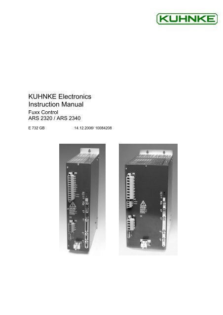
Fuxx Control - ARS 2320 / ARS 2340 Instruction Manual - Kuhnke
Fuxx Control - ARS 2320 / ARS 2340 Instruction Manual - Kuhnke
Fuxx Control - ARS 2320 / ARS 2340 Instruction Manual - Kuhnke

You also want an ePaper? Increase the reach of your titles
YUMPU automatically turns print PDFs into web optimized ePapers that Google loves.
KUHNKE Electronics<br />
<strong>Instruction</strong> <strong>Manual</strong><br />
<strong>Fuxx</strong> <strong>Control</strong><br />
<strong>ARS</strong> <strong>2320</strong> / <strong>ARS</strong> <strong>2340</strong><br />
E 732 GB 14.12.2006/ 10084208
<strong>Fuxx</strong> <strong>Control</strong> <strong>ARS</strong> <strong>2320</strong> / <strong>ARS</strong> <strong>2340</strong> KUHNKE Automation<br />
This instruction manual is primarily intended for use by design, project and development engineers. It does not contain any availability<br />
information. Data is only given to describe the product and must not be regarded as guaranteed properties in the legal sense. Any<br />
claims for damages - on whatever legal grounds - are excluded except for instances of deliberate intent or gross negligence on our<br />
part.<br />
We reserve the rights for errors, omissions and modifications.<br />
Reproduction even of extracts only with the editor's express and written prior consent.<br />
2 E 732 GB<br />
14.12.2006
KUHNKE Automation <strong>Fuxx</strong> <strong>Control</strong> <strong>ARS</strong> <strong>2320</strong> / <strong>ARS</strong> <strong>2340</strong><br />
Copyrights<br />
The information and data in this document have been composed to the best of our knowledge.<br />
However, deviations between the document and the product cannot be excluded entirely. For the<br />
devices and the corresponding software in the version handed out to the customer, KUHNKE<br />
AUTOMATION guarantees the contractual use in accordance with the user documentation. In the<br />
case of serious deviations from the user documentation, KUHNKE AUTOMATION has the right and<br />
the obligation to repair, unless it would involve an unreasonable effort. A possible liability does not<br />
include deficiencies caused by deviations from the operating conditions intended for the device and<br />
described in the user documentation.<br />
KUHNKE AUTOMATION does not guarantee that the products meet the buyer’s demands and<br />
purposes or that they work together with other products selected by the buyer. KUHNKE<br />
AUTOMATION does not assume any liability for damages resulting from the combined use of its<br />
products with other products or resulting from improper handling of machines or systems.<br />
KUHNKE AUTOMATION GmbH reserves the right to modify, amend, or improve the document or the<br />
product without prior notification.<br />
This document may, neither entirely nor in part, be reproduced, translated into any other natural or<br />
machine-readable language nor transferred to electronic, mechanical, optical or any other kind of data<br />
media, without expressive authorisation by the author.<br />
Trademarks<br />
Any product names in this document may be registered trademarks. The sole purpose of any<br />
trademarks in this document is the identification of the corresponding products.<br />
ServoCommander is a registered trademark<br />
Microsoft and Windows are either registered trademarks or trademarks of Microsoft Corporation in the<br />
United States and/or other countries.<br />
KUHNKE Automation GmbH & Co. KG<br />
Lütjenburger Straße 101<br />
23714 Malente<br />
Telefon (0 45 23) 4 02-0<br />
Telefax (0 45 23) 40 22 47<br />
E-Mail sales@kuhnke.de<br />
Internet www.kuhnke.de<br />
E 732 GB 3<br />
14.12.2006
<strong>Fuxx</strong> <strong>Control</strong> <strong>ARS</strong> <strong>2320</strong> / <strong>ARS</strong> <strong>2340</strong> KUHNKE Automation<br />
TABLE OF CONTENTS:<br />
1 GENERAL.........................................................................................................14<br />
1.1 Documentation .......................................................................................14<br />
1.2 Scope of supply ......................................................................................15<br />
2 SAFETY NOTES FOR ELECTRICAL DRIVES AND CONTROLS...................17<br />
2.1 Symbols and signs .................................................................................17<br />
2.2 General notes .........................................................................................17<br />
2.3 Danger resulting from misuse.................................................................19<br />
2.4 Safety notes............................................................................................19<br />
2.4.1 General safety notes..................................................................19<br />
2.4.2 Safety notes for assembly and maintenance .............................21<br />
2.4.3 Protection against contact with electrical parts ..........................22<br />
2.4.4 Protection against electrical shock by means of protective extralow<br />
voltage (PELV) ....................................................................23<br />
2.4.5 Protection against dangerous movements.................................23<br />
2.4.6 Protection against contact with hot parts ...................................24<br />
2.4.7 Protection during handling and assembly ..................................25<br />
3 PRODUCT DESCRIPTION...............................................................................26<br />
3.1 General...................................................................................................26<br />
3.2 Power supply ..........................................................................................28<br />
3.2.1 Three-phase AC power supply...................................................28<br />
3.2.2 DC-link coupling, DC-supply ......................................................28<br />
3.2.3 Mains fuse .................................................................................28<br />
3.3 Brake chopper ........................................................................................29<br />
3.4 Communication interfaces ......................................................................29<br />
3.4.1 RS232 interface .........................................................................29<br />
3.4.2 CAN bus ....................................................................................30<br />
3.4.3 Profibus......................................................................................30<br />
3.4.4 I/O functions and device control.................................................30<br />
4 TECHNICAL DATA ..........................................................................................32<br />
4.1 <strong>Control</strong> and display elements .................................................................33<br />
4.2 Power supply [X9]...................................................................................34<br />
4.3 Motor connection [X6].............................................................................35<br />
4.3.1 Current derating.........................................................................35<br />
4.4 Safe standstill and 24V supply [X3] ........................................................37<br />
4 E 732 GB<br />
14.12.2006
KUHNKE Automation <strong>Fuxx</strong> <strong>Control</strong> <strong>ARS</strong> <strong>2320</strong> / <strong>ARS</strong> <strong>2340</strong><br />
4.5 Angle encoder connection [X2A] and [X2B]............................................37<br />
4.5.1 Resolver connection [X2A].........................................................38<br />
4.5.2 Encoder connection [X2B] .........................................................39<br />
4.6 Communication interfaces ......................................................................40<br />
4.6.1 RS232 [X5] ................................................................................40<br />
4.6.2 CAN bus [X4] .............................................................................40<br />
4.6.3 I/O interface [X1]........................................................................41<br />
4.6.4 Incremental encoder input [X10] .................................42<br />
4.6.5 Incremental encoder output [X11]..............................................43<br />
5 FUNCTION OVERVIEW ...................................................................................44<br />
5.1 Motors ....................................................................................................44<br />
5.1.1 Synchronous servo motors ........................................................44<br />
5.1.2 Linear motors.............................................................................44<br />
5.2 <strong>ARS</strong> 2300 servo positioning controller functions ....................................44<br />
5.2.1 Compatibility ..............................................................................44<br />
5.2.2 Pulse width modulation (PWM)..................................................45<br />
5.2.3 Setpoint management................................................................46<br />
5.2.4 Torque-controlled mode.............................................................46<br />
5.2.5 Speed-controlled mode..............................................................47<br />
5.2.6 Torque-limited speed control......................................................47<br />
5.2.7 Synchronization with external clock sources..............................47<br />
5.2.8 Load torque compensation in the case of vertical axes .............48<br />
5.2.9 Positioning and position control .................................................48<br />
5.2.10 Synchronization, electrical transmission .....................48<br />
5.2.11 Brake management....................................................................49<br />
5.3 Positioning control ..................................................................................49<br />
5.3.1 Overview....................................................................................49<br />
5.3.2 Relative positioning....................................................................50<br />
5.3.3 Absolute positioning...................................................................50<br />
5.3.4 Driving profile generator.............................................................50<br />
5.3.5 Homing ......................................................................................51<br />
5.3.6 Positioning sequences ...............................................................52<br />
5.3.7 Optional stop input .....................................................................53<br />
5.3.8 Continuous-path control with linear interpolation .......................53<br />
5.3.9 Time-synchronized multi-axis positioning...................................54<br />
6 FUNCTIONAL SAFETY TECHNOLOGY..........................................................55<br />
6.1 General, intended use ............................................................................55<br />
E 732 GB 5<br />
14.12.2006
<strong>Fuxx</strong> <strong>Control</strong> <strong>ARS</strong> <strong>2320</strong> / <strong>ARS</strong> <strong>2340</strong> KUHNKE Automation<br />
6.2 Integrated "safe stop" function................................................................57<br />
6.2.1 General / description of "safe stop" function ..............................57<br />
6.2.2 Safe holding brake activation.....................................................59<br />
6.2.3 Mode of operation / timing: ........................................................60<br />
6.2.4 Application examples .................................................................63<br />
6.2.4.1 Emergency stop circuit: .........................................................................63<br />
6.2.4.2 Safety door monitoring...........................................................................65<br />
7 MECHANICAL INSTALLATION.......................................................................67<br />
7.1 Important notes.......................................................................................67<br />
7.2 Device view ............................................................................................70<br />
7.3 Installation ..............................................................................................73<br />
8 ELECTRICAL INSTALLATION ........................................................................75<br />
8.1 Connector configuration..........................................................................75<br />
8.2 Complete <strong>ARS</strong> 2300 system...................................................................77<br />
8.3 Connection at the <strong>ARS</strong> <strong>2320</strong> servo positioning controller: Power supply<br />
and braking resistor [X9].........................................................................79<br />
8.3.1 Configuration at the <strong>ARS</strong> <strong>2320</strong> servo positioning controller [X9]79<br />
8.3.2 Mating connector [X9] at the <strong>ARS</strong> <strong>2320</strong>.....................................79<br />
8.3.3 Pin assignment [X9] at the <strong>ARS</strong> <strong>2320</strong>........................................79<br />
8.3.4 Connection: External braking resistor [X9] at the <strong>ARS</strong> <strong>2320</strong>......80<br />
8.3.5 Type and configuration of cable [X9] at the <strong>ARS</strong> <strong>2320</strong> ..............80<br />
8.3.6 Connection notes concerning [X9] at the <strong>ARS</strong> <strong>2320</strong> ..................81<br />
8.4 Connection at the <strong>ARS</strong> <strong>2340</strong> servo positioning controller: Power supply<br />
[X9] and braking resistor [X9A] ...............................................................81<br />
8.4.1 Configuration at the <strong>ARS</strong> <strong>2340</strong> servo positioning controller [X9]81<br />
8.4.2 Mating connector [X9] at the <strong>ARS</strong> <strong>2340</strong>.....................................81<br />
8.4.3 Pin assignment [X9] at the <strong>ARS</strong> <strong>2340</strong>........................................82<br />
8.4.4 Type and configuration of cable [X9] at the <strong>ARS</strong> <strong>2340</strong> ..............82<br />
8.4.5 Connection notes concerning [X9] at the <strong>ARS</strong> <strong>2340</strong> ..................82<br />
8.4.6 Connection: External braking resistor [X9A] at the <strong>ARS</strong> <strong>2340</strong> ...83<br />
8.4.7 Configuration [X9A] at the <strong>ARS</strong> <strong>2340</strong>.........................................83<br />
8.4.8 Mating connector [X9A] at the <strong>ARS</strong> <strong>2340</strong> ..................................83<br />
8.4.9 Pin assignment [X9A] at the <strong>ARS</strong> <strong>2340</strong> .....................................83<br />
8.4.10 Connection notes concerning [X9A] at the <strong>ARS</strong> <strong>2340</strong>................84<br />
8.5 Connection: Safe standstill and 24V supply [X3] ....................................84<br />
8.5.1 Configuration on the device [X3]................................................84<br />
8.5.2 Mating connector [X3] ................................................................84<br />
6 E 732 GB<br />
14.12.2006
KUHNKE Automation <strong>Fuxx</strong> <strong>Control</strong> <strong>ARS</strong> <strong>2320</strong> / <strong>ARS</strong> <strong>2340</strong><br />
8.5.3 Pin assignment [X3] ...................................................................85<br />
8.5.4 Cable type and configuration: 24VDC power supply [X3] ..........85<br />
8.5.5 Connection notes [X3]................................................................85<br />
8.6 Connection: Motor [X6] and [X6A] ..........................................................86<br />
8.6.1 Configuration [X6] at the <strong>ARS</strong> <strong>2320</strong> ...........................................86<br />
8.6.2 Mating connector [X6] at the <strong>ARS</strong> <strong>2320</strong>.....................................86<br />
8.6.3 Configuration [X6] at the <strong>ARS</strong> <strong>2320</strong> ...........................................86<br />
8.6.4 Mating connector [X6] at the <strong>ARS</strong> <strong>2320</strong>.....................................86<br />
8.6.5 Configuration on the servo positioning controller [X6A] .............86<br />
8.6.6 Mating connector [X6A]..............................................................86<br />
8.6.7 Pin assignment [X6] ...................................................................86<br />
8.6.8 Type and configuration of cable [X6] and [X6A] at the <strong>ARS</strong> <strong>2320</strong>87<br />
8.6.9 Type and configuration of cable [X6] and [X6A] at the <strong>ARS</strong> <strong>2340</strong>87<br />
8.6.10 Connection notes concerning [X6] and [X6A] ............................88<br />
8.7 Connection: I/O communication [X1] ......................................................90<br />
8.7.1 Configuration on the device [X1]................................................92<br />
8.7.2 Mating connector [X1] ................................................................92<br />
8.7.3 Pin assignment [X1] ...................................................................93<br />
8.7.4 Cable type and configuration [X1] ..............................................94<br />
8.7.5 Connection notes [X1]................................................................94<br />
8.8 Connection: Resolver [X2A]....................................................................95<br />
8.8.1 Configuration on the device [X2A]..............................................95<br />
8.8.2 Mating connector [X2A]..............................................................95<br />
8.8.3 Pin assignment [X2A].................................................................95<br />
8.8.4 Cable type and configuration [X2A]............................................96<br />
8.8.5 Connection notes [X2A] .............................................................96<br />
8.9 Connection: Encoder [X2B] ....................................................................97<br />
8.9.1 Configuration on the device [X2B]..............................................97<br />
8.9.2 Mating connector [X2B]..............................................................97<br />
8.9.3 Pin assignment [X2B].................................................................97<br />
8.9.4 Cable type and configuration [X2B]............................................99<br />
8.9.5 Connection notes [X2B] ...........................................................100<br />
8.10 Connection: Incremental encoder input [X10].......................................101<br />
8.10.1 Configuration on the device [X10] ............................................101<br />
8.10.2 Mating connector [X10] ............................................................101<br />
8.10.3 Pin assignment [X10] ...............................................................102<br />
8.10.4 Cable type and configuration [X10] ..........................................102<br />
8.10.5 Connection notes [X10]............................................................102<br />
E 732 GB 7<br />
14.12.2006
<strong>Fuxx</strong> <strong>Control</strong> <strong>ARS</strong> <strong>2320</strong> / <strong>ARS</strong> <strong>2340</strong> KUHNKE Automation<br />
8.11 Connection: Incremental encoder output [X11].....................................103<br />
8.11.1 Configuration on the device [X11] ............................................103<br />
8.11.2 Mating connector [X11] ............................................................103<br />
8.11.3 Pin assignment [X11] ...............................................................104<br />
8.11.4 Cable type and configuration [X11] ..........................................104<br />
8.11.5 Connection notes [X11]............................................................104<br />
8.12 Connection: CAN bus [X4]....................................................................105<br />
8.12.1 Configuration on the device [X4]..............................................105<br />
8.12.2 Mating connector [X4] ..............................................................105<br />
8.12.3 Pin assignment [X4] .................................................................105<br />
8.12.4 Cable type and configuration [X4] ............................................106<br />
8.12.5 Connection notes [X4]..............................................................106<br />
8.13 Connection: RS232/COM [X5]..............................................................107<br />
8.13.1 Configuration on the device [X5]..............................................107<br />
8.13.2 Mating connector [X5] ..............................................................107<br />
8.13.3 Pin assignment [X5] .................................................................108<br />
8.13.4 Cable type and configuration [X5] ............................................108<br />
8.13.5 Connection notes [X5]..............................................................108<br />
8.14 Notes concerning safe and EMC-compliant installation........................109<br />
8.14.1 Definitions and terminology......................................................109<br />
8.14.2 General information concerning EMC ......................................109<br />
8.14.3 EMC ranges: First and second environment............................110<br />
8.14.4 EMC-compliant cabling ............................................................110<br />
8.14.5 Operation with long motor cables.............................................112<br />
8.14.6 ESD protection.........................................................................112<br />
9 START-UP......................................................................................................113<br />
9.1 General connection notes.....................................................................113<br />
9.2 Tools / material .....................................................................................113<br />
9.3 Connecting the motor ...........................................................................113<br />
9.4 Connecting the <strong>ARS</strong> 2300 servo positioning controller to the power<br />
supply ...................................................................................................114<br />
9.5 Connecting a PC ..................................................................................114<br />
9.6 Checking whether the system is ready for operation ............................114<br />
10 SERVICE FUNCTIONS AND ERROR MESSAGES.......................................115<br />
10.1 Protection and service functions...........................................................115<br />
10.1.1 Overview..................................................................................115<br />
10.1.2 Phase and mains failure detection ...........................................115<br />
8 E 732 GB<br />
14.12.2006
KUHNKE Automation <strong>Fuxx</strong> <strong>Control</strong> <strong>ARS</strong> <strong>2320</strong> / <strong>ARS</strong> <strong>2340</strong><br />
10.1.3 Overcurrent and short-circuit monitoring..................................116<br />
10.1.4 Overvoltage monitoring of the DC-link .....................................116<br />
10.1.5 Temperature monitoring of the heat sink .................................116<br />
10.1.6 Motor monitoring......................................................................116<br />
10.1.7 I²t monitoring............................................................................117<br />
10.1.8 Power monitoring of the internal brake chopper.......................117<br />
10.1.9 Start-up status .........................................................................117<br />
10.1.10 Rapid discharge of the DC-link ................................................117<br />
10.2 Operating mode and error messages ...................................................118<br />
10.2.1 Operating mode and error display............................................118<br />
10.3 Error / warning messages.....................................................................119<br />
11 TECHNOLOGIEMODULE ..............................................................................136<br />
11.1 PROFIBUS-DP-Interface......................................................................136<br />
11.1.1 Product description ..................................................................136<br />
11.1.2 Technical data..........................................................................136<br />
11.1.3 Pin assignments and cable specifications................................138<br />
11.1.3.1 Pin assignments ................................................................................. 138<br />
11.1.3.2 Mating connector ................................................................................ 138<br />
11.1.3.3 Cable type and configuration.............................................................. 138<br />
11.1.4 Termination and bus terminating resistors ...............................139<br />
11.2 SERCOS module..................................................................................140<br />
11.2.1 Product description ..................................................................140<br />
11.2.2 Technical data..........................................................................140<br />
11.2.3 Optical waveguide specification ...............................................141<br />
11.3 EA88 interface technology module .......................................................142<br />
11.3.1 Product description ..................................................................142<br />
11.3.2 Technical data..........................................................................142<br />
11.3.2.1 General data ....................................................................................... 142<br />
11.3.2.2 Digital inputs ....................................................................................... 143<br />
11.3.2.3 Digital outputs ..................................................................................... 143<br />
11.3.3 Pin assignment and cable specifications .................................144<br />
11.3.3.1 Power supply ...................................................................................... 144<br />
11.3.3.2 Pin assignments ................................................................................. 144<br />
11.3.4 Mating connector .....................................................................145<br />
11.3.5 Connection notes .....................................................................145<br />
11.4 General installation notes for technology modules ...............................146<br />
E 732 GB 9<br />
14.12.2006
<strong>Fuxx</strong> <strong>Control</strong> <strong>ARS</strong> <strong>2320</strong> / <strong>ARS</strong> <strong>2340</strong> KUHNKE Automation<br />
List of Figures:<br />
Figure 1: Type key ...........................................................................................................................26<br />
Figure 2: <strong>ARS</strong> <strong>2320</strong>: Current derating diagram ...............................................................................36<br />
Figure 3: <strong>ARS</strong> <strong>2340</strong>: Current derating diagram ...............................................................................36<br />
Figure 4: <strong>ARS</strong> 2300 control structure ..............................................................................................45<br />
Figure 5: <strong>ARS</strong> 2300 servo positioning controller driving profiles.....................................................51<br />
Figure 6: Path program ....................................................................................................................52<br />
Figure 7: Linear interpolation between two data values ..................................................................53<br />
Figure 8: Servo positioning controller <strong>ARS</strong> <strong>2320</strong>: Installation space...............................................68<br />
Figure 9: Servo positioning controller <strong>ARS</strong> <strong>2340</strong>: Installation space...............................................69<br />
Figure 10: Servo positioning controller <strong>ARS</strong> <strong>2320</strong>: Front view ..........................................................70<br />
Figure 11: Servo positioning controller <strong>ARS</strong> <strong>2340</strong>: Front view ..........................................................71<br />
Figure 12: Servo positioning controller <strong>ARS</strong> <strong>2320</strong>: Bottom view .......................................................72<br />
Figure 13: Servo positioning controller <strong>ARS</strong> <strong>2340</strong>: Bottom view .......................................................73<br />
Figure 14: Servo positioning controller <strong>ARS</strong> 2300: Mounting plate..................................................74<br />
Figure 15: Servo positioning controller <strong>ARS</strong> <strong>2320</strong>: Connection to the supply voltage and to the<br />
motor.................................................................................................................................75<br />
Figure 16: Servo positioning controller <strong>ARS</strong> <strong>2340</strong>: Connection to the supply voltage and to the<br />
motor.................................................................................................................................76<br />
Figure 17: Complete set-up of <strong>ARS</strong> 2300 with motor and PC ...........................................................78<br />
Figure 18: Pin assignment [X9] at the <strong>ARS</strong> -560/20-M: Supply and braking resistor........................81<br />
Figure 19: Pin assignment [X9] at the <strong>ARS</strong> <strong>2340</strong>: Supply .................................................................82<br />
Figure 20: Pin assignment [X9A] at the <strong>ARS</strong> <strong>2340</strong>: Braking resistor.................................................84<br />
Figure 21: Pin assignment [X3]: 24VDC power supply......................................................................85<br />
Figure 22: Pin assignment [X6] and [X6A]: Motor..............................................................................88<br />
Figure 23: Connecting a locking brake with high current demand (> 2A) to the device....................89<br />
Figure 24: Basic circuit diagram of connection [X1]...........................................................................91<br />
Figure 25: Pin assignment: Resolver connection [X2A] ....................................................................96<br />
Figure 26: Pin assignment: Analog incremental encoder - option [X2B] ........................................ 100<br />
Figure 27: Pin assignment: Incremental encoder with serial interface (e.g. EnDat, HIPERFACE) -<br />
option [X2B] ................................................................................................................... 100<br />
Figure 28: Pin assignment: Digital incremental encoder - option [X2B] ......................................... 101<br />
Figure 29: Pin assignment [X10]: Incremental encoder input......................................................... 103<br />
Figure 30: Pin assignment [X11]: Incremental encoder output....................................................... 104<br />
10 E 732 GB<br />
14.12.2006
KUHNKE Automation <strong>Fuxx</strong> <strong>Control</strong> <strong>ARS</strong> <strong>2320</strong> / <strong>ARS</strong> <strong>2340</strong><br />
Figure 31: CAN bus cabling example ............................................................................................. 106<br />
Figure 32: Pin assignment RS232 null modem cable [X5] ............................................................. 108<br />
Figure 33: Motor cable: Lengths of shields and cables .................................................................. 111<br />
Figure 34: PROFIBUS-DP interface: Front view............................................................................. 137<br />
Figure 35: PROFIBUS-DP interface: Connection with external terminating resistors.................... 139<br />
Figure 36: SERCOS module: Front view ........................................................................................ 141<br />
Figure 37: Position of the pin-and-socket connectors [X21] and [X22] at the front plate ............... 145<br />
E 732 GB 11<br />
14.12.2006
<strong>Fuxx</strong> <strong>Control</strong> <strong>ARS</strong> <strong>2320</strong> / <strong>ARS</strong> <strong>2340</strong> KUHNKE Automation<br />
List of Tables:<br />
Table 1: Scope of supply ................................................................................................................15<br />
Table 2: Connector set: DSUB and POWER connector.................................................................15<br />
Table 3: Connector set: DSUB connector ......................................................................................16<br />
Table 4: Technical data: Ambient conditions and qualification.......................................................32<br />
Table 5: Technical data: Dimensions and weight...........................................................................32<br />
Table 6: Technical data: Cable data...............................................................................................33<br />
Table 7: Technical data: Motor temperature monitoring.................................................................33<br />
Table 8: Display elements and RESET button ...............................................................................33<br />
Table 9: Technical data: Power data [X9].......................................................................................34<br />
Table 10: Technical data: Internal braking resistor [X9] or [X9A].....................................................34<br />
Table 11: Technical data: External braking resistor [X9] or [X9A]....................................................34<br />
Table 12: Technical data: Motor connection data [X6] .....................................................................35<br />
Table 13: Technical data: 24VDC supply [X3]..................................................................................37<br />
Table 14: Technical data: Resolver [X2A] ........................................................................................38<br />
Table 15: Technical data: Resolver interface [X2A] .........................................................................38<br />
Table 16: Technical data: Encoder evaluation [X2B]........................................................................40<br />
Table 17: Technical data: RS232 [X5]..............................................................................................40<br />
Table 18: Technical data: CAN bus [X4] ..........................................................................................40<br />
Table 19: Technical data: Digital inputs and outputs [X1] ................................................................41<br />
Table 20: Technical data: Analog inputs and outputs [X1] ...............................................................42<br />
Table 21: Technical data: Incremental encoder input [X10] .............................................................42<br />
Table 22: Technical data: Incremental encoder output [X11]...........................................................43<br />
Table 23: Output voltage at the motor terminals in the case of UZK = 560V.....................................45<br />
Table 24: Description of the requirements to be met for the categories in accordance with<br />
EN 954-1...........................................................................................................................55<br />
Table 25: EMERGENCY OFF and EMERGENCY STOP as per EN 60204-1.................................56<br />
Table 26: Stop categories.................................................................................................................57<br />
Table 27: Pin assignment [X9] at the <strong>ARS</strong> <strong>2320</strong>: Supply .................................................................79<br />
Table 28: Pin assignment [X9] at the <strong>ARS</strong> <strong>2320</strong>: External braking resistor .....................................80<br />
Table 29: Pin assignment [X9] at the <strong>ARS</strong> <strong>2340</strong>: Supply .................................................................82<br />
Table 30: Pin assignment [X9A] at the <strong>ARS</strong> <strong>2340</strong>: Braking resistor.................................................83<br />
Table 31: Pin assignment [X3]..........................................................................................................85<br />
12 E 732 GB<br />
14.12.2006
KUHNKE Automation <strong>Fuxx</strong> <strong>Control</strong> <strong>ARS</strong> <strong>2320</strong> / <strong>ARS</strong> <strong>2340</strong><br />
Table 32: Pin assignment [X6]: Motor...............................................................................................86<br />
Table 33: Motor temperature monitoring system and holding brake [X6A] ......................................87<br />
Table 34: Pin assignment: I/O communication [X1].........................................................................93<br />
Table 35: Pin assignment [X2A] .......................................................................................................95<br />
Table 36: Pin assignment: Analog incremental encoder - option [X2B] ...........................................97<br />
Table 37: Pin assignment: Incremental encoder with serial interface (e.g. EnDat, HIPERFACE) -<br />
option [X2B] ......................................................................................................................98<br />
Table 38: Pin assignment: Digital incremental encoder - option [X2B] ............................................99<br />
Table 39: Pin assignment [X10]: Incremental encoder input......................................................... 102<br />
Table 40: Pin assignment [X11]: Incremental encoder output....................................................... 104<br />
Table 41: Pin assignment CAN bus [X4] ....................................................................................... 105<br />
Table 42: Pin assignment RS232 interface [X5]............................................................................ 108<br />
Table 43: EMC requirements: First and second environment....................................................... 110<br />
Table 44: Operating mode and error display................................................................................. 118<br />
Table 45: Error messages ............................................................................................................. 119<br />
Table 46: Technical data: PROFIBUS-DP interface: Ambient conditions, dimensions and weight136<br />
Table 47: Technical data: PROFIBUS-DP interface: Interfaces and communication ................... 137<br />
Table 48: Pin assignment: PROFIBUS-DP interface..................................................................... 138<br />
Table 49: Technical data: SERCOS module: Ambient conditions, dimensions and weight.......... 140<br />
Table 50: Technical data: EA88 interface...................................................................................... 142<br />
Table 51: Digital inputs [X21]: EA88 interface ............................................................................... 143<br />
Table 52: Digital outputs [X22]: EA88 interface............................................................................. 143<br />
Table 53: EA88: Connector [X21] for 8 digital inputs..................................................................... 144<br />
Table 54: EA88: Connector [X22] for 8 digital outputs .................................................................. 144<br />
E 732 GB 13<br />
14.12.2006
<strong>Fuxx</strong> <strong>Control</strong> <strong>ARS</strong> <strong>2320</strong> / <strong>ARS</strong> <strong>2340</strong> KUHNKE Automation<br />
1 General<br />
1.1 Documentation<br />
This product manual is intended to ensure safe use of servo positioning controllers of the <strong>ARS</strong> 2300<br />
range of products. It contains safety notes which have to be complied with.<br />
Further information can be found in the following manuals of the <strong>ARS</strong> 2000 product range:<br />
� Software manual "Servo Positioning <strong>Control</strong>ler <strong>ARS</strong> 2000": Description of the device<br />
functionality and the software functions of the firmware including the RS232 communication.<br />
Description of the ServoCommander parameterisation program with instructions concerning the<br />
start-up of <strong>ARS</strong> 2000 servo positioning controllers.<br />
� Product <strong>Manual</strong> “Servo Positioning <strong>Control</strong>ler <strong>ARS</strong> 2100”: Description of the technical<br />
specifications and the device functionality as well as notes on the installation and the operation of<br />
the servo positioning controller <strong>ARS</strong> 2100.<br />
� Product manual "Servo Positioning <strong>Control</strong>ler <strong>ARS</strong> 2302 - 2310": Description of the technical<br />
data and the device functionality plus notes concerning the installation and operation of <strong>ARS</strong><br />
2302, 2305 and 2310 servo positioning controllers.<br />
� Product manual "Servo Positioning <strong>Control</strong>ler <strong>ARS</strong> <strong>2320</strong> and <strong>2340</strong>": Description of the<br />
technical data and the device functionality plus notes concerning the installation and operation of<br />
<strong>ARS</strong> <strong>2320</strong> and <strong>2340</strong> servo positioning controllers.<br />
� CANopen <strong>Manual</strong> “Servo Positioning <strong>Control</strong>ler <strong>ARS</strong> 2000“: Description of the implemented<br />
CANopen protocol as per DSP402.<br />
� PROFIBUS <strong>Manual</strong> “Servo Positioning <strong>Control</strong>ler <strong>ARS</strong> 2000”: Description of the implemented<br />
PROFIBUS-DP protocol.<br />
� SERCOS <strong>Manual</strong> “Servo Positioning <strong>Control</strong>ler <strong>ARS</strong> 2000”: Description of the implemented<br />
SERCOS functionality.<br />
The entire software functionality of the new <strong>ARS</strong> 2000 product range will be implemented in the<br />
course of a step-by-step development process.<br />
This version of the hardware manual contains functions of firmware version 3.2 and of firmware<br />
version 3.x, which is currently being prepared.<br />
Whenever relevant, special notes like are included in chapter headings and in the text block,<br />
indicating that the functions of firmware version 3.x are available.<br />
14 E 732 GB<br />
14.12.2006
KUHNKE Automation <strong>Fuxx</strong> <strong>Control</strong> <strong>ARS</strong> <strong>2320</strong> / <strong>ARS</strong> <strong>2340</strong><br />
1.2 Scope of supply<br />
The supply comprises:<br />
Table 1: Scope of supply<br />
1x<br />
Servo positioning controller <strong>ARS</strong> 2300<br />
Scope:<br />
1x Counterplug PHOENIX Mini-Combicon MC 1,5/ 6-GF-3,81with isolated<br />
cable bridge<br />
2x PHOENIX shield clamp Type SK20<br />
Mating connectors for power, control or rotary encoder connections are not part of the standard scope<br />
of supply. They can be ordered as accessories:<br />
Table 2: Connector set: DSUB and POWER connector<br />
1x<br />
1x<br />
<strong>ARS</strong> <strong>2320</strong> Power Connector set:<br />
Content:<br />
1x 11-pin Phoenix connector<br />
PC 4 HV/11-ST-7.62<br />
1x 4-pin Phoenix connector<br />
PC 4 HV/4-ST-7.62<br />
1x 2-pin Phoenix connector<br />
MSTB 2.5/2-ST-5.08<br />
1x 6-pin Phoenix connector<br />
MC 1.5/6-STF-3.81<br />
<strong>ARS</strong> <strong>2340</strong> Power Connector set:<br />
Content:<br />
1x 8-pin Phoenix connector<br />
PC 6/8-STF-10.16<br />
1x 4-pin Phoenix connector<br />
PC 6/4-STF-10.16<br />
1x 2-pin Phoenix connector<br />
MSTB 2.5/2-ST-5.08<br />
1x 6-pin Phoenix connector<br />
MC 1.5/6-STF-3.81<br />
part number: 683.800.03<br />
part number: 683.800.04<br />
E 732 GB 15<br />
14.12.2006
<strong>Fuxx</strong> <strong>Control</strong> <strong>ARS</strong> <strong>2320</strong> / <strong>ARS</strong> <strong>2340</strong> KUHNKE Automation<br />
Table 3: Connector set: DSUB connector<br />
1x<br />
Connector set: DSUB connector<br />
Content:<br />
3x 9-pin DSUB connector, male<br />
1x 9-pin DSUB connector, female<br />
4x DSUB housing for 9-pin DSUB<br />
connector<br />
1x 15-pin DSUB connector, male<br />
1x DSUB housing for 15-pin DSUB<br />
connector<br />
1x 25-pin DSUB connector, male<br />
1x DSUB housing for 25-pin DSUB<br />
connector<br />
part number: 683.800.00<br />
16 E 732 GB<br />
14.12.2006
KUHNKE Automation <strong>Fuxx</strong> <strong>Control</strong> <strong>ARS</strong> <strong>2320</strong> / <strong>ARS</strong> <strong>2340</strong><br />
2 Safety Notes for electrical drives<br />
and controls<br />
2.1 Symbols and signs<br />
Information<br />
Important informations and notes.<br />
Caution!<br />
The nonobservance can result in high property damage.<br />
DANGER!<br />
The nonobservance can result in property damages and in injuries to persons.<br />
Caution! High voltage.<br />
The note on safety contains a reference to a possibly occurring life dangerous voltage.<br />
2.2 General notes<br />
In the case of damage resulting from non-compliance of the safety notes in this manual KUHNKE<br />
AUTOMATION GmbH & Co KG will assume any liability.<br />
Prior to the initial use you must read the chapters Safety Notes for electrical drives and<br />
controls on page 17 and Notes concerning safe and EMC-compliant installation on page<br />
109.<br />
If the documentation in the language at hand is not understood accurately, please contact and inform<br />
your supplier.<br />
Sound and safe operation of the servo drive controller requires proper and professional transportation,<br />
storage, assembly and installation as well as proper operation and maintenance. Only trained and<br />
qualified personnel may handle electrical devices:<br />
E 732 GB 17<br />
14.12.2006
<strong>Fuxx</strong> <strong>Control</strong> <strong>ARS</strong> <strong>2320</strong> / <strong>ARS</strong> <strong>2340</strong> KUHNKE Automation<br />
TRAINED AND QUALIFIED PERSONNEL<br />
n the sense of this product manual or the safety notes on the product itself are persons who are<br />
sufficiently familiar with the project, the setup, assembly, commissioning and operation of the product<br />
as well as all warnings and precautions as per the instructions in this manual and who are sufficiently<br />
qualified in their field of expertise:<br />
� Education and instruction concerning the standards and accident prevention regulations for the<br />
application, or authorisation to switch devices/systems on and off and to ground them as per the<br />
standards of safety engineering and to efficiently label them as per the job demands.<br />
� Education and instruction as per the standards of safety engineering regarding the maintenance<br />
and use of adequate safety equipment.<br />
� First aid training.<br />
The following notes must be read prior to the initial operation of the system to prevent personal<br />
injuries and/or property damages:<br />
These safety notes must be complied with at all times.<br />
Do not try to install or commission the servo drive controller before carefully reading all<br />
safety notes for electrical drives and controllers contained in this document. These<br />
safety instructions and all other user notes must be read prior to any work with the servo<br />
drive controller.<br />
In case you do not have any user notes for the servo positioning controller, please<br />
contact your sales representative. Immediately demand these documents to be sent to<br />
the person responsible for the safe operation of the servo drive controller.<br />
If you sell, rent and/or otherwise make this device available to others, these safety notes<br />
must also be included.<br />
The user must not open the servo drive controller for safety and warranty reasons.<br />
Professional control process design is a prerequisite for sound functioning of the servo<br />
drive controller!<br />
DANGER!<br />
Inappropriate handling of the servo drive controller and non-compliance of the<br />
warnings as well as inappropriate intervention in the safety features may result in<br />
property damage, personal injuries, electric shock or in extreme cases even death.<br />
18 E 732 GB<br />
14.12.2006
KUHNKE Automation <strong>Fuxx</strong> <strong>Control</strong> <strong>ARS</strong> <strong>2320</strong> / <strong>ARS</strong> <strong>2340</strong><br />
2.3 Danger resulting from misuse<br />
DANGER!<br />
High electrical voltages and high load currents!<br />
Danger to life or serious personal injury from electrical shock!<br />
DANGER!<br />
High electrical voltage caused by wrong connections!<br />
Danger to life or serious personal injury from electrical shock!<br />
DANGER!<br />
Surfaces of device housing may be hot!<br />
Risk of injury! Risk of burning!<br />
DANGER!<br />
Dangerous movements!<br />
Danger to life, serious personal injury or property damage due to unintentional<br />
movements of the motors!<br />
2.4 Safety notes<br />
2.4.1 General safety notes<br />
The servo drive controller corresponds to IP20 class of protection as well as pollution<br />
level 1. Make sure that the environment corresponds to this class of protection and<br />
pollution level.<br />
Only use replacements parts and accessories approved by the manufacturer.<br />
The devices must be connected to the mains supply as per EN regulations, so that they<br />
can be cut off the mains supply by means of corresponding separation devices (e.g.<br />
main switch, contactor, power switch).<br />
The servo drive controller may be protected using an AC/DC sensitive 300mA fault<br />
current protection switch (RCD = Residual Current protective Device).<br />
E 732 GB 19<br />
14.12.2006
<strong>Fuxx</strong> <strong>Control</strong> <strong>ARS</strong> <strong>2320</strong> / <strong>ARS</strong> <strong>2340</strong> KUHNKE Automation<br />
Gold contacts or contacts with a high contact pressure should be used to switch the<br />
control contacts.<br />
Preventive interference rejection measures should be taken for control panels, such as<br />
connecting contactors and relays using RC elements or diodes.<br />
The safety rules and regulations of the country in which the device will be operated must<br />
be complied with.<br />
The environment conditions defined in the product documentation must be kept. Safetycritical<br />
applications are not allowed, unless specifically approved by the manufacturer.<br />
For notes on installation corresponding to EMC, please refer to Product <strong>Manual</strong> <strong>ARS</strong><br />
2100. The compliance with the limits required by national regulations is the responsibility<br />
of the manufacturer of the machine or system.<br />
The technical data and the connection and installation conditions for the servo drive<br />
controller are to be found in this product manual and must be met.<br />
DANGER!<br />
The general setup and safety regulations for work on power installations (e.g. DIN, VDE,<br />
EN, IEC or other national and international regulations) must be complied with.<br />
Non-compliance may result in death, personal injury or serious property damages.<br />
Without claiming completeness, the following regulations and others or standards<br />
apply:<br />
VDE 0100 Regulations for the installation of high voltage (up to 1000 V) devices<br />
EN 60204-1 Electrical equipment of machines<br />
EN 50178 Electronic equipment for use in power installations<br />
EN ISO 12100 Safety of machinery – Basic terminology, general principles for design<br />
EN 1050 Safety of machinery – Principles for risk assessment<br />
EN 1037 Safety of machinery – Prevention of unexpected start-up<br />
EN 954-1 Safety-related parts of control systems<br />
20 E 732 GB<br />
14.12.2006
KUHNKE Automation <strong>Fuxx</strong> <strong>Control</strong> <strong>ARS</strong> <strong>2320</strong> / <strong>ARS</strong> <strong>2340</strong><br />
2.4.2 Safety notes for assembly and maintenance<br />
The appropriate DIN, VDE, EN and IEC regulations as well as all national and local safety regulations<br />
and rules for the prevention of accidents apply for the assembly and maintenance of the system. The<br />
plant engineer or the operator is responsible for compliance with these regulations:<br />
The servo drive controller must only be operated, maintained and/or repaired by<br />
personnel trained and qualified for working on or with electrical devices.<br />
Prevention of accidents, injuries and/or damages:<br />
Additionally secure vertical axes against falling down or lowering after the motor has<br />
been switched off, e.g. by means of:<br />
� Mechanical locking of the vertical axle,<br />
� External braking, catching or clamping devices or<br />
� Sufficient balancing of the axle.<br />
The motor holding brake supplied by default or an external motor holding brake driven<br />
by the drive controller alone is not suitable for personal protection!<br />
Render the electrical equipment voltage-free using the main switch and protect it from<br />
being switched on again until the DC bus circuit is discharged, in the case of:<br />
� Maintenance and repair work<br />
� Cleaning<br />
� long machine shutdowns<br />
Prior to carrying out maintenance work make sure that the power supply has been<br />
turned off, locked and the DC bus circuit is discharged.<br />
The external or internal brake resistor carries dangerous DC bus voltages during<br />
operation of the servo drive controller and up to 5 minutes thereafter. Contact may result<br />
in death or serious personal injury.<br />
Be careful during the assembly. During the assembly and also later during operation of<br />
the drive, make sure to prevent drill chips, metal dust or assembly parts (screws, nuts,<br />
cable sections) from falling into the device.<br />
Also make sure that the external power supply of the controller (24V) is switched off.<br />
The DC bus circuit or the mains supply must always be switched off prior to switching off<br />
the 24V controller supply.<br />
Carry out work in the machine area only, if AC and/or DC supplies are switched off.<br />
Switched off output stages or controller enablings are no suitable means of locking. In<br />
the case of a malfunction the drive may accidentally be put into action.<br />
This does not apply to drives with the special "safe stop" features in accordance with<br />
EN954-1 CAT 3<br />
E 732 GB 21<br />
14.12.2006
<strong>Fuxx</strong> <strong>Control</strong> <strong>ARS</strong> <strong>2320</strong> / <strong>ARS</strong> <strong>2340</strong> KUHNKE Automation<br />
Initial operation must be carried out with idle motors, to prevent mechanical damages<br />
e.g. due to the wrong direction of rotation.<br />
Electronic devices are never fail-safe. It is the user’s responsibility, in the case an<br />
electrical device fails, to make sure the system is transferred into a secure state.<br />
The servo drive controller and in particular the brake resistor, externally or internally, can<br />
assume high temperatures, which may cause serious burns.<br />
2.4.3 Protection against contact with electrical parts<br />
This section only concerns devices and drive components carrying voltages exceeding 50 V. Contact<br />
with parts carrying voltages of more than 50 V can be dangerous for people and may cause electrical<br />
shock. During operation of electrical devices some parts of these devices will inevitably carry<br />
dangerous voltages.<br />
DANGER!<br />
High electrical voltage!<br />
Danger to life, danger due to electrical shock or serious personal injury!<br />
The appropriate DIN, VDE, EN and IEC regulations as well as all national and local safety regulations<br />
and rules for the prevention of accidents apply for the assembly and maintenance of the system. The<br />
plant engineer or the operator is responsible for compliance with these regulations:<br />
Before switching on the device, install the appropriate covers and protections against<br />
accidental contact. Rack-mounted devices must be protected against accidental contact<br />
by means of a housing, e.g. a switch cabinet. The regulations VBG 4 must be complied<br />
with!<br />
Always connect the ground conductor of the electrical equipment and devices securely<br />
to the mains supply. Due to the integrated line filter the leakage current exceeds 3.5 mA<br />
!<br />
Comply with the minimum copper cross-section for the ground conductor over its entire<br />
length as per EN60617 !<br />
Prior to the initial operation, even for short measuring or testing purposes, always<br />
connect the ground conductor of all electrical devices as per the terminal diagram or<br />
connect it to the ground wire. Otherwise the housing may carry high voltages which can<br />
cause electrical shock.<br />
Do not touch electrical connections of the components when switched on.<br />
22 E 732 GB<br />
14.12.2006
KUHNKE Automation <strong>Fuxx</strong> <strong>Control</strong> <strong>ARS</strong> <strong>2320</strong> / <strong>ARS</strong> <strong>2340</strong><br />
Prior to accessing electrical parts carrying voltages exceeding 50 Volts, disconnect the<br />
device from the mains or power supply. Protect it from being switched on again.<br />
For the installation the amount of DC bus voltage must be considered, particularly<br />
regarding insulation and protective measures. Ensure proper grounding, wire<br />
dimensioning and corresponding short-circuit protection.<br />
The device comprises a rapid discharge circuit for the DC bus as per EN60204 section<br />
6.2.4. In certain device constellations, however, mostly in the case of parallel connection<br />
of several servo drive controllers in the DC bus or in the case of an unconnected brake<br />
resistor, this rapid discharge may be rendered ineffective. The servo drive controllers<br />
can carry voltage until up to 5 minutes after being switched off (residual capacitor<br />
charge).<br />
2.4.4 Protection against electrical shock by means of protective extra-low<br />
voltage (PELV)<br />
All connections and terminals with voltages between 5 and 50 Volts at the servo drive controller are<br />
protective extra-low voltage, which are designed safe from contact in correspondence with the<br />
following standards:<br />
International: IEC 60364-4-41<br />
European countries within the EU: EN 50178/1998, section 5.2.8.1.<br />
DANGER!<br />
High electrical voltages due to wrong connections!<br />
Danger to life, risk of injury due to electrical shock!<br />
Only devices and electrical components and wires with a protective extra low voltage (PELV) may be<br />
connected to connectors and terminals with voltages between 0 to 50 Volts.<br />
Only connect voltages and circuits with protection against dangerous voltages. Such protection may<br />
be achieved by means of isolation transformers, safe optocouplers or battery operation.<br />
2.4.5 Protection against dangerous movements<br />
Dangerous movements can be caused by faulty control of connected motors, for different reasons:<br />
� Improper or faulty wiring or cabling<br />
� Error in handling of components<br />
� Error in sensor or transducer<br />
� Defective or non-EMC-compliant components<br />
E 732 GB 23<br />
14.12.2006
<strong>Fuxx</strong> <strong>Control</strong> <strong>ARS</strong> <strong>2320</strong> / <strong>ARS</strong> <strong>2340</strong> KUHNKE Automation<br />
� Error in software in superordinated control system<br />
These errors can occur directly after switching on the device or after an indeterminate time of<br />
operation.<br />
The monitors in the drive components for the most part rule out malfunctions in the connected drives.<br />
In view of personal protection, particularly the danger of personal injury and/or property damage, this<br />
may not be relied on exclusively. Until the built-in monitors come into effect, faulty drive movements<br />
must be taken into account; their magnitude depends on the type of control and on the operation<br />
state.<br />
DANGER!<br />
Dangerous movements!<br />
Danger to life, risk of injury, serious personal injuries or property damage!<br />
For the reasons mentioned above, personal protection must be ensured by means of monitoring or<br />
superordinated measures on the device. These are installed in accordance with the specific data of<br />
the system and a danger and error analysis by the manufacturer. The safety regulations applying to<br />
the system are also taken into consideration. Random movements or other malfunctions may be<br />
caused by switching the safety installations off, by bypassing them or by not activating them.<br />
2.4.6 Protection against contact with hot parts<br />
DANGER!<br />
Housing surfaces may be hot!<br />
Risk of injury! Risk of burning!<br />
Do not touch housing surfaces in the vicinity of heat sources! Danger of burning!<br />
Before accessing devices let them cool down for 10 minutes after switching them off.<br />
Touching hot parts of the equipment such as the housing, which contain heat sinks and<br />
resistors, may cause burns!<br />
24 E 732 GB<br />
14.12.2006
KUHNKE Automation <strong>Fuxx</strong> <strong>Control</strong> <strong>ARS</strong> <strong>2320</strong> / <strong>ARS</strong> <strong>2340</strong><br />
2.4.7 Protection during handling and assembly<br />
Handling and assembly of certain parts and components in an unsuitable manner may under adverse<br />
conditions cause injuries.<br />
DANGER!<br />
Danger of injury due to improper handling!<br />
Injury due to squashing, shearing, cutting, hitting!<br />
The following general safety notes apply:<br />
Comply with the general setup and safety regulations on handling and assembly.<br />
Use suitable assembly and transportation devices.<br />
Prevent incarcerations and contusions by means of suitable protective measures.<br />
Use suitable tools only. If specified, use special tools.<br />
Use lifting devices and tools appropriately.<br />
If necessary, use suitable protective equipment (e.g. goggles, protective footwear,<br />
protective gloves).<br />
Do not stand underneath hanging loads.<br />
Remove leaking liquids on the floor immediately to prevent slipping.<br />
E 732 GB 25<br />
14.12.2006
<strong>Fuxx</strong> <strong>Control</strong> <strong>ARS</strong> <strong>2320</strong> / <strong>ARS</strong> <strong>2340</strong> KUHNKE Automation<br />
3 Product description<br />
3.1 General<br />
<strong>ARS</strong> 2300 servo positioning controllers are intelligent AC servo converters with extensive<br />
parameterization and extension options. Due to this flexibility, they can be adapted to numerous areas<br />
of application.<br />
<strong>ARS</strong> 2300 servo positioning controllers include types with three-phase power supply.<br />
Type key:<br />
Example <strong>ARS</strong> <strong>2320</strong>:<br />
Figure 1: Type key<br />
All <strong>ARS</strong> 2300 servo positioning controllers have the following features:<br />
� Space-saving, compact design, directly cascadable<br />
� High-quality control system with high-end sensors and above-average computer resources,<br />
clearly outperforming the usual market standards.<br />
� Full integration of all components for the controller and power section, including an RS232<br />
interface for PC communication and a CANopen interface for integration in automation systems.<br />
� Integrated universal rotary encoder evaluation for the following encoder types:<br />
� Resolvers<br />
<strong>ARS</strong> - 2 3 20<br />
� Incremental encoders with/without commutation signals<br />
Constant current in ampere<br />
Mains connection:<br />
1 = single-phase<br />
3 = three-phase<br />
2 nd Generation<br />
Type name<br />
� High-resolution Stegmann incremental encoders, absolute encoders with HIPERFACE<br />
� High-resolution Heidenhain incremental encoders, absolute encoders with EnDat<br />
26 E 732 GB<br />
14.12.2006
KUHNKE Automation <strong>Fuxx</strong> <strong>Control</strong> <strong>ARS</strong> <strong>2320</strong> / <strong>ARS</strong> <strong>2340</strong><br />
� Compliance with current european regulations and associated standards without any additional<br />
external measures.<br />
� Device design in accordance with UL standards, UL certification under preparation<br />
� EMC-optimized metal housing, closed on all sides, suitable for mounting on standard control<br />
cabinet plates. The devices have an IP20 degree of protection.<br />
� Integration in the device of all filters required to fulfill the EMC requirements during operation<br />
(1 st environment with restricted distribution in accordance with EN 61800-3), e.g. line filters, motor<br />
output filters, filters for 24V supply and for inputs and outputs.<br />
� Integrated braking resistor. External resistors can be connected for high braking powers.<br />
� Complete electrical isolation of the controller section and the power output stage in accordance<br />
with EN 50178. Electrical isolation of the 24V potential range with the digital inputs and outputs<br />
and the electronic analog and control equipment.<br />
� Can be used as a torque controller, speed controller or position controller<br />
� Integrated positioning control with extensive functionality in accordance with "CAN in Automation<br />
(CiA) DSP402" and numerous additional application-specific functions<br />
� Jerk-free or time-optimal positioning, relative or absolute with regard to a reference point<br />
� Point-to-point positioning with and without spot tracing<br />
� Speed and angular synchronous operation with electronic transmission via incremental encoder<br />
input or field bus<br />
� Extensive operating modes for synchronization<br />
� Numerous homing methods<br />
� Jogging mode<br />
� Teach-in mode<br />
� Short cycle times, bandwidth in current control circuit approx. 2 kHz, in speed control circuit<br />
approx. 500 Hz<br />
� Changeable clock frequency for the output stage<br />
� Integrated Soft-PLC with MDC for customized function changes and extensions<br />
� Freely programmable inputs/outputs<br />
� User-friendly parameterization using the ServoCommander PC program<br />
� Menu-guided start-up<br />
� Automatic motor identification<br />
� Easy connection to a superordinated control system, e.g. to a PLC on the I/O level or via a field<br />
bus<br />
� High-resolution 16-bit analog input<br />
� Technology ports for extension, e.g. I/O extension module or Profibus interface<br />
� "Safe Stop" option in accordance with EN 954-1, safety category 3 (integrated in the device)<br />
E 732 GB 27<br />
14.12.2006
<strong>Fuxx</strong> <strong>Control</strong> <strong>ARS</strong> <strong>2320</strong> / <strong>ARS</strong> <strong>2340</strong> KUHNKE Automation<br />
3.2 Power supply<br />
3.2.1 Three-phase AC power supply<br />
The <strong>ARS</strong> 2300 servo positioning controller fulfils the following requirements:<br />
� Nominal frequency range 50-60Hz ± 10%<br />
� Electric impulse load capacity to allow combination with servo converters. The <strong>ARS</strong> 2300 servo<br />
positioning controller allows dynamic change in both directions between motor and generator<br />
mode without delay time.<br />
� No parameterization by end user required<br />
Behavior at turn-on:<br />
� Once the <strong>ARS</strong> 2300 servo positioning controller is supplied with mains power, the DC-link is<br />
charged (< 1s) via the braking resistors with the DC-link relay being deactivated.<br />
� After the DC-link has been precharged, the relay picks up and the DC-link is coupled to the supply<br />
network without resistors.<br />
3.2.2 DC-link coupling, DC-supply<br />
DC-link coupling:<br />
� If the nominal DC-link voltage is identical, it is possible to interconnect several <strong>ARS</strong> 2300 servo<br />
positioning controllers.<br />
DC-supply:<br />
� Direct DC-supply without mains connection via the DC-link terminals is possible with voltages ≥ 60<br />
VDC.<br />
3.2.3 Mains fuse<br />
The digital motor temperature measurement system requires a DC-link voltage of<br />
230 VDC minimum. Below this voltage, the system will always identify the digital motor<br />
temperature sensor as open.<br />
Install a three-phase automatic circuit breaker into the mains supply line:<br />
� For servo positioning controller type <strong>ARS</strong> <strong>2320</strong>: 32 A, slow-to-blow type (B32)<br />
� For servo positioning controller type <strong>ARS</strong> <strong>2340</strong>: 50 A, slow-to-blow type (B50)<br />
28 E 732 GB<br />
14.12.2006
KUHNKE Automation <strong>Fuxx</strong> <strong>Control</strong> <strong>ARS</strong> <strong>2320</strong> / <strong>ARS</strong> <strong>2340</strong><br />
3.3 Brake chopper<br />
The power output stage comprises a brake chopper with a braking resistor. If the admissible charging<br />
capacity of the DC-link is exceeded during regenerative power supply, the internal braking resistor can<br />
convert the braking energy into heat. The brake chopper is controlled by the software. The internal<br />
braking resistor is overload-protected by the firmware.<br />
If in a special application the capacity of the internal braking resistor is not sufficient, the resistor can<br />
be switched off by removing the jumper between pins BR-CH and BR-INT of connector [X9]. Instead,<br />
an external braking resistor has to be connected between pins BR-CH and BR-EXT. The values of this<br />
braking resistor must not be below certain predefined minimum values (see Table 11, page 34). The<br />
output is protected against a short-circuit in the braking resistor or in its feed line.<br />
Pin BR-CH is connected to the positive DC-link potential and therefore not protected<br />
against ground fault or shorts to mains power or negative DC-link voltage.<br />
Internal and external braking resistors cannot be used simultaneously. External braking resistors are<br />
not automatically overload-protected by the device.<br />
3.4 Communication interfaces<br />
The <strong>ARS</strong> 2300 servo positioning controller has several communication interfaces. The servo<br />
positioning controller is equipped with a RS232 interface being of prime importance for the connection<br />
of a PC and use of the ServoCommander parameterization tool.<br />
In addition, the basic unit of the <strong>ARS</strong> 2300 servo positioning controller is equipped with a CANopen<br />
interface.<br />
PROFIBUS-DP can be used as an extension option using plug-in modules. Other field bus modules<br />
are under preparation. If required, it is also possible to implement customized field bus protocols.<br />
With this product configuration, the servo positioning controllers always acts as a slave on the field<br />
bus.<br />
3.4.1 RS232 interface<br />
The RS232 protocol is mainly intended as a parameterization interface. However, it can also be used<br />
to control the <strong>ARS</strong> 2300 servo positioning controller.<br />
E 732 GB 29<br />
14.12.2006
<strong>Fuxx</strong> <strong>Control</strong> <strong>ARS</strong> <strong>2320</strong> / <strong>ARS</strong> <strong>2340</strong> KUHNKE Automation<br />
3.4.2 CAN bus<br />
The CANopen protocol in accordance with DS301 with application profile DSP402 is implemented.<br />
3.4.3 Profibus<br />
The specific CAN protocol of the previous <strong>ARS</strong> product range is no longer supported by<br />
the <strong>ARS</strong> 2300 series. The <strong>ARS</strong> 2300 servo positioning controller supports the CANopen<br />
protocol in accordance with DS301 with application profile DSP402.<br />
Support of PROFIBUS communication in accordance with DP-V1 (DP-V2 under preparation).<br />
Functions in accordance with Profidrive version 3.0 are available for drive applications. The<br />
functionality includes functions in accordance with Application Class 1 (speed and torque control) and<br />
Application Class 3 (point-to-point positioning). Other Profidrive functionalities are under preparation.<br />
In addition, it is possible to integrate the device into control systems using an I/O image via Profibus.<br />
As far as the control is concerned, this option has the same functionalities as a standard PLC-coupling<br />
via parallel wiring with the digital I/Os of the device.<br />
A specific telegram can be used to go beyond the functionality defined by Profidrive and to access all<br />
device-specific functions.<br />
The Profibus profile of the previous <strong>ARS</strong> product range is no longer supported by the<br />
<strong>ARS</strong> 2300 series.<br />
3.4.4 I/O functions and device control<br />
Ten digital inputs provide the elementary control functions (see chapter 4.6.3 I/O interface [X1], page<br />
41):<br />
The <strong>ARS</strong> 2300 servo positioning controller has a target table in which positioning targets are stored<br />
and from where they can be called up later. At least four digital inputs are used for target selection,<br />
one input is used as a start input.<br />
The limit switches are used to limit the area of movement for reasons of safety. During homing, one of<br />
the two limit switches can be used as a reference point for the positioning control.<br />
Two inputs are used for hardware-controlled output stage enabling and software-controlled controller<br />
enabling.<br />
High-speed sample inputs for various applications (homing, special applications, …) can be used for<br />
time-critical tasks.<br />
The <strong>ARS</strong> 2300 servo positioning controller has three analog inputs for input levels in the range of<br />
+10V to -10V. One input is a differential input (16 bits) to guarantee higher interference immunity. Two<br />
inputs (10 bits) are single-ended inputs. The analog signals are quantized and digitalized by the<br />
analog-digital-converter with a resolution of 16 or 10 bits respectively. The analog signals are used to<br />
define setpoints (speed or torque) for the control.<br />
30 E 732 GB<br />
14.12.2006
KUHNKE Automation <strong>Fuxx</strong> <strong>Control</strong> <strong>ARS</strong> <strong>2320</strong> / <strong>ARS</strong> <strong>2340</strong><br />
In standard applications, the existing digital inputs are used for basic functions. For other functions,<br />
such as teach-in mode, separate input "start homing" or stop-input, the analog inputs AIN1 and AIN2<br />
or the digital outputs DOUT2 and DOUT3, which can also be used as digital inputs, are available.<br />
Alternatively, the I/O extension module EA88 interface can be used.<br />
E 732 GB 31<br />
14.12.2006
<strong>Fuxx</strong> <strong>Control</strong> <strong>ARS</strong> <strong>2320</strong> / <strong>ARS</strong> <strong>2340</strong> KUHNKE Automation<br />
4 Technical data<br />
Table 4: Technical data: Ambient conditions and qualification<br />
Range Values<br />
Permissible temperature<br />
ranges<br />
Storage temperature: -25°C to +70°C<br />
Operating temperature: 0°C to +40°C<br />
+40°C to +50°C with a power decrease of 2.5% /<br />
K<br />
Permissible altitude Up to 1000 m above msl, 1000 to 4000 m above msl with power decrease<br />
Atmospheric humidity Rel. humidity up to 90%, non-condensing<br />
Type of protection IP20<br />
Pollution class 1<br />
CE conformity<br />
Low voltage directive:<br />
EMC directive:<br />
EN 50 178<br />
EN 61 800 - 3<br />
Other certifications UL under preparation<br />
Table 5: Technical data: Dimensions and weight<br />
Type <strong>ARS</strong> <strong>2320</strong> <strong>ARS</strong> <strong>2340</strong><br />
Dimensions of the servo positioning<br />
controller (H*W*D)<br />
(without mating connector, shield screw<br />
and screw heads)<br />
Dimensions of the mounting plate<br />
(H*W*D)<br />
approx. 330 x 89 x 242 mm<br />
approx. 330 x 164 x 242 mm<br />
approx. 369 x 80 x 2 mm approx. 369 x 160 x 2 mm<br />
Weight approx. 8 kg approx. 13.5 kg<br />
32 E 732 GB<br />
14.12.2006
KUHNKE Automation <strong>Fuxx</strong> <strong>Control</strong> <strong>ARS</strong> <strong>2320</strong> / <strong>ARS</strong> <strong>2340</strong><br />
Table 6: Technical data: Cable data<br />
Range <strong>ARS</strong> <strong>2320</strong> <strong>ARS</strong> <strong>2340</strong><br />
Maximum motor cable length for interference emission in accordance with EN 61800-3<br />
(complies with EN 55011, EN 55022)<br />
First environment<br />
<strong>Control</strong> cabinet installation (see chapter 8.14 Notes<br />
concerning safe and EMC-compliant installation)<br />
(complying with the condition of restricted<br />
distribution) (domestic environment)<br />
Second environment<br />
(industrial environment)<br />
Cable capacity of one phase to shield or between two<br />
cables<br />
l ≤ 50 m<br />
l ≤ 50 m<br />
C‘ ≤ 200 pF/m<br />
Table 7: Technical data: Motor temperature monitoring<br />
Motor temperature monitoring Values<br />
Digital sensor Normally closed contact: Rcold < 500 Ω Rhot > 100 kΩ<br />
Analog sensor<br />
Silicon temperature sensor, e.g. KTY81, 82 or similar<br />
R25<br />
R100<br />
≈ 2000 Ω<br />
≈ 3400 Ω<br />
4.1 <strong>Control</strong> and display elements<br />
On its front panel, the <strong>ARS</strong> 2300 servo positioning controller is equipped with two LEDs and a sevensegment<br />
display to indicate the operating states.<br />
Table 8: Display elements and RESET button<br />
Element Function<br />
Seven-segment display Used to display the operating mode and - in the event of an error - an<br />
error code number<br />
LED1 Readiness for operation<br />
LED2 CAN bus status indication<br />
RESET button Hardware reset for the processor<br />
E 732 GB 33<br />
14.12.2006
<strong>Fuxx</strong> <strong>Control</strong> <strong>ARS</strong> <strong>2320</strong> / <strong>ARS</strong> <strong>2340</strong> KUHNKE Automation<br />
4.2 Power supply [X9]<br />
Table 9: Technical data: Power data [X9]<br />
Type <strong>ARS</strong> <strong>2320</strong> <strong>ARS</strong> <strong>2340</strong><br />
Supply voltage 3 x 230 ... 480 VAC [+/- 10%], 50...60Hz<br />
Alternative DC supply 60 ... 700 VDC<br />
24V supply 24 VDC [± 20%] (0.8 A) *)<br />
*) Plus current consumption of a potentially existing holding brake and I/Os<br />
Table 10: Technical data: Internal braking resistor [X9] or [X9A]<br />
Type <strong>ARS</strong> <strong>2320</strong><br />
Connector [X9]<br />
Internal braking resistor 47 Ω 23.5 Ω<br />
Pulse power 12 kW 23 kW<br />
Continuous power > 110 W > 220 W<br />
Response threshold 760 V 760 V<br />
Table 11: Technical data: External braking resistor [X9] or [X9A]<br />
Type <strong>ARS</strong> <strong>2320</strong><br />
Connector [X9]<br />
<strong>ARS</strong> <strong>2340</strong><br />
Connector [X9A]<br />
<strong>ARS</strong> <strong>2340</strong><br />
Connector [X9A]<br />
External braking resistor 30Ω ≤ Rexternal ≤ 100 Ω 18Ω ≤ Rexternal ≤ 75 Ω<br />
Continuous power ≤ 5 kW ≤ 10 kW<br />
Operating voltage ≥ 800 V ≥ 800 V<br />
34 E 732 GB<br />
14.12.2006
KUHNKE Automation <strong>Fuxx</strong> <strong>Control</strong> <strong>ARS</strong> <strong>2320</strong> / <strong>ARS</strong> <strong>2340</strong><br />
4.3 Motor connection [X6]<br />
Table 12: Technical data: Motor connection data [X6]<br />
Type <strong>ARS</strong> <strong>2320</strong> <strong>ARS</strong> <strong>2340</strong><br />
Data for use at 3x 400 VAC [± 10%], 50 Hz, with an output stage clock frequency of 5 kHz<br />
Output power 12 kVA 20 kVA<br />
Max. output power for 2 s 25 kVA 50 kVA<br />
Output current 20 Aeff 40 Aeff<br />
Max. output current for 2 s 41.5 Aeff 70 Aeff<br />
Clock frequency 12.5 kHz max.<br />
Max. mains current in continuous<br />
operation 1)<br />
1) for a cos ϕ of 0.7 in the motor circuit<br />
4.3.1 Current derating<br />
19 Aeff<br />
32 Aeff<br />
Other than stated in the technical motor data, the <strong>ARS</strong> <strong>2320</strong> and <strong>ARS</strong> <strong>2340</strong> servo positioning<br />
controllers have current derating in nominal operating conditions.<br />
The following formula can be used to calculate the output current of the output stage as a function of<br />
the output stage frequency for values > 5 kHz:<br />
<strong>ARS</strong> <strong>2320</strong>:<br />
I(f PWM ) =<br />
<strong>ARS</strong> <strong>2340</strong>: I(f PWM ) =<br />
5<br />
4<br />
5<br />
2<br />
A<br />
kHZ<br />
A<br />
kHZ<br />
f PWM<br />
f PWM<br />
26,25 A<br />
52,50 A<br />
E 732 GB 35<br />
14.12.2006
<strong>Fuxx</strong> <strong>Control</strong> <strong>ARS</strong> <strong>2320</strong> / <strong>ARS</strong> <strong>2340</strong> KUHNKE Automation<br />
The following derating graph shows the admissible rated current as a function of the adjusted pulse<br />
frequency:<br />
I(fPWM )<br />
[A]<br />
20<br />
18<br />
16<br />
14<br />
12<br />
10<br />
8<br />
6<br />
4<br />
2<br />
1 2 3 4<br />
Figure 2: <strong>ARS</strong> <strong>2320</strong>: Current derating diagram<br />
I(fPWM )<br />
[A]<br />
40<br />
36<br />
32<br />
28<br />
24<br />
20<br />
16<br />
12<br />
8<br />
4<br />
1 2 3 4<br />
5 6 7 8 9 10 11 12 13<br />
5 6 7 8 9 10 11 12 13<br />
Figure 3: <strong>ARS</strong> <strong>2340</strong>: Current derating diagram<br />
36 E 732 GB<br />
14.12.2006<br />
f PWM<br />
[kHZ]<br />
f PWM<br />
[kHZ]
KUHNKE Automation <strong>Fuxx</strong> <strong>Control</strong> <strong>ARS</strong> <strong>2320</strong> / <strong>ARS</strong> <strong>2340</strong><br />
4.4 Safe standstill and 24V supply [X3]<br />
<strong>ARS</strong> <strong>2320</strong> and <strong>ARS</strong> <strong>2340</strong> servo positioning controllers receive their 24VDC power supply for the<br />
electronic control system through connector [X3].<br />
For the safety function “safe stop” please refer to chapter 2 Safety Notes for electrical drives and<br />
controls, page 17.<br />
Table 13: Technical data: 24VDC supply [X3]<br />
Type <strong>ARS</strong> <strong>2320</strong> <strong>ARS</strong> <strong>2340</strong><br />
24V supply 24 VDC [± 20%] (0.8 A) *)<br />
*) Plus current consumption of a potentially existing holding brake and I/Os<br />
4.5 Angle encoder connection [X2A] and [X2B]<br />
The universal rotary encoder interface allows several different feedback systems to be connected to<br />
the <strong>ARS</strong> 2300 servo positioning controller:<br />
� Resolvers (interface [X2A])<br />
� Encoders (interface [X2B])<br />
� Incremental encoders with analog and digital track signals<br />
� SinCos encoders (single-/multiturn) with HIPERFACE<br />
� SinCoders with HIPERFACE<br />
� Multiturn absolute value encoders with EnDat<br />
The encoder type can be defined using the ServoCommander parameterization software.<br />
The feedback signal is made available to following drives via the incremental encoder output [X11].<br />
It is possible to evaluate two rotary encoder systems in parallel. Normally, the resolver for current<br />
control is connected to [X2A] and, for example, an absolute value encoder to [X2B] as a feedback<br />
signal for position control.<br />
E 732 GB 37<br />
14.12.2006
<strong>Fuxx</strong> <strong>Control</strong> <strong>ARS</strong> <strong>2320</strong> / <strong>ARS</strong> <strong>2340</strong> KUHNKE Automation<br />
4.5.1 Resolver connection [X2A]<br />
The 9-pin D-SUB connection [X2A] is used to evaluate standard resolvers. Single- and multi-pole<br />
resolvers are supported. The user has to state the number of pairs of poles of the resolver in the<br />
"Motor Data" menu of the ServoCommander parameterization program so that the <strong>ARS</strong> 2300 can<br />
determine the speed correctly. The number of pairs of poles of the motor (P0Motor) is always an integer<br />
multiple of the number of pairs of poles of the resolver (P0Resolver). Wrong combinations such as, for<br />
example, P0Resolver = 2 and P0Motor = 5 lead to an error message during motor identification.<br />
The resolver offset angle, which is automatically determined during identification, is a read/write value<br />
for service purposes.<br />
Table 14: Technical data: Resolver [X2A]<br />
Parameter Value<br />
Transformation ratio 0.5<br />
Carrier frequency 5 to 10 kHz<br />
Excitation voltage 7 Veff, short-circuit-proof<br />
Excitation impedance (at 10 kHz) ≥ (20 + j20)Ω<br />
Stator impedance ≤ (500 + j1000)Ω<br />
Table 15: Technical data: Resolver interface [X2A]<br />
Parameter Value<br />
Resolution 16 bits<br />
Signal detection delay < 200 µs<br />
Speed resolution approx. 4 rpm<br />
Absolute angle sensing accuracy < 5´<br />
Max. speed 16,000 rpm<br />
38 E 732 GB<br />
14.12.2006
KUHNKE Automation <strong>Fuxx</strong> <strong>Control</strong> <strong>ARS</strong> <strong>2320</strong> / <strong>ARS</strong> <strong>2340</strong><br />
4.5.2 Encoder connection [X2B]<br />
The 15-pin D-SUB connector [X2B] can be used to feed back motors equipped with an encoder.<br />
Possible incremental encoders for the encoder connection can be divided into several groups. If you<br />
have any queries concerning the use of other encoder types, please contact your distributor.<br />
Standard incremental encoders without commutation signals :<br />
This encoder type is used in conjunction with low-cost linear motors to save the costs for provision of<br />
commutation signals (Hall generator). If such an encoder is used, the <strong>ARS</strong> 2300 servo positioning<br />
controller determines the pole position automatically after power-on.<br />
Standard incremental encoders with commutation signals :<br />
In this variant, standard incremental encoders with three additional binary Hall generator signals are<br />
used. The number of lines of the encoder can be parameterized as desired (1 - 16384<br />
lines/revolution).<br />
For the Hall generator signals, an additional offset angle applies. This angle is determined during<br />
motor identification or has to be set using the parameterization software. Normally, the Hall generator<br />
offset angle is zero.<br />
Stegmann encoders :<br />
Rotary encoders with HIPERFACE made by Stegman are supported in their single-turn or multi-turn<br />
variants. The following encoder models can be connected:<br />
� Single-turn SinCos encoders: SCS 60, SCS 70, SKS 36, SR 50, SR 60<br />
� Multi-turn SinCos encoders: SRM 50, SRM 60, SKM 36, SCM 60, SCM 70<br />
� SinCos encoders for hollow shaft drives: SCS-Kit 101, SCM-Kit 101, SHS 170<br />
SinCoder ® -Geber wie der SNS50 oder SNS60 werden nicht mehr unterstützt.<br />
Heidenhain encoders :<br />
The system can evaluate incremental and absolute encoders made by Heidenhain. The following<br />
encoder models can be connected:<br />
� Heidenhain ERN1085, ERN 1387, ECN1313, RCN220, RCN 723, RON786, ERO1285, etc.<br />
� Rotary encoders with an EnDat interface.<br />
E 732 GB 39<br />
14.12.2006
<strong>Fuxx</strong> <strong>Control</strong> <strong>ARS</strong> <strong>2320</strong> / <strong>ARS</strong> <strong>2340</strong> KUHNKE Automation<br />
Table 16: Technical data: Encoder evaluation [X2B]<br />
Parameter Value<br />
Parameterizable number of encoder lines 1- 262144 lines/revolution<br />
Angular resolution / interpolation 10 bits / period<br />
Trace signals A, B 1 VSS differential<br />
Trace signals N 0.2 to 1 VSS differential<br />
Commutation track A1, B1 (optional) 1 VSS differential<br />
Trace signal input impedance Differential input 120 Ω<br />
Limit frequency flimit > 300 kHz (high-resolution track)<br />
flimit approx. 10 kHz (commutation track)<br />
Additional communication interface EnDat (Heidenhain) and HIPERFACE (Stegmann)<br />
Supply output 5 V or 12 V, 300 mA max., current-limited<br />
<strong>Control</strong> through sensor lines<br />
Setpoint can be changed through SW<br />
4.6 Communication interfaces<br />
4.6.1 RS232 [X5]<br />
Table 17: Technical data: RS232 [X5]<br />
Communication interface Values<br />
RS232 In accordance with RS232 specification, 9600 bauds to 115.2<br />
kbauds<br />
4.6.2 CAN bus [X4]<br />
Table 18: Technical data: CAN bus [X4]<br />
Communication interface Values<br />
CANopen controller ISODIS 11898, Full-CAN-<strong>Control</strong>ler, 1M baud max.<br />
CANopen protocol In accordance with DS301 and DSP402<br />
40 E 732 GB<br />
14.12.2006
KUHNKE Automation <strong>Fuxx</strong> <strong>Control</strong> <strong>ARS</strong> <strong>2320</strong> / <strong>ARS</strong> <strong>2340</strong><br />
4.6.3 I/O interface [X1]<br />
Table 19: Technical data: Digital inputs and outputs [X1]<br />
Digital inputs / outputs Values<br />
Signal level 24V (8V…30V) active high, compliant with EN 1131-2<br />
Logic inputs in general<br />
DIN0<br />
DIN1<br />
DIN2<br />
DIN3<br />
Bit 0 \<br />
Bit 1, \ Target selection for positioning<br />
Bit 2, / 16 targets can be selected from target table<br />
Bit 3 /<br />
DIN4 <strong>Control</strong> input for output stage enabling at high<br />
DIN5 <strong>Control</strong>ler enabled at high, fault acknowledgement at low<br />
DIN6 Limit switch input 0<br />
DIN7 Limit switch input 1<br />
DIN8 <strong>Control</strong> signal for positioning start<br />
DIN9 Home switch for homing or saving of positions<br />
Logic outputs in general Electrically isolated, 24V (8V…30V) active high<br />
DOUT0 Ready for operation 24 V, 100 mA max.<br />
DOUT1 Freely configurable 24 V, 100 mA max.<br />
DOUT2 Freely configurable, can also be used optionally as input<br />
DIN10<br />
DOUT3 Freely configurable, can also be used optionally as input<br />
DIN11<br />
24 V, 100 mA max.<br />
24 V, 100 mA max.<br />
DOUT4 [X6] Holding brake 24 V, 2 A max.<br />
E 732 GB 41<br />
14.12.2006
<strong>Fuxx</strong> <strong>Control</strong> <strong>ARS</strong> <strong>2320</strong> / <strong>ARS</strong> <strong>2340</strong> KUHNKE Automation<br />
Table 20: Technical data: Analog inputs and outputs [X1]<br />
Analog inputs / outputs Values<br />
High-resolution analog input:<br />
AIN0<br />
Analog input:<br />
AIN1<br />
Analog input:<br />
AIN2<br />
Analog outputs:<br />
AOUT0 and AOUT1<br />
±10V input range, 16 bits, differential,<br />
< 250µs delay<br />
Optionally, this input can also be<br />
parameterized as digital input DIN AIN1<br />
with a switching threshold of 8V<br />
Optionally, this input can also be<br />
parameterized as digital input DIN AIN2<br />
with a switching threshold of 8V<br />
±10V output range, 9-bit resolution, flimit > 1kHz<br />
4.6.4 Incremental encoder input [X10] <br />
The input supports all commercially available incremental encoders.<br />
±10V, 10 bits, single-ended,<br />
< 250µs delay<br />
±10V, 10 bits, single-ended,<br />
< 250µs delay<br />
For example encoders complying with industrial standard ROD426 made by Heidenhain or encoders<br />
with "single-ended" TTL outputs or "open collector" outputs.<br />
As an alternative, the A and B trace signals of the device are interpreted as pulse direction signals so<br />
that the controller can also be controlled by stepper motor control cards.<br />
Table 21: Technical data: Incremental encoder input [X10]<br />
Parameter Value<br />
Parameterisable line count 1 – 2 28 lines/revolution<br />
Trace signals: A, #A, B, #B, N, #N In accordance with RS422<br />
specification<br />
Max. input frequency 1 MHz<br />
Pulse direction interface: CLK, #CLK, DIR, #DIR, RESET, #RESET In accordance with RS422<br />
specification<br />
Supply output 5 V, 100 mA max.<br />
42 E 732 GB<br />
14.12.2006
KUHNKE Automation <strong>Fuxx</strong> <strong>Control</strong> <strong>ARS</strong> <strong>2320</strong> / <strong>ARS</strong> <strong>2340</strong><br />
4.6.5 Incremental encoder output [X11]<br />
The output supplies incremental encoder signals which can be processed in superimposed control<br />
systems.<br />
The signals are generated on the basis of the angle of rotation of the encoder with a freely<br />
programmable number of lines.<br />
In addition to trace signals A and B, the emulation also supplies a reset pulse. Once per revolution (for<br />
the programmed number of lines), this pulse assumes a high state for ¼ of a signal period (as long as<br />
trace signals A and B are high).<br />
Table 22: Technical data: Incremental encoder output [X11]<br />
Parameter Value<br />
Number of output lines Programmable, 1 - 16384 lines/revolution<br />
Connection level Differential / RS422 specification<br />
Trace signals A, B, N In accordance with RS422 specification<br />
Special feature N trace can be deactivated<br />
Output impedance Ra,diff = 66 Ω<br />
Limit frequency flimit > 1.8 MHz (lines/s)<br />
Edge triggering Can be limited through parameters<br />
Supply output 5 V, 100 mA max.<br />
E 732 GB 43<br />
14.12.2006
<strong>Fuxx</strong> <strong>Control</strong> <strong>ARS</strong> <strong>2320</strong> / <strong>ARS</strong> <strong>2340</strong> KUHNKE Automation<br />
5 Function overview<br />
5.1 Motors<br />
5.1.1 Synchronous servo motors<br />
Typically, permanently excited synchronous motors with sinusoidal EMF are used. The <strong>ARS</strong> 2300<br />
servo positioning controller is a universal servo drive controller which can be used in conjunction with<br />
standard servo motors. An automatic motor identification system determines and parameterizes the<br />
motor data.<br />
5.1.2 Linear motors<br />
In addition to rotary applications, <strong>ARS</strong> 2300 servo positioning controllers are also suitable for linear<br />
drives. They support permanently excited synchronous linear motors. Due to their high signal<br />
processing quality - especially concerning encoder signals - and their high clock frequency, <strong>ARS</strong> 2000<br />
servo positioning controllers are particularly suitable for controlling air-core and iron-core synchronous<br />
motors with a low motor inductance (2…4mH).<br />
5.2 <strong>ARS</strong> 2300 servo positioning controller functions<br />
5.2.1 Compatibility<br />
For reasons of compatibility, the control structure of the <strong>ARS</strong> 2300 servo positioning controller has to a<br />
large extent the same characteristics, interfaces and parameters as the previous <strong>ARS</strong> product range.<br />
44 E 732 GB<br />
14.12.2006
KUHNKE Automation <strong>Fuxx</strong> <strong>Control</strong> <strong>ARS</strong> <strong>2320</strong> / <strong>ARS</strong> <strong>2340</strong><br />
Positioning and interpolation<br />
Trajectory calculation:<br />
- Position setpoint<br />
- Speed feedforward<br />
- Current feedforward<br />
Setpoint management<br />
- Analog inputs<br />
- Fixed values<br />
- Synchronisation<br />
- Ramp generator<br />
X2A<br />
X2B<br />
X10<br />
Position<br />
controller<br />
Figure 4: <strong>ARS</strong> 2300 control structure<br />
Speed controller<br />
Actual value management<br />
Current<br />
controller<br />
Output<br />
stage Motor<br />
Angle<br />
encoder 1<br />
and 2<br />
PWM M E1 E2<br />
Figure 4 shows the basic control structure of the <strong>ARS</strong> 2300. The current controller, the speed<br />
controller and the position controller are arranged in the form of a cascade control system. Due to the<br />
rotor-oriented control mechanism, the current can be set separately as active current (iq) and reactive<br />
current (id). Therefore there are two current controllers, both of them PI-controllers. To provide a better<br />
overview, however, the id-controller is not shown in Figure 4.<br />
The basic operating modes are torque control with speed limitation, speed control with torque<br />
limitation, and positioning. Other functions such as synchronization, "flying saw", etc. are variants of<br />
these basic operating modes.<br />
5.2.2 Pulse width modulation (PWM)<br />
With the <strong>ARS</strong> 2300 servo positioning controller, the clock frequency can be adjusted variably in the<br />
current controller circuit. To a large extent, this clock frequency can be adjusted with the help of the<br />
ServoCommander parameterization program. To minimize switching losses, the clock frequency of<br />
the pulse width modulation can be divided in half compared to the frequency in the current controller<br />
circuit.<br />
In addition, the <strong>ARS</strong> 2300 servo positioning controller has a sine modulation or alternatively a sine<br />
modulation with third harmonic. This increases the effective converter output voltage. The type of<br />
modulation can be selected using the ServoCommander parameterization software. The default<br />
setting is sine modulation.<br />
Table 23: Output voltage at the motor terminals in the case of UZK = 560V<br />
Converter output voltage Output voltage at the motor terminals<br />
UA,(sin)<br />
UA,(sin+sin3x)<br />
ULL,motor = approx. 320 Veff<br />
ULL,motor = approx. 360 Veff<br />
E 732 GB 45<br />
14.12.2006
<strong>Fuxx</strong> <strong>Control</strong> <strong>ARS</strong> <strong>2320</strong> / <strong>ARS</strong> <strong>2340</strong> KUHNKE Automation<br />
5.2.3 Setpoint management<br />
The setpoint for the torque and speed control modes can be set via a setpoint management system.<br />
The following setpoint sources can be selected:<br />
� 3 analog inputs:<br />
� AIN 0, AIN 1 and AIN 2<br />
� 3 fixed values:<br />
� 1 st value: Setting depending on controller enabling logic:<br />
� Fixed value 1 or<br />
� RS232 interface or<br />
� CANopen bus interface or<br />
� PROFIBUS-DP interface or<br />
� SERCOS interface <br />
� 2 nd and 3 rd value: Setting of fixed values 2 and 3<br />
� Process controller <br />
� SYNC input <br />
� Additional incremental encoder input [X10] <br />
If no setpoint source is active, the setpoint is zero.<br />
The setpoint management system has a ramp generator with a preceding adder. Any of the abovementioned<br />
setpoint sources can be selected using corresponding selectors and run through the ramp<br />
generator. Additional setpoint sources, which are not run through the ramp generator, can be selected<br />
with the help of two additional selectors. The total setpoint is a summation of all values. The<br />
acceleration and braking time of the ramp can be parameterized depending on the direction.<br />
5.2.4 Torque-controlled mode<br />
In torque-controlled mode, a certain torque is preset and generated in the motor by the servo<br />
controller. In this case, only the current controller is activated since the torque is proportional to the<br />
motor current.<br />
46 E 732 GB<br />
14.12.2006
KUHNKE Automation <strong>Fuxx</strong> <strong>Control</strong> <strong>ARS</strong> <strong>2320</strong> / <strong>ARS</strong> <strong>2340</strong><br />
5.2.5 Speed-controlled mode<br />
This operating mode is used when the motor speed has to be kept constant regardless of the active<br />
load. The motor speed exactly follows the speed specified by the setpoint management system.<br />
With the factory setting of the <strong>ARS</strong> 2300 servo positioning controller, the cycle time of the speed<br />
control circuit is twice the PWM period, thus typically 200µs. However, it can also be set as an integer<br />
multiple of the current controller cycle time.<br />
The speed controller is a PI-controller and has an internal resolution of 12 bits per rpm. In order to<br />
eliminate wind-up effects, the integrator function is stopped when underlying limits are reached.<br />
In speed control mode, the current controllers and the speed controller are active. If the setpoint is set<br />
via analog setpoint inputs, a "safe zero" can be defined as an option. If the analog setpoint is in this<br />
range, the setpoint is set to zero ("dead zone"). Thus interferences or offset drifts can be suppressed.<br />
The function of a dead zone can be activated and deactivated and its range can be adjusted.<br />
The motor-internal encoder system, which is also used for commutation, determines the actual speed<br />
and the actual position. For the actual value feedback to the speed control system, all encoder<br />
interfaces can be equally selected (e.g. reference encoder or a corresponding system at the external<br />
incremental encoder input). The actual speed value for the speed controller can be fed back via the<br />
external incremental encoder input, for instance.<br />
The speed setpoint can be set internally or derived from the data of an external encoder system<br />
(speed synchronization via [X10] for the speed controller).<br />
It is also possible to use setpoints of an MDC program (Drive <strong>Control</strong>).<br />
5.2.6 Torque-limited speed control<br />
<strong>ARS</strong> 2300 servo positioning controllers support torque-limited speed-controlled operation with the<br />
following characteristic features:<br />
� Fast updating of the limit value, e.g. in a 200 µs cycle<br />
� Addition of two limitation sources (e.g. for feedforward values)<br />
5.2.7 Synchronization with external clock sources<br />
The controllers operate with sinusoidal constrained current. The cycle time is always linked with the<br />
PWM frequency. In order to synchronize the device control system with external clock sources (e.g.<br />
SERCOS, PROFIBUS MC), the device is equipped with a corresponding PLL. In these cases, the<br />
cycle time is variable within certain limits in order to allow synchronization with the external clock<br />
signal. For synchronization with external clock sources, the user has to indicate the nominal<br />
synchronous cycle time.<br />
E 732 GB 47<br />
14.12.2006
<strong>Fuxx</strong> <strong>Control</strong> <strong>ARS</strong> <strong>2320</strong> / <strong>ARS</strong> <strong>2340</strong> KUHNKE Automation<br />
5.2.8 Load torque compensation in the case of vertical axes<br />
In the case of vertical-axis applications, the holding torque during standstill can be measured and<br />
saved. It is then used in the torque control circuit and improves the start-up behavior of the axis after<br />
the holding brake has been released.<br />
5.2.9 Positioning and position control<br />
In positioning mode, a superordinated position controller is active in addition to the speed control. This<br />
position controller processes the deviation of the actual position from the set position and converts it<br />
into the corresponding setpoints for the speed controller.<br />
The position controller is a P-controller. By default, the cycle time of the position control circuit is twice<br />
the speed controller cycle time. However, it can also be set as an integer multiple of the speed<br />
controller cycle time<br />
When the position controller is activated, it receives its setpoints from the positioning or<br />
synchronization controller. The internal resolution is up to 32 bits per motor revolution (depending on<br />
the encoders used).<br />
The setpoint management system also allows setpoints to be set in MDC programs.<br />
5.2.10 Synchronization, electrical transmission <br />
The <strong>ARS</strong> 2300 servo positioning controller can be used in a master-slave configuration hereinafter<br />
called synchronization. The controller can be a master or a slave.<br />
If the <strong>ARS</strong> 2300 servo positioning controller is used as a master, it can supply the slave with its<br />
current rotor position via the incremental encoder output [X11]. If the <strong>ARS</strong> 2300 servo positioning<br />
controller (used as a master) is equipped with a communication interface, it can transmit either its<br />
current position, speed or both values.<br />
If the <strong>ARS</strong> 2300 servo positioning controller is used as a slave, several inputs are available for<br />
synchronization. An incremental encoder (position synchronization via [X10] with speed feedforward<br />
for the speed controller) or the communication interface can be used as inputs. The <strong>ARS</strong> 2300 servo<br />
positioning controller can automatically calculate the speed feedforward. All inputs can be<br />
activated/deactivated. The internal encoder can be deactivated if another input is selected as actual<br />
value encoder. This also applies to the speed control mode. The external inputs can be weighed with<br />
transmission factors. The inputs can be used individually or simultaneously.<br />
48 E 732 GB<br />
14.12.2006
KUHNKE Automation <strong>Fuxx</strong> <strong>Control</strong> <strong>ARS</strong> <strong>2320</strong> / <strong>ARS</strong> <strong>2340</strong><br />
5.2.11 Brake management<br />
The <strong>ARS</strong> 2300 servo positioning controller can directly control a holding brake. The holding brake is<br />
actuated with programmable delays. In positioning mode, an additional automatic braking function can<br />
be activated, which shuts down the power stage of the <strong>ARS</strong> 2300 servo positioning controller after a<br />
parameterized idle time and lets the brake fall in. This mode of operation is compatible with the<br />
functions of the previous <strong>ARS</strong> product range.<br />
5.3 Positioning control<br />
5.3.1 Overview<br />
In positioning mode, a certain position is set and the motor has to move to this position. The current<br />
position is determined using the information of the internal encoder evaluation. The position deviation<br />
is processed in the position controller and passed on to the speed controller.<br />
The integrated positioning control system allows jerk-limited or time-optimal positioning, either relative<br />
or absolute with regard to a reference point. It provides the position controller and - to improve the<br />
dynamic behavior - also the speed controller with setpoints.<br />
During absolute positioning, a predefined target position is directly approached. During relative<br />
positioning, the parameterized route is traveled. The positioning range of 2 32<br />
full revolutions allows any<br />
number of relative positioning runs in one direction.<br />
The positioning control system is parameterized using a target table. This table includes entries for the<br />
parameterization of a target via a communication interface and also target positions which can be<br />
retrieved via the digital inputs. For each entry it is possible to set the positioning mode, the driving<br />
profile, the acceleration and deceleration times and the maximum speed. All targets can be preparameterized.<br />
All the user has to do during positioning is to select the desired entry and to give out a<br />
start command. However, the target parameters can also be changed online via the communication<br />
interface.<br />
The maximum number of storable position sets is 256 in the case of the <strong>ARS</strong> 2300 servo positioning<br />
controller.<br />
The following settings can be made for all position sets:<br />
� Target position<br />
� Driving speed<br />
� Final speed<br />
� Acceleration<br />
� Deceleration<br />
� Torque feedforward<br />
� Remaining distance message<br />
E 732 GB 49<br />
14.12.2006
<strong>Fuxx</strong> <strong>Control</strong> <strong>ARS</strong> <strong>2320</strong> / <strong>ARS</strong> <strong>2340</strong> KUHNKE Automation<br />
� Additional flags:<br />
� Relative / relative to last target / absolute<br />
� Wait for end / interrupt / ignore start<br />
� Synchronized<br />
� Rotary axis: Fixed direction of motion <br />
� Option: Automatic braking if there is no follow-up positioning run<br />
� Option: The driving speed can be changed continuously via an analog input in the course of<br />
the motion task .<br />
� Several options for setting up path programs<br />
The positioning sets can be addressed through all bus systems or using the ServoCommander<br />
parameterization software. The positioning process can be controlled via the digital inputs.<br />
5.3.2 Relative positioning<br />
In the case of relative positioning, the target position is added to the current position. As this does not<br />
require a fixed zero point, referencing is not compulsory. It does, however, make sense in many cases<br />
in order to bring the drive to a defined position.<br />
When several relative positioning sequences are added, e.g. for a trimming unit or a conveyor belt,<br />
endless positioning in one direction is possible (incremental dimension).<br />
5.3.3 Absolute positioning<br />
The position target is approached regardless of the current position. We recommend referencing the<br />
drive for absolute positioning. In the case of absolute positioning, the target position is a fixed<br />
(absolute) position with regard to the zero point or reference point.<br />
5.3.4 Driving profile generator<br />
Driving profiles can be divided into time-optimal and jerk-limited positioning profiles. For time-optimal<br />
positioning, the systems starts and stops with maximum predefined acceleration. The drive reaches<br />
the target in the shortest possible time. The velocity profile is trapezoidal while the acceleration profile<br />
is block-shaped. During jerk-limited positioning, the acceleration profile is trapezoidal and the velocity<br />
profile is therefore of third order. Since the acceleration changes steadily, the drive moves particularly<br />
gently with regard to the mechanical system.<br />
50 E 732 GB<br />
14.12.2006
KUHNKE Automation <strong>Fuxx</strong> <strong>Control</strong> <strong>ARS</strong> <strong>2320</strong> / <strong>ARS</strong> <strong>2340</strong><br />
a(t) a(t) a(t)<br />
v(t)<br />
time-optimal jerk-limited jerk-limited<br />
t<br />
t<br />
v(t)<br />
t t<br />
Figure 5: <strong>ARS</strong> 2300 servo positioning controller driving profiles<br />
5.3.5 Homing<br />
t<br />
At start-up, every positioning control needs a defined zero point which is determined by means of a<br />
home run. The <strong>ARS</strong> 2300 servo positioning controller can perform this home run automatically. It<br />
evaluates several inputs, e.g. the limit switch inputs, as reference signal.<br />
E 732 GB 51<br />
14.12.2006<br />
v(t)<br />
Homing can be started following a command via the communication interface or automatically when<br />
the controller is enabled. Optionally, the start can also be configured via a digital input using the<br />
ServoCommander parameterization software to be able to perform a home run in a targeted manner<br />
regardless of the controller enabling. The controller enabling acknowledges error messages, for<br />
example, and can be switched off depending on the application, without requiring another home run<br />
when the controller is enabled again. As the existing digital inputs are all occupied in standard<br />
applications, the analog inputs AIN1 and AIN2 can optionally be used as digital inputs DIN AIN1 and<br />
DIN AIN2, and the digital outputs DOUT2 and DOUT3 as digital inputs DIN10 and DIN11.<br />
For homing, several methods have been implemented following the DSP 402 CANopen protocol.<br />
Usually, the system starts by looking for a switch at search speed. The subsequent motion depends<br />
on the method and type of communication. If homing is activated via the field bus, there is no follow-up<br />
positioning run up to the zero position. This can be done optionally when the system is started through<br />
controller enabling or RS232. A follow-up positioning run is always possible as an option. The default<br />
setting is "no follow-up positioning run".<br />
Ramps and speeds can be parameterized for homing. Homing can also be performed in a timeoptimal<br />
or jerk-free manner.<br />
t
<strong>Fuxx</strong> <strong>Control</strong> <strong>ARS</strong> <strong>2320</strong> / <strong>ARS</strong> <strong>2340</strong> KUHNKE Automation<br />
5.3.6 Positioning sequences<br />
Positioning sequences consist of series of position sets. These are performed one after the other. Due<br />
to its path program options, a position set can become part of a path program. The result is an<br />
interlinked list of positions:<br />
START<br />
POS1<br />
POS13<br />
POS5 POS6<br />
Figure 6: Path program<br />
52 E 732 GB<br />
14.12.2006<br />
POS19<br />
POS7 POS8<br />
Using the start position of the path program, the user defines the position sequence to be performed.<br />
In principle, linear or cyclic sequences are possible. The end of a position sequence is indicated by<br />
setting the next sequential position to an "impossible" value (e.g. - 1).<br />
The start position of a path program can be determined:<br />
� via field bus<br />
� via digital inputs<br />
The number of positions in a positioning sequence is only limited by the number of total positions<br />
available.<br />
Any position set can be used in a path program. The following adjustments can be made for the<br />
position sets:<br />
� Follow-up position number for two successors (several successors are possible if forwarding is<br />
done via digital inputs)<br />
� Start-up delay<br />
� Waiting for forwarding via digital inputs at the end of the positioning run<br />
� Flag: Never stop at this position when then path program is aborted<br />
� Set the digital output when the target position has been reached / position started<br />
Further information can be found in the "Servo positioning controller <strong>ARS</strong> 2000" software manual.<br />
END
KUHNKE Automation <strong>Fuxx</strong> <strong>Control</strong> <strong>ARS</strong> <strong>2320</strong> / <strong>ARS</strong> <strong>2340</strong><br />
5.3.7 Optional stop input<br />
The optional stop input can interrupt the running positioning process by setting the adjusted digital<br />
input. When the digital input is reset, the positioning process continues to approach to original target<br />
position. Since the existing digital inputs are usually occupied by standard applications, the analog<br />
inputs AIN1 and AIN2 as well as the digital outputs DOUT2 and DOUT3, which can also be used as<br />
digital inputs, can be used as an option.<br />
5.3.8 Continuous-path control with linear interpolation<br />
Due to the implementation of the interpolated position mode, position setpoints can be set for multiaxis<br />
use of the controller. In this mode, position setpoints are specified by a subordinated control at<br />
fixed intervals (synchronization intervals). If the interval is greater than a position controller cycle, the<br />
controller automatically interpolates the data values between two specified position values as shown<br />
in the following graph. In addition, the servo positioning controller also calculates a corresponding<br />
speed feedforward.<br />
y<br />
t: synchronisation interval<br />
s y n c<br />
t p<br />
t P<br />
: interpolation data<br />
: Position setpoint, internally<br />
: Position control / positioning cycle time<br />
: Interpolated course of position (setpoint)<br />
: Travelled course of position (actual value)<br />
Figure 7: Linear interpolation between two data values<br />
t P<br />
E 732 GB 53<br />
14.12.2006<br />
t
<strong>Fuxx</strong> <strong>Control</strong> <strong>ARS</strong> <strong>2320</strong> / <strong>ARS</strong> <strong>2340</strong> KUHNKE Automation<br />
5.3.9 Time-synchronized multi-axis positioning<br />
In the case of multi-axis applications in conjunction with the "interpolated position mode", the clock<br />
synchronization allows simultaneous movements. All controllers of the <strong>ARS</strong> 2300 servo positioning<br />
controller, i.e. the entire controller cascade, are synchronized with the external clock signal. As a<br />
consequence, position values applied to several axes are adopted and executed simultaneously and<br />
without jitter. A clock signal can be, for example, the sync message of a CAN bus system. As a result,<br />
several axes can reach a target simultaneously although they had different path lengths and<br />
traversing speeds.<br />
54 E 732 GB<br />
14.12.2006
KUHNKE Automation <strong>Fuxx</strong> <strong>Control</strong> <strong>ARS</strong> <strong>2320</strong> / <strong>ARS</strong> <strong>2340</strong><br />
6 Functional safety technology<br />
6.1 General, intended use<br />
The <strong>ARS</strong> 2300 servo positioning controllers support the "safe stop" safety function with prevention of<br />
unexpected start-up as required by standard EN 954-1, category 3.<br />
The standstill of the machine has to be initiated and ensured by the control system of the machine.<br />
This applies particularly to vertical axes without self-locking mechanism or weight compensation.<br />
In accordance with a danger analysis / risk assessment following the machinery directives 98/37/EEC,<br />
EN ISO 12100, EN 954-1 and EN 1050, the machine manufacturer has to plan the safety system for<br />
the entire machine whilst taking into account all components integrated. Among these are also electric<br />
drives.<br />
The standard EN 954-1 subdivides the requirements placed on control systems into five categories<br />
graduated according to the level of risk (see Table 24 ).<br />
Table 24: Description of the requirements to be met for the categories in accordance with<br />
EN 954-1<br />
Category 1) Summary of requirements System behaviour 2) Principles to<br />
achieve safety<br />
B Safety-related parts of control<br />
systems and/or their protective<br />
equipments, as well as their<br />
components, shall be designed,<br />
constructed, selected, assembled<br />
and combined in accordance with<br />
relevant standards to that they can<br />
withstand the expected influence.<br />
1 The requirements of category B<br />
must be met.<br />
Well-tried components and welltried<br />
safety principles must be<br />
used.<br />
2 The requirements of category B<br />
and the use of well-tried safety<br />
principles shall apply. The safety<br />
function must be checked by the<br />
control system of the machine at<br />
regular intervals.<br />
The occurrence of a fault can lead to<br />
the loss of the safety function.<br />
The occurrence of a fault can lead to<br />
the loss of the safety function but the<br />
probability of occurrence is lower<br />
than for category B.<br />
The occurrence of a fault can lead to<br />
the loss of the safety function<br />
between the checks.<br />
The loss of a safety function is<br />
detected by the checks.<br />
Mainly<br />
characterised by<br />
selection of<br />
components.<br />
Mainly<br />
characterised by<br />
structure<br />
E 732 GB 55<br />
14.12.2006
<strong>Fuxx</strong> <strong>Control</strong> <strong>ARS</strong> <strong>2320</strong> / <strong>ARS</strong> <strong>2340</strong> KUHNKE Automation<br />
Category 1) Summary of requirements System behaviour 2) Principles to<br />
achieve safety<br />
3 The requirements of category B<br />
and the use of well-tried safety<br />
principles shall apply. Safetyrelevant<br />
parts must be designed as<br />
follows:<br />
it is not acceptable for a fault in<br />
any one of the parts to cause a loss<br />
of the safety function.<br />
the single fault is detected as soon<br />
as possible in a reasonable manner<br />
4 The requirements of category B<br />
and the use of well-tried safety<br />
principles shall apply. Safetyrelevant<br />
parts must be designed<br />
with two channels; permanent selfmonitoring;<br />
complete error<br />
detection!<br />
When a single fault occurs, the<br />
safety function will remain intact.<br />
Some but not all faults will be<br />
detected.<br />
Accumulation of undetected faults<br />
can lead to the loss of the safety<br />
function.<br />
When faults occur, the safety<br />
function always remains intact.<br />
Faults will be detected in time to<br />
prevent the loss of the safety<br />
function.<br />
1) The categories are not meant to be applied in any given sequence or hierarchic order in terms of safety<br />
requirements.<br />
2) The risk assessment will indicate whether the total or partial loss of the safety function(s) arising from<br />
faults is acceptable.<br />
The standard EN 60204-1 describes possible actions for emergency situations and defines the terms<br />
EMERGENCY OFF and EMERGENCY STOP (see Table 25)<br />
Table 25: EMERGENCY OFF and EMERGENCY STOP as per EN 60204-1<br />
Action Definition (EN 60204-1) Emergency situation<br />
EMERGENCY<br />
OFF<br />
EMERGENCY<br />
STOP<br />
This intervention is used to achieve<br />
electrical safety in an emergency situation<br />
by disconnecting the electrical power to a<br />
complete system or installation or part of it.<br />
This intervention is used to achieve<br />
functional safety in an emergency situation<br />
by stopping a machine or moving parts.<br />
An EMERGENCY OFF has to be used if<br />
there is a risk of electric shock or another<br />
risk caused by electricity.<br />
An EMERGENCY STOP is used to stop a<br />
process or a movement which has become<br />
hazardous.<br />
56 E 732 GB<br />
14.12.2006
KUHNKE Automation <strong>Fuxx</strong> <strong>Control</strong> <strong>ARS</strong> <strong>2320</strong> / <strong>ARS</strong> <strong>2340</strong><br />
The “safe stop” function will not cause an electrical isolation. It therefore provides no protection<br />
against electric shock. It is thus impossible to achieve an EMERGENCY OFF in the normative sense<br />
by using the "safe stop" function, because in order to do so, the entire system would have to be shut<br />
down via the power switch (main switch or power contactor).<br />
There are three stop categories for an EMERGENCY STOP as per EN 60204-1 which can be used<br />
depending on a risk analysis (see Table 26).<br />
Table 26: Stop categories<br />
Stop category 0 Uncontrolled stop. Standstill by immediate<br />
disconnection from power.<br />
Stop category 1 <strong>Control</strong>led stop. Power is disconnected when<br />
the machine has come to a standstill.<br />
Stop category 2 <strong>Control</strong>led stop. Power is not disconnected<br />
when the machine is at a standstill.<br />
6.2 Integrated "safe stop" function<br />
EMERGENCY OFF or EMERGENCY<br />
STOP<br />
EMERGENCY STOP<br />
not suitable for EMERGENCY OFF or<br />
EMERGENCY STOP<br />
The “safe stop” function does not protect against electrical shock. It only offers<br />
protection against dangerous rotary motion!<br />
6.2.1 General / description of "safe stop" function<br />
The “safe stop” function safely interrupts the power supply to the drive. The drive may not generate<br />
any torque and therefore no dangerous rotary motion. In the case of hanging loads additional<br />
measures must be taken to safely prevent sagging (e.g. mechanical holding brake). In “safe stop”<br />
mode, the standstill position does not have to be monitored.<br />
There are basically three suitable measures to bring about a “safe stop”:<br />
� contactor between mains and drive system (power contactor)<br />
� contactor between power section and drive motor (motor contactor)<br />
� safe pulse inhibitor (inhibiting of pulses form power semiconductor, integrated into <strong>ARS</strong> 2300)<br />
The use of the integrated solution (safe pulse inhibitor) offers several advantages:<br />
� less external components, e.g. contactors<br />
� less wiring and space needed in switch cabinet<br />
� lower cost<br />
Another advantage is the availability of the system. With the integrated solution the intermediate circuit<br />
of the servo controller can remain loaded. As a consequence, there are no significant waiting times for<br />
a system restart.<br />
E 732 GB 57<br />
14.12.2006
<strong>Fuxx</strong> <strong>Control</strong> <strong>ARS</strong> <strong>2320</strong> / <strong>ARS</strong> <strong>2340</strong> KUHNKE Automation<br />
X3<br />
X1<br />
1<br />
2<br />
3<br />
4<br />
5<br />
6<br />
21<br />
9<br />
24V internal<br />
µP<br />
<strong>Control</strong>ler enabling DIN5<br />
Output stage enabling DIN4<br />
Triggering of driver supply relay<br />
(driver supply switch off)<br />
High = driver supply voltage<br />
"ON"Low = "pulse inhibitor" active<br />
Floating feedback<br />
contact for driver<br />
supply<br />
Triggering of holding brake<br />
High = lift brake (active)<br />
Low = apply brake<br />
Internal output<br />
stage enabling<br />
1. shut-down path<br />
15V IGTB driver supply<br />
monitoring<br />
of the<br />
driver supply<br />
"Locking" of holding brake in case of<br />
triggeringDriver supply relay = low<br />
6 6 6 3<br />
PWM signal inhibition<br />
Output stage driver<br />
2. shut-down path<br />
IGBT output stage<br />
Holding brake (optional)<br />
58 E 732 GB<br />
14.12.2006<br />
+24V-IO<br />
Figure 1: Block diagram “safe stop” as per EN 954-1 category 3<br />
If the “safe stop” function is not needed, bridge pins 1 and 2 to [X3].<br />
A “safe stop” as per EN 954-1 category 3 requires two channels, i.e. a restart must be safely<br />
prevented two ways, completely independent of each other. These two ways of interruption, the power<br />
supply to the drive and the safe pulse inhibitor, are called shut-down paths.<br />
1. Shut-down path:<br />
Output stage enabling via [X1] (inhibition of PWM signals; die IGBT drivers will no longer be<br />
addressed with modulation patterns.)<br />
2. Shut-down path:<br />
Interruption of power supply to the six output stage IGTBs via [X3] by means of a relay (relays will cut<br />
the power supply to the IGBT optocoupler drivers to prevent PWM signals from getting to the IGBTs.)<br />
Between the triggering of the output stage supply relay and the monitoring of the driver supply a<br />
plausibility test will be performed in the µP. This will detect errors in the pulse inhibitor and will also<br />
suppress the error message E-05-2 ("Driver voltage fault") occurring during normal operation.<br />
1<br />
2<br />
X6<br />
7,8,9<br />
SM
KUHNKE Automation <strong>Fuxx</strong> <strong>Control</strong> <strong>ARS</strong> <strong>2320</strong> / <strong>ARS</strong> <strong>2340</strong><br />
3. Floating feedback contact:<br />
The integrated circuit for the “safe stop” function also has a floating feedback contact ([X3] pins 5 and<br />
6) for the existence of the driver supply. This contact is designed as a normally closed contact. It, for<br />
example, has to be connected to the superordinate control. At regular intervals (e.g. PLC cycle or with<br />
each “safe stop” request), the PLC has to perform a plausibility check between the triggering of the<br />
driver supply relay and the feedback contact (contact open = driver supply available).<br />
In the case of an error during the plausibility check, further operation must be prevented, e.g. by<br />
eliminating the controller enabling or by shutting down the power contactor.<br />
6.2.2 Safe holding brake activation<br />
In the case of activation of the "safe stop" function, the holding brake is switched currentless (brake<br />
applied); (see block diagram).<br />
1st Channel:<br />
During operation the holding brake is controlled with the DIN5 (controller enabling) (see timing<br />
diagram below). The first shut-down path “output stage enabling” acts on the brake driver via the µP<br />
and switches the holding brake currentless (brake applied).<br />
2nd Channel:<br />
The second shut-down path “triggering of driver supply relay” directly acts on s MOSFET which<br />
deactivates the holding brake (brake applied).<br />
The user is responsible for the dimensioning and the safe functioning of the holding brake.<br />
The functioning of the brake must be checked and ensured by means of a suitable brake<br />
test.<br />
E 732 GB 59<br />
14.12.2006
<strong>Fuxx</strong> <strong>Control</strong> <strong>ARS</strong> <strong>2320</strong> / <strong>ARS</strong> <strong>2340</strong> KUHNKE Automation<br />
6.2.3 Mode of operation / timing:<br />
The following timing diagram shows how the "safe stop" function works in connection with the<br />
controller enabling and the holding brake:<br />
X3.2 (24V)<br />
X3.2 (0V)<br />
“ON“ (15V)<br />
“OFF”<br />
open<br />
closed<br />
“ON”<br />
“OFF”<br />
“ON”<br />
“OFF”<br />
gelöst (24V)<br />
fest (0V)<br />
n<br />
n=0<br />
“H”<br />
"safe stop"<br />
Seven-segment<br />
display<br />
“H”<br />
Triggering of pulse amplifier supply relay (optocoupler driver)<br />
Supply of pulse amplifiers (optocoupler driver)<br />
Floating feedback contact for driver supply<br />
(X3.5/6)<br />
Output stage enabling (X1, DIN4)<br />
Timing of output<br />
stage enabling<br />
variable<br />
2. shut-down path<br />
1. shut-down path<br />
<strong>Control</strong>ler enabling (X1, DIN5)<br />
Internal output stage enabling<br />
(controlled by µP)<br />
Ansteuerung Haltebremse (X6.1/2)<br />
Delay until brake is<br />
released!<br />
Set speed "n"<br />
Delay until brake is<br />
applied!<br />
Can be set via Metronix ServoCommander TM<br />
Both ramps ca be set<br />
separately via<br />
Metronix ServoCommander TM<br />
t1 t2 t3 t4 t5 t6 t7 t8 t9 t10 t11 t12 t13<br />
Figure 2: Timing of “safe stop” as per EN 954-1 category 3<br />
"safe stop"<br />
Timing of "safe stop"<br />
activation variable.<br />
To be determined by user,<br />
e.g. by means of safety<br />
switching devices, depending<br />
on application.<br />
Discharge curve of<br />
electrolytic capacitors for the<br />
supply of the pulse amplifiers<br />
60 E 732 GB<br />
14.12.2006<br />
t<br />
t<br />
t<br />
t<br />
t<br />
t<br />
t<br />
t<br />
“H”<br />
t
KUHNKE Automation <strong>Fuxx</strong> <strong>Control</strong> <strong>ARS</strong> <strong>2320</strong> / <strong>ARS</strong> <strong>2340</strong><br />
Description of the timing diagram:<br />
This timing diagram has been generated using as an example the speed control under consideration<br />
of the controller enabling DIN 5 at [X1]. For applications with field buses the controller enabling is also<br />
controlled by the respective field bus. Depending on the application, the mode of operation can be<br />
parameterized via ServoCommander.<br />
Initial state:<br />
Note:<br />
In contrast to the functional operation, the “safe stop” mode is marked in BOLD!<br />
� The 24V supply is switched on and the intermediate circuit has been loaded.<br />
� The servo controller is in “safe stop” mode. This status is indicated by a flashing “H” on<br />
the 7-segment display.<br />
In order to reactivate the output stage of the servo controller and thus to operate the connected motor,<br />
the following steps must be followed:<br />
1. The triggering of the relay that switches the supply voltage of the output stage drivers (2 nd shut-off<br />
path) happens at the time t1 via [X3] with 24V between pins 2 and 3.<br />
2. The driver supply is charged.<br />
3. The floating feedback contact ([X3] pins 5 and 6) for the plausibility check between the triggering<br />
of the driver supply relay and the availability of the driver supply is opened no later than 20ms<br />
after t1 (t2-t1).<br />
4. Approx. 10ms after the opening of the feedback contact the “H” will disappear from the display at<br />
the time t3.<br />
5. The time for the output stage enabling ([X1], DIN4) can for the most part be freely selected (t4-t1):<br />
The enabling may be at the same time as the triggering of the driver relay, but must happen<br />
approx. 10µs (t5-t4) prior to the rising edge of the controller enabling ([X1], DIN5), depending on<br />
the application.<br />
6. With the rising edge of the controller enabling at the time t5 the release of the holding brake of the<br />
motor (if available) will be initiated and the output stage will be internally enabled. Releasing the<br />
brake is only possible if the triggering of the relay that switches the driver supply is pending, since<br />
this will trigger a MOSFET, which is located in the circuit of the holding brake. The<br />
parameterization program ServoCommander can be used to set a delay (t6-t5). That way the<br />
drive will remain at “0” speed for the time set and only after this time has run out at t6, the drive<br />
will start approaching the set speed. This delay is set so that the existing holding brake is safely<br />
released before the rotary motion starts. For motors without holding brake this time can be set to<br />
0.<br />
7. At the time t7 the drive will have reached the set speed. The necessary ramp settings can be<br />
parameterized via ServoCommander.<br />
E 732 GB 61<br />
14.12.2006
<strong>Fuxx</strong> <strong>Control</strong> <strong>ARS</strong> <strong>2320</strong> / <strong>ARS</strong> <strong>2340</strong> KUHNKE Automation<br />
The following steps show how to get a rotating drive to a “safe stop”:<br />
1. Before activating the “safe stop” (i.e. driver supply relay “OFF” and output stage enabling “OFF”;<br />
both shut-down paths inhibit the PWM signals) the drive should be stopped by deactivating the<br />
controller enabling. Depending on the application, the brake ramp (t9-t8) can be set via<br />
ServoCommander (“Quick stop deceleration”).<br />
Activation of the “safe stop” function during operation will cause the drive to run down. If<br />
the drive has a holding brake it will be activated. It is therefore very important to make<br />
sure that the motor brake can actually stop the motion of the drive.<br />
2. After 0 speed has been reached, the drive will be controlled to this set value for a parameterizable<br />
drop-out delay time (t10-t9). This parameterizable time is the deceleration, at which the holding<br />
brake of the motor is applied. This time depends on the holding brake and must be set by the<br />
user. For applications without holding brake this time can be set to 0.<br />
3. After this time has run out, the internal output stage enabling will be switched off by the µP (t10).<br />
The holding brake will definitely be activated as soon as the “brake ramp time + set drop-out delay<br />
time” has run out, even if it the drive has not yet been able to stop!<br />
4. As of t10 the “safe stop” can be activated (simultaneous deactivation of triggering of driver<br />
supply relay and output stage enabling). The time (t11-t10) depends on the application and<br />
must be set by the user.<br />
5. With the withdrawal of the trigger signal for the relay that switches off the driver supply<br />
(t11) the capacitors in this voltage branch will be discharged. Approx. 80ms (t12-t11) after<br />
the withdrawal of the trigger signal for the relay that switches off the driver supply, the<br />
feedback contact ([X3], pins 5 and 6) will be closed.<br />
6. At the time t13 the letter “H” will be shown on the 7-segment display of the servo controller<br />
for the visualization of the “safe stop” function. This will happen no later than 30ms after<br />
the closing of the floating feedback contact (t13-12).<br />
62 E 732 GB<br />
14.12.2006
KUHNKE Automation <strong>Fuxx</strong> <strong>Control</strong> <strong>ARS</strong> <strong>2320</strong> / <strong>ARS</strong> <strong>2340</strong><br />
6.2.4 Application examples<br />
6.2.4.1 Emergency stop circuit:<br />
Feedback driver supply<br />
PLC<br />
Inputs Outputs<br />
EMERGENCY STOP<br />
requested<br />
EMERGENCY<br />
STOP request<br />
EMERGENCY<br />
STOP<br />
switching<br />
device<br />
EN954-1 KAT3<br />
+24V<br />
Output stage driver supply<br />
Output stage enabling<br />
<strong>Control</strong>ler enabling<br />
+24V<br />
Power<br />
contactor<br />
L1<br />
L2<br />
L3<br />
K1<br />
Drawn contact<br />
position:<br />
EMERGENCY<br />
STOP requested<br />
or supply voltage<br />
switched off<br />
E 732 GB 63<br />
14.12.2006<br />
+24V<br />
0V<br />
+24V<br />
0V<br />
[X9.] Power supply<br />
1<br />
2<br />
3<br />
10<br />
11<br />
Mains input<br />
24V Input <strong>ARS</strong> 2302 - 2310<br />
[X1] I/O communication<br />
9<br />
21<br />
[X3] SAFE STANDSTILL / SUPPLY 24V<br />
1<br />
2<br />
3<br />
4<br />
5<br />
6<br />
DIN5: <strong>Control</strong>ler enabling<br />
DIN4: Output stage enabling<br />
24V-Input <strong>ARS</strong> <strong>2320</strong> + <strong>2340</strong><br />
Triggering of relay<br />
0V<br />
ERR (not used)<br />
NC1<br />
NC2<br />
<strong>ARS</strong> 2300<br />
Driver supply of<br />
output stage<br />
Figure 3: Emergency-off circuit in accordance with 945-1, category 3, and stop category 0<br />
in accordance with 60204-1.<br />
µP
<strong>Fuxx</strong> <strong>Control</strong> <strong>ARS</strong> <strong>2320</strong> / <strong>ARS</strong> <strong>2340</strong> KUHNKE Automation<br />
Mode of operation:<br />
The EMERGENCY STOP request inhibits the output stage enabling and the triggering of the relay for<br />
the driver supply of the IGBT output stage via the EMERGENCY STOP contactor. The drive coasts<br />
down and at the same time the holding brake of the motor, if available, is activated.<br />
The servo controller is in “safe stop” mode.<br />
The EMERGENCY STOP contactor has been approved as per EN954-1, safety category 3.<br />
A superordinate control monitors the “EMERGENCY STOP request” and “driver supply feedback”<br />
signals and checks them for plausibility. In the case of an error the power contactor will be shut down.<br />
The DC-link voltage remains present and can be used by the drive immediately after deactivation of<br />
the EMERGENCY-STOP switching device and after the enabling of the controller.<br />
The connection of the motor and the optional holding brake are not shown here, please refer to<br />
chapter 8 Electrical installation.<br />
The brake of the motor has to be designed such that it can stop the movement of the<br />
drive.<br />
64 E 732 GB<br />
14.12.2006
KUHNKE Automation <strong>Fuxx</strong> <strong>Control</strong> <strong>ARS</strong> <strong>2320</strong> / <strong>ARS</strong> <strong>2340</strong><br />
6.2.4.2 Safety door monitoring<br />
Feedback driver supply<br />
Request for standstill as per EN 60204-1 (stop category 1)<br />
PLC<br />
Inputs Outputs<br />
Safety door open<br />
Safety door monitor<br />
open<br />
closed<br />
Safety door<br />
switch<br />
EN954-1 KAT3<br />
+24V<br />
Output stage driver supply<br />
Output stage enabling<br />
+24V<br />
<strong>Control</strong>ler enabling<br />
Power<br />
contactor<br />
L1<br />
L2<br />
L3<br />
Drawn contact<br />
position: Safety<br />
door open or<br />
supply voltage<br />
switched<br />
off<br />
K1<br />
E 732 GB 65<br />
14.12.2006<br />
+24V<br />
0V<br />
+24V<br />
0V<br />
[X9.] Power supply<br />
1<br />
2<br />
3<br />
10<br />
11<br />
Mains input<br />
24V Input <strong>ARS</strong> 2302 - 2310<br />
[X1] I/O communication<br />
9<br />
21<br />
[X3] SAFE STANDSTILL / SUPPLY 24V<br />
1<br />
2<br />
3<br />
4<br />
5<br />
6<br />
DIN5: <strong>Control</strong>ler enabling<br />
DIN4: Output stage enabling<br />
24V-Input <strong>ARS</strong> <strong>2320</strong> + <strong>2340</strong><br />
Triggering of relay<br />
0V<br />
ERR (not used)<br />
NC1<br />
NC2<br />
<strong>ARS</strong> 2300<br />
Driver supply of<br />
output stage<br />
Figure 4: Safety door monitoring in accordance with 945-1, category 3, and stop category<br />
0 in accordance with 60204-1.<br />
Mode of operation:<br />
µP
<strong>Fuxx</strong> <strong>Control</strong> <strong>ARS</strong> <strong>2320</strong> / <strong>ARS</strong> <strong>2340</strong> KUHNKE Automation<br />
The request to stop the drive will set the controller enabling to low.<br />
The drive will approach 0 speed using the set deceleration ramp (parameterizable via<br />
ServoCommander).<br />
After the ramp time (including drop-out delay time of holding brake, if available) has run out, the<br />
triggering of the driver supply relay and the controller enabling will be cancelled by the superordinate<br />
control.<br />
A superordinate control monitors the “safety door open”, “output stage driver supply output" and the<br />
“driver supply feedback” signals and checks them for plausibility. In the case of an error the power<br />
contactor will be shut down.<br />
The opening of the safety door will also interrupt the output stage enabling and the triggering of the<br />
driver supply relay. The servo controller is in “safe stop” mode and protected against restart.<br />
The safety door switching device has been approved as per EN954-1, safety category 3.<br />
The DC-link voltage remains present and can be used by the drive immediately after the safety door<br />
has been closed.<br />
If the safety door is opened without a request for a standstill, the drive will run out as per EN 60204-1<br />
stop category 0 and at the same time the holding brake of the motor will be applied, if available. The<br />
drive is in “safe stop” mode and protected against restart.<br />
It is also possible to use a door position switch, which keeps the safety door closed until the drive has<br />
come to a complete standstill or the “feedback driver supply” signal indicates the safe mode and the<br />
plausibility check have been successfully completed. However, the “safe stop” mode offering<br />
protection against restarting is only activated with the opening of the safety door (nor shown).<br />
Another possible application is the use of a safety door switching device with delayed contacts. The<br />
opening of the safety door has a direct impact on the controller enabling, whose falling edge causes a<br />
controlled stopping at a set deceleration ramp. The signals “output stage enabling” and output stage<br />
driver supply” are then switched off with a delay via the safety module. The drop-out delay time must<br />
be matched to the deceleration ramp time (not shown).<br />
The brake of the motor has to be designed such that it can stop the movement of the<br />
drive.<br />
66 E 732 GB<br />
14.12.2006
KUHNKE Automation <strong>Fuxx</strong> <strong>Control</strong> <strong>ARS</strong> <strong>2320</strong> / <strong>ARS</strong> <strong>2340</strong><br />
7 Mechanical installation<br />
7.1 Important notes<br />
� Use the <strong>ARS</strong> <strong>2320</strong> and <strong>ARS</strong> <strong>2340</strong> servo positioning controllers exclusively as cabinet controllers<br />
for control cabinet installation.<br />
� Vertical installation position with the fan down the technology slots TECH1 and TECH2 up.<br />
� Fasten the servo positioning controller to the control cabinet plate using the mounting plate.<br />
� Installation spaces:<br />
Keep a minimum distance of 100 mm underneath and above the servo positioning controller to<br />
other components to ensure sufficient ventilation.<br />
� <strong>ARS</strong> <strong>2320</strong> and <strong>ARS</strong> <strong>2340</strong> servo positioning controllers may be installed directly next to one<br />
another provided that they are used as intended. Please note that excessive heating may cause<br />
premature aging and/or damaging of the servo positioning controller. The case of high thermal<br />
stress of the servo positioning controllers, the following installation distances (dimension A in the<br />
following illustrations) are recommended:<br />
� <strong>ARS</strong> <strong>2320</strong>: 95 mm (see Figure 8)<br />
� <strong>ARS</strong> <strong>2340</strong>: 95 mm (see Figure 9)<br />
E 732 GB 67<br />
14.12.2006
<strong>Fuxx</strong> <strong>Control</strong> <strong>ARS</strong> <strong>2320</strong> / <strong>ARS</strong> <strong>2340</strong> KUHNKE Automation<br />
100 mm.<br />
100 mm.<br />
100 mm of free installation space to ensure sufficient ventilation<br />
of servo positioning controller <strong>ARS</strong> <strong>2320</strong><br />
CAUTION!<br />
[X9]<br />
L1<br />
L2<br />
L3<br />
PE<br />
ZK+<br />
ZK+<br />
ZK-<br />
ZK-<br />
RESET<br />
ext. Br.-R READY<br />
int. Br.-R CAN ON<br />
Risk of Electric Shock!<br />
Do not Touch Electrical<br />
Connectors for 5 Minutes after<br />
Switching Power off!<br />
Read <strong>Manual</strong> before Installing!<br />
High Leakage Current!<br />
First connect to Earth!<br />
[X6]<br />
U<br />
V<br />
W<br />
PE<br />
[X6A]<br />
MT+<br />
MT-<br />
PE<br />
PE<br />
BR+<br />
BR-<br />
COOPERTools<br />
STATE<br />
Dimension A<br />
[X5]<br />
RS232/<br />
COM<br />
[X1]<br />
I/O<br />
[X10]<br />
IN<br />
[X11]<br />
OUT<br />
[X4]<br />
CAN<br />
<strong>ARS</strong> <strong>2320</strong><br />
CAUTION!<br />
[X9]<br />
L1<br />
L2<br />
L3<br />
PE<br />
ZK+<br />
ZK+<br />
ZK-<br />
ZKext.<br />
Br.-<br />
R<br />
int. Br.-R<br />
Risk of Electric Shock!<br />
Do not Touch Electrical<br />
Connectors for 5 Minutes after<br />
Switching Power off!<br />
Read <strong>Manual</strong> before Installing!<br />
High Leakage Current!<br />
First connect to Earth!<br />
[X6]<br />
U<br />
V<br />
W<br />
PE<br />
[X6A]<br />
MT+<br />
MT-<br />
PE<br />
PE<br />
BR+<br />
BR-<br />
COOPERTools<br />
RESET<br />
READY<br />
CAN ON<br />
STATE<br />
[X5]<br />
RS232/<br />
COM<br />
[X1]<br />
I/O<br />
[X10]<br />
IN<br />
[X11]<br />
OUT<br />
[X4]<br />
CAN<br />
<strong>ARS</strong> <strong>2320</strong><br />
[X9]<br />
L1<br />
L2<br />
L3<br />
PE<br />
ZK+<br />
ZK+<br />
ZK-<br />
ZKext.<br />
Br.-<br />
R<br />
int. Br.-R<br />
100 mm of free installation space to ensure sufficient ventilation<br />
of servo positioning controller <strong>ARS</strong> <strong>2320</strong><br />
68 E 732 GB<br />
14.12.2006<br />
CAUTION!<br />
Risk of Electric Shock!<br />
Do not Touch Electrical<br />
Connectors for 5 Minutes after<br />
Switching Power off!<br />
Read <strong>Manual</strong> before Installing!<br />
High Leakage Current!<br />
First connect to Earth!<br />
[X6]<br />
U<br />
V<br />
W<br />
PE<br />
[X6A]<br />
MT+<br />
MT-<br />
PE<br />
PE<br />
BR+<br />
BR-<br />
COOPERTools<br />
RESET<br />
READY<br />
CAN ON<br />
STATE<br />
[X5]<br />
RS232/<br />
COM<br />
Figure 8: Servo positioning controller <strong>ARS</strong> <strong>2320</strong>: Installation space<br />
[X1]<br />
I/O<br />
[X10]<br />
IN<br />
[X11]<br />
OUT<br />
[X4]<br />
CAN<br />
<strong>ARS</strong> <strong>2320</strong><br />
CAUTION!<br />
[X9]<br />
L1<br />
L2<br />
L3<br />
PE<br />
ZK+<br />
ZK+<br />
ZK-<br />
ZKext.<br />
Br.-<br />
R<br />
int. Br.-R<br />
Risk of Electric Shock!<br />
Do not Touch Electrical<br />
Connectors for 5 Minutes after<br />
Switching Power off!<br />
Read <strong>Manual</strong> before Installing!<br />
High Leakage Current!<br />
First connect to Earth!<br />
[X6]<br />
U<br />
V<br />
W<br />
PE<br />
[X6A]<br />
MT+<br />
MT-<br />
PE<br />
PE<br />
BR+<br />
BR-<br />
COOPERTools<br />
RESET<br />
READY<br />
CAN ON<br />
STATE<br />
[X5]<br />
RS232/<br />
COM<br />
[X1]<br />
I/O<br />
[X10]<br />
IN<br />
[X11]<br />
OUT<br />
[X4]<br />
CAN<br />
<strong>ARS</strong> <strong>2320</strong>
KUHNKE Automation <strong>Fuxx</strong> <strong>Control</strong> <strong>ARS</strong> <strong>2320</strong> / <strong>ARS</strong> <strong>2340</strong><br />
100 mm.<br />
100 mm.<br />
100 mm of free installation space to ensure sufficient<br />
ventilation of servo positioning controller <strong>ARS</strong> <strong>2340</strong><br />
[X9]<br />
L1<br />
L2<br />
L3<br />
PE<br />
ZK+<br />
ZK+<br />
ZK-<br />
ZK-<br />
[X9A]<br />
[X6]<br />
U<br />
V<br />
W<br />
PE<br />
[X6A]<br />
MT+<br />
MT-<br />
PE<br />
PE<br />
BR+<br />
BR-<br />
COOPE<br />
Tools<br />
R<br />
ext. Br.-R<br />
int. Br.-R<br />
CAUTION!<br />
Risk of Electric Shock!<br />
Do not Touch Electrical<br />
Connectors for 5 Minutes<br />
after Switching Power off!<br />
Read <strong>Manual</strong> before<br />
Installing!<br />
High Leakage Current!<br />
First connect to Earth!<br />
RESET<br />
READY<br />
CAN ON<br />
STATE<br />
[X5]<br />
RS232/<br />
COM<br />
[X1]<br />
I/O<br />
[X10]<br />
IN<br />
[X11]<br />
OUT<br />
[X4]<br />
CAN<br />
Dimension A<br />
<strong>ARS</strong> <strong>2340</strong><br />
100 mm of free installation space to ensure sufficient<br />
ventilation of servo positioning controller <strong>ARS</strong> <strong>2340</strong><br />
E 732 GB 69<br />
14.12.2006<br />
[X9]<br />
L1<br />
L2<br />
L3<br />
PE<br />
ZK+<br />
ZK+<br />
ZK-<br />
ZK-<br />
[X9A]<br />
[X6]<br />
U<br />
V<br />
W<br />
PE<br />
[X6A]<br />
MT+<br />
MT-<br />
PE<br />
PE<br />
BR+<br />
BR-<br />
COOPE<br />
Tools<br />
R<br />
ext. Br.-R<br />
int. Br.-R<br />
CAUTION!<br />
Risk of Electric Shock!<br />
Do not Touch Electrical<br />
Connectors for 5 Minutes<br />
after Switching Power off!<br />
Read <strong>Manual</strong> before<br />
Installing!<br />
High Leakage Current!<br />
First connect to Earth!<br />
Figure 9: Servo positioning controller <strong>ARS</strong> <strong>2340</strong>: Installation space<br />
RESET<br />
READY<br />
CAN ON<br />
STATE<br />
[X5]<br />
RS232/<br />
COM<br />
[X1]<br />
I/O<br />
[X10]<br />
IN<br />
[X11]<br />
OUT<br />
[X4]<br />
CAN<br />
<strong>ARS</strong> <strong>2340</strong>
<strong>Fuxx</strong> <strong>Control</strong> <strong>ARS</strong> <strong>2320</strong> / <strong>ARS</strong> <strong>2340</strong> KUHNKE Automation<br />
7.2 Device view<br />
L1: 400VAC mains phase connection<br />
L2: 400VAC mains phase connection<br />
L3: 400VAC mains phase connection<br />
PE: Mains ground conductor connection<br />
ZK+: Positive DC-link voltage<br />
ZK-: Negative DC-link voltage<br />
ext. Br-R: Connection of the<br />
external braking resistor<br />
int. Br.-R: Connection of the<br />
internal braking resistor<br />
U: Motor phase 1 connection<br />
V: Motor phase 2 connection<br />
W: Motor phase 3 connection<br />
PE: Mains ground conductor connection<br />
MT+: Motor temperature sensor<br />
MT-: Motor temperature sensor<br />
PE: Motor temperature sensor shield<br />
PE: Motor holding brake<br />
BR+: Motor holding brake<br />
BR-: Motor-Haltebremse<br />
Connection for the outer shield of<br />
the motor cable (motor shield<br />
terminal)<br />
Mounting plate<br />
[X9]<br />
L1<br />
L2<br />
L3<br />
PE<br />
ZK+<br />
ZK+<br />
ZK-<br />
ZK-<br />
CAUTION!<br />
[X6]<br />
U<br />
V<br />
W<br />
PE<br />
[X6A]<br />
MT+<br />
MT-<br />
PE<br />
PE<br />
BR+<br />
BR-<br />
COOPERTools<br />
BR-EXT<br />
BR-CH<br />
BR-INT<br />
Risk of Electric Shock!<br />
Do not Touch Electrical<br />
Connectors for 5 Minutes<br />
after Switching Power off!<br />
Read <strong>Manual</strong> before<br />
Installing!<br />
High Leakage Current!<br />
First connect to Earth!<br />
<strong>ARS</strong> <strong>2320</strong><br />
The technology slots<br />
TECH1 and TECH2 are<br />
located at the top<br />
Status display<br />
[X5]:<br />
Serial interface RS232<br />
[X4]: CAN-Bus<br />
70 E 732 GB<br />
14.12.2006<br />
RESET<br />
READY<br />
CAN ON<br />
STATE<br />
[X5]<br />
RS232/<br />
COM<br />
[X1]<br />
I/O<br />
[X10]<br />
IN<br />
[X11]<br />
OUT<br />
[X4]<br />
CAN<br />
Figure 10: Servo positioning controller <strong>ARS</strong> <strong>2320</strong>: Front view<br />
RESET button<br />
READY-LED<br />
CAN-LED<br />
[X1]: I/O communication<br />
[X10]: Incremental<br />
encoder input<br />
[X11]: Incremental<br />
encoder output
KUHNKE Automation <strong>Fuxx</strong> <strong>Control</strong> <strong>ARS</strong> <strong>2320</strong> / <strong>ARS</strong> <strong>2340</strong><br />
L1: 400VAC mains phase connection<br />
L2: 400VAC mains phase connection<br />
L3: 400VAC mains phase connection<br />
PE: Mains ground conductor connection<br />
ZK+: Positive DC-link voltage<br />
ZK-: Negative DC-link voltage<br />
ext. Br-R: Connection of the<br />
external braking resistor<br />
int. Br.-R: Connection of the<br />
internal braking resistor<br />
U: Motor phase 1 connection<br />
V: Motor phase 2 connection<br />
W: Motor phase 3 connection<br />
PE: Motor ground conductor connection<br />
MT+: Motor temperature sensor<br />
MT-: Motor temperature sensor<br />
PE: Motor temperature sensor shield<br />
PE: Motor holding brake<br />
BR+: Motor holding brake<br />
BR-: Motor holding brake<br />
Connection for the outer shield of<br />
the motor cable (motor shield<br />
terminal)<br />
Mounting plate<br />
[X9]<br />
L1<br />
L2<br />
L3<br />
PE<br />
ZK+<br />
ZK+<br />
ZK-<br />
ZK-<br />
[X6]<br />
U<br />
V<br />
W<br />
PE<br />
[X6A]<br />
MT+<br />
MT-<br />
PE<br />
PE<br />
BR+<br />
BR-<br />
[X9A]<br />
COOPERTools<br />
BR-EXT<br />
BR-CH<br />
BR-INT<br />
CAUTION!<br />
Risk of Electric Shock!<br />
Do not Touch Electrical<br />
Connectors for 5 Minutes<br />
after Switching Power off!<br />
Read <strong>Manual</strong> before<br />
Installing!<br />
High Leakage Current!<br />
First connect to Earth!<br />
Figure 11: Servo positioning controller <strong>ARS</strong> <strong>2340</strong>: Front view<br />
[X5]<br />
RS232/<br />
COM<br />
The technology slots<br />
TECH1 and TECH2 are<br />
located at the top<br />
Status display<br />
[X5]:<br />
Serial interface RS232<br />
[X4]: CAN-Bus<br />
E 732 GB 71<br />
14.12.2006<br />
RESET<br />
READY<br />
CAN ON<br />
STATE<br />
[X1]<br />
I/O<br />
[X10]<br />
IN<br />
[X11]<br />
OUT<br />
[X4]<br />
CAN<br />
<strong>ARS</strong> <strong>2340</strong><br />
RESET button<br />
READY-LED<br />
CAN-LED<br />
[X1]: I/O communication<br />
[X10]: Incremental<br />
encoder input<br />
[X11]: Incremental<br />
encoder output
<strong>Fuxx</strong> <strong>Control</strong> <strong>ARS</strong> <strong>2320</strong> / <strong>ARS</strong> <strong>2340</strong> KUHNKE Automation<br />
24V<br />
REL<br />
0V<br />
ERR<br />
NC1<br />
NC2<br />
[X3] SAFE STAND / SUPLLY 24V [X2B] ENCODER<br />
[X2A] RESOLVER<br />
24V : 24VDC supply<br />
REL : Relay for interrupting the driver supply<br />
0V : GND 24VDC supply<br />
ERR : Signaling contact "Error on safety module"<br />
NC1 and NC2: Response contact for driver supply<br />
[X2B]: Encoder connection<br />
[X2A]: Resolver connection<br />
Figure 12: Servo positioning controller <strong>ARS</strong> <strong>2320</strong>: Bottom view<br />
72 E 732 GB<br />
14.12.2006
KUHNKE Automation <strong>Fuxx</strong> <strong>Control</strong> <strong>ARS</strong> <strong>2320</strong> / <strong>ARS</strong> <strong>2340</strong><br />
Figure 13: Servo positioning controller <strong>ARS</strong> <strong>2340</strong>: Bottom view<br />
7.3 Installation<br />
24V : 24VDC supply<br />
REL : Relay for interrupting the driver supply<br />
0V : GND 24VDC supply<br />
ERR : Signaling contact "Error on safety module"<br />
NC1 and NC2: Response contact for driver supply<br />
E 732 GB 73<br />
14.12.2006<br />
24V<br />
REL<br />
0V<br />
ERR<br />
NC1<br />
NC2<br />
[X3] SAFE STAND / SUPLLY 24V [X2B] ENCODER<br />
[X2A] RESOLVER<br />
[X2B]: Encoder connection<br />
[X2A]: Resolver connection<br />
The <strong>ARS</strong> 2300 servo positioning controller has fastening straps at the top and at the bottom. Using<br />
these straps, the servo positioning controller has to be installed perpendicularly on a control cabinet<br />
mounting plate. The fastening straps are part of the heat sink profile. This is why the best possible<br />
heat transfer to the control cabinet plate has to be ensured.<br />
Please use M6 screws for mounting servo positioning controllers of type <strong>ARS</strong> <strong>2320</strong> and <strong>ARS</strong> <strong>2340</strong>.
<strong>Fuxx</strong> <strong>Control</strong> <strong>ARS</strong> <strong>2320</strong> / <strong>ARS</strong> <strong>2340</strong> KUHNKE Automation<br />
350 mm.<br />
161 mm.<br />
<strong>ARS</strong>-560/40-M:170 mm.<br />
R3.5 R3.5<br />
R5.5 R5.5<br />
R3.5<br />
121.5 mm<br />
41.5 mm<br />
74 E 732 GB<br />
14.12.2006<br />
81 mm.<br />
R3.5<br />
<strong>ARS</strong>-560/20-M: 90 mm.<br />
350 mm.<br />
ca. 3 mm.<br />
Figure 14: Servo positioning controller <strong>ARS</strong> 2300: Mounting plate<br />
20 mm.<br />
362.5 mm<br />
12.5 mm<br />
369 mm.
KUHNKE Automation <strong>Fuxx</strong> <strong>Control</strong> <strong>ARS</strong> <strong>2320</strong> / <strong>ARS</strong> <strong>2340</strong><br />
8 Electrical installation<br />
8.1 Connector configuration<br />
The <strong>ARS</strong> 2300 servo positioning controller is connected to the supply voltage, the motor, the external<br />
braking resistor and the holding brake as shown in Figure 15 and Figure 14.<br />
230 VAC -10% ...<br />
480 VAC +10%<br />
L1<br />
L2<br />
L3<br />
PE<br />
+24VDC<br />
T<br />
0V<br />
Permanently excited<br />
synchronous machine<br />
24 V /2 A max.<br />
for the holding<br />
brake<br />
Alternative !<br />
SM<br />
E<br />
F1<br />
Angle encoder<br />
main fuse<br />
External braking<br />
resistor<br />
Bridge for internal<br />
braking resistor<br />
24V supply<br />
<strong>ARS</strong> <strong>2320</strong><br />
E 732 GB 75<br />
14.12.2006<br />
L1<br />
L2<br />
L3<br />
PE<br />
ZK+<br />
ZK+<br />
ZK-<br />
ZK-<br />
BR-EXT<br />
BR-CH<br />
BR-INT<br />
24V+<br />
24V-<br />
U<br />
V<br />
W<br />
MT+<br />
MT-<br />
BR+<br />
BR-<br />
X9<br />
X3<br />
Connection of the outer shield<br />
of the motor cable<br />
PE<br />
PE<br />
PE<br />
X6<br />
X6A<br />
X2A / X2B<br />
Resolver / Encoder<br />
Figure 15: Servo positioning controller <strong>ARS</strong> <strong>2320</strong>: Connection to the supply voltage and to<br />
the motor
<strong>Fuxx</strong> <strong>Control</strong> <strong>ARS</strong> <strong>2320</strong> / <strong>ARS</strong> <strong>2340</strong> KUHNKE Automation<br />
L1<br />
L2<br />
L3<br />
230 VAC -10% ...<br />
480 VAC +10%<br />
PE<br />
+24VDC<br />
Permanently excited<br />
synchronous machine<br />
T<br />
0V<br />
24 V /2 A max.<br />
for the holding<br />
brake<br />
Alternative !<br />
SM<br />
E<br />
F1<br />
Angle encoder<br />
main fuse<br />
External braking<br />
resistor<br />
Bridge for internal<br />
braking resistor<br />
24V supply<br />
<strong>ARS</strong> <strong>2340</strong><br />
76 E 732 GB<br />
14.12.2006<br />
L1<br />
L2<br />
L3<br />
PE<br />
ZK+<br />
ZK+<br />
ZK-<br />
ZK-<br />
24V+<br />
24V-<br />
U<br />
V<br />
W<br />
MT+<br />
MT-<br />
BR+<br />
BR-<br />
X9<br />
X9A<br />
BR-EXT<br />
BR-CH<br />
BR-INT<br />
X3<br />
Connection of the outer shield<br />
of the motor cable<br />
PE<br />
PE<br />
PE<br />
X6<br />
X6A<br />
X2A / X2B<br />
Resolver / Encoder<br />
Figure 16: Servo positioning controller <strong>ARS</strong> <strong>2340</strong>: Connection to the supply voltage and to<br />
the motor<br />
Operation of the <strong>ARS</strong> 2300 servo positioning controller requires a 24V voltage source for supplying<br />
the electronic system. This voltage source has to be connected to terminals +24V and GND24V.<br />
The power output stage is connected either to terminals L1, L2 and L3 for AC supply or to terminals<br />
ZK+ and ZK- for DC supply.<br />
The motor is connected to terminals U, V, W. The motor temperature switch (PTC or normally closed<br />
contact) is connected to terminals MT+ and MT-, if the switch is integrated in one cable together with
KUHNKE Automation <strong>Fuxx</strong> <strong>Control</strong> <strong>ARS</strong> <strong>2320</strong> / <strong>ARS</strong> <strong>2340</strong><br />
the motor phases. If an analog temperature sensor (e.g. KTY81) is used in the motor, it is connected<br />
to [X2A] or [X2B] through the encoder cable.<br />
The connection of the rotary encoder to [X2A] / [X2B] via the D-Sub connector is roughly shown in<br />
Figure 15.<br />
The <strong>ARS</strong> 2300 servo positioning controller must be connected to ground with its PE connector.<br />
The <strong>ARS</strong> 2300 servo positioning controller must be completely wired before the operating voltages for<br />
the DC-link and the electronic system can be switched on. In the case of inverted wiring of the<br />
operating voltage connections, an excessive operating voltage or a mix-up of operating voltage and<br />
motor connections, the <strong>ARS</strong> 2300 servo positioning controller will be damaged.<br />
8.2 Complete <strong>ARS</strong> 2300 system<br />
The complete <strong>ARS</strong> 2300 servo positioning controller system is shown in Figure 17. The following<br />
components are required for using the servo positioning controller:<br />
� Mains main switch<br />
� Fault-current circuit breaker (RCD), AC/DC sensitive 300mA (if required by an application)<br />
� Automatic circuit breaker<br />
� <strong>ARS</strong> 2300 servo positioning controller<br />
� Motor with motor cable<br />
� Mains cable<br />
A PC with a serial connecting cable is required for parameterization.<br />
Install a three-phase automatic circuit breaker into the mains supply line:<br />
� For servo positioning controller type <strong>ARS</strong> <strong>2320</strong>: 32 A, slow-to-blow type (B32)<br />
� For servo positioning controller type <strong>ARS</strong> <strong>2340</strong>: 50 A, slow-to-blow type (B50)<br />
E 732 GB 77<br />
14.12.2006
<strong>Fuxx</strong> <strong>Control</strong> <strong>ARS</strong> <strong>2320</strong> / <strong>ARS</strong> <strong>2340</strong> KUHNKE Automation<br />
Automatic circuit<br />
breaker<br />
External braking<br />
resistor (if required)<br />
78 E 732 GB<br />
14.12.2006<br />
<strong>ARS</strong> <strong>2340</strong><br />
Motor with angle<br />
encoder<br />
Figure 17: Complete set-up of <strong>ARS</strong> 2300 with motor and PC<br />
Main switch 400 V AC mains connection<br />
24V DC voltage supply<br />
PC with<br />
ServoCommander<br />
parameterization<br />
program
KUHNKE Automation <strong>Fuxx</strong> <strong>Control</strong> <strong>ARS</strong> <strong>2320</strong> / <strong>ARS</strong> <strong>2340</strong><br />
8.3 Connection at the <strong>ARS</strong> <strong>2320</strong> servo positioning<br />
controller: Power supply and braking resistor [X9]<br />
The <strong>ARS</strong> <strong>2320</strong> servo positioning controller is supplied with three-phase mains power through<br />
connector [X9]. As an alternative to AC power supply or as a DC-link, direct DC power supply for the<br />
DC-link is possible via connector [X9].<br />
The <strong>ARS</strong> <strong>2320</strong> servo positioning controller receives its 24VDC power supply for the<br />
electronic control system through connector [X3].<br />
8.3.1 Configuration at the <strong>ARS</strong> <strong>2320</strong> servo positioning controller [X9]<br />
� PHOENIX Phoenix Power-Combicon, 11-pin type, PC 4/11-G-7.62<br />
8.3.2 Mating connector [X9] at the <strong>ARS</strong> <strong>2320</strong><br />
� PHOENIX Phoenix Power-Combicon, 11-pin type, PC 4 HV/11-STF-7.62<br />
8.3.3 Pin assignment [X9] at the <strong>ARS</strong> <strong>2320</strong><br />
Table 27: Pin assignment [X9] at the <strong>ARS</strong> <strong>2320</strong>: Supply<br />
Pin no. Name Value Specification<br />
1 L1 3 x 230 VAC -10% Mains supply phase L1<br />
2 L2 to<br />
Mains supply phase L2<br />
3 L3<br />
3 x 480 VAC +10% Mains supply phase L2<br />
4 PE - Connection of mains ground conductor<br />
5<br />
6<br />
7<br />
8<br />
ZK+ < 700 VDC Alternative supply: Positive DC-link voltage<br />
ZK- < 700 VDC Alternative supply: Negative DC-link voltage<br />
E 732 GB 79<br />
14.12.2006
<strong>Fuxx</strong> <strong>Control</strong> <strong>ARS</strong> <strong>2320</strong> / <strong>ARS</strong> <strong>2340</strong> KUHNKE Automation<br />
8.3.4 Connection: External braking resistor [X9] at the <strong>ARS</strong> <strong>2320</strong><br />
The <strong>ARS</strong> <strong>2320</strong> servo positioning controller has an internal brake chopper with braking resistor.<br />
For more braking power, an external braking resistor can be connected to pin-and-socket connector<br />
[X9].<br />
Table 28: Pin assignment [X9] at the <strong>ARS</strong> <strong>2320</strong>: External braking resistor<br />
Pin no. Name Value Specification<br />
9 BR-EXT < 800 VDC External braking resistor<br />
10 BR-CH < 800 VDC Brake chopper connection for external braking resistor<br />
against BR-EXT<br />
11 BR-INT < 800 VDC Internal braking resistor<br />
Brake chopper connection for internal braking resistor<br />
against BR-INT<br />
If no external braking resistor is used, a bridge has to be installed between PIN10 and<br />
PIN11 to activate the internal braking resistor.<br />
8.3.5 Type and configuration of cable [X9] at the <strong>ARS</strong> <strong>2320</strong><br />
The cable names given refer to cables made by Lapp. They have proven to be reliable and are<br />
successfully used in many applications. However, it is also possible to use comparable cables from<br />
other manufacturers, e.g. Lütze or Helukabel.<br />
For 400 VAC supply:<br />
� LAPP KABEL ÖLFLEX-CLASSIC 110; 4 x 4 mm²<br />
80 E 732 GB<br />
14.12.2006
KUHNKE Automation <strong>Fuxx</strong> <strong>Control</strong> <strong>ARS</strong> <strong>2320</strong> / <strong>ARS</strong> <strong>2340</strong><br />
8.3.6 Connection notes concerning [X9] at the <strong>ARS</strong> <strong>2320</strong><br />
Power supply connector<br />
L1<br />
L2<br />
L3<br />
PE<br />
ZK+<br />
ZK+ 6<br />
ZK-<br />
ZK-<br />
BR-EXT<br />
9<br />
BR-CH<br />
External braking<br />
resistor<br />
10<br />
BR-INT 11<br />
Alternative !<br />
PHOENIX Power-<br />
Combicon at X9<br />
Figure 18: Pin assignment [X9] at the <strong>ARS</strong> -560/20-M: Supply and braking resistor<br />
8.4 Connection at the <strong>ARS</strong> <strong>2340</strong> servo positioning<br />
controller: Power supply [X9] and braking resistor<br />
[X9A]<br />
The <strong>ARS</strong> <strong>2340</strong> servo positioning controller is supplied with three-phase mains power through<br />
connector [X9]. As an alternative to AC power supply or as a DC-link, direct DC power supply for the<br />
DC-link is possible via connector [X9].<br />
The <strong>ARS</strong> <strong>2340</strong> servo positioning controller receives its 24VDC power supply for the<br />
electronic control system through connector [X3]. (See chapter 8.5 Connection: Safe<br />
standstill and 24V supply [X3], page 84)<br />
8.4.1 Configuration at the <strong>ARS</strong> <strong>2340</strong> servo positioning controller [X9]<br />
� PHOENIX Phoenix Power-Combicon, 8-pin type, PC 6/8-GF-10.16<br />
8.4.2 Mating connector [X9] at the <strong>ARS</strong> <strong>2340</strong><br />
� PHOENIX Phoenix Power-Combicon, 8-pin type, PC 6/8-STF-10.16<br />
E 732 GB 81<br />
14.12.2006<br />
1<br />
2<br />
3<br />
4<br />
5<br />
7<br />
8
<strong>Fuxx</strong> <strong>Control</strong> <strong>ARS</strong> <strong>2320</strong> / <strong>ARS</strong> <strong>2340</strong> KUHNKE Automation<br />
8.4.3 Pin assignment [X9] at the <strong>ARS</strong> <strong>2340</strong><br />
Table 29: Pin assignment [X9] at the <strong>ARS</strong> <strong>2340</strong>: Supply<br />
Pin no. Name Value Specification<br />
1 L1 3 x 230 VAC -10% Supply: Mains phase L1<br />
2 L2 to<br />
Supply: Mains phase L2<br />
3 L3<br />
3 x 480 VAC +10% Supply: Mains phase L2<br />
4 PE - Connection of mains ground conductor<br />
5<br />
6<br />
7<br />
8<br />
ZK+ < 700 VDC Alternative supply: Positive DC-link voltage<br />
ZK- < 700 VDC Alternative supply: Negative DC-link voltage<br />
8.4.4 Type and configuration of cable [X9] at the <strong>ARS</strong> <strong>2340</strong><br />
The cable names given refer to cables made by Lapp. They have proven to be reliable and are<br />
successfully used in many applications. However, it is also possible to use comparable cables from<br />
other manufacturers, e.g. Lütze or Helukabel.<br />
For 400 VAC supply:<br />
� LAPP KABEL ÖLFLEX-CLASSIC 110; 4 x 6 mm²<br />
8.4.5 Connection notes concerning [X9] at the <strong>ARS</strong> <strong>2340</strong><br />
Power supply connector<br />
L1<br />
L2<br />
L3<br />
PE<br />
ZK+<br />
ZK+ 6<br />
ZK-<br />
ZK-<br />
Figure 19: Pin assignment [X9] at the <strong>ARS</strong> <strong>2340</strong>: Supply<br />
PHOENIX Power-<br />
Combicon at X9<br />
82 E 732 GB<br />
14.12.2006<br />
1<br />
2<br />
3<br />
4<br />
5<br />
7<br />
8
KUHNKE Automation <strong>Fuxx</strong> <strong>Control</strong> <strong>ARS</strong> <strong>2320</strong> / <strong>ARS</strong> <strong>2340</strong><br />
8.4.6 Connection: External braking resistor [X9A] at the <strong>ARS</strong> <strong>2340</strong><br />
The <strong>ARS</strong> <strong>2340</strong> servo positioning controller has an internal brake chopper with braking resistor.<br />
For more braking power, an external braking resistor can be connected to pin-and-socket connector<br />
[X9A].<br />
8.4.7 Configuration [X9A] at the <strong>ARS</strong> <strong>2340</strong><br />
� PHOENIX Phoenix Power-Combicon, 3-pin type, PC 4/3-G-7.62<br />
8.4.8 Mating connector [X9A] at the <strong>ARS</strong> <strong>2340</strong><br />
� PHOENIX Phoenix Power-Combicon, 3-pin type, PC 4/3-ST-7.62<br />
8.4.9 Pin assignment [X9A] at the <strong>ARS</strong> <strong>2340</strong><br />
Table 30: Pin assignment [X9A] at the <strong>ARS</strong> <strong>2340</strong>: Braking resistor<br />
Pin no. Name Value Specification<br />
1 BR-EXT < 800 VDC External braking resistor<br />
2 BR-CH < 800 VDC Brake chopper connection for external braking resistor<br />
against ext. Br.-R<br />
3 BR-INT < 800 VDC Internal braking resistor<br />
Brake chopper connection for internal braking resistor<br />
against int. Br.-R<br />
If no external braking resistor is used, a bridge has to be installed between PIN2 and<br />
PIN3 to activate the internal braking resistor.<br />
E 732 GB 83<br />
14.12.2006
<strong>Fuxx</strong> <strong>Control</strong> <strong>ARS</strong> <strong>2320</strong> / <strong>ARS</strong> <strong>2340</strong> KUHNKE Automation<br />
8.4.10 Connection notes concerning [X9A] at the <strong>ARS</strong> <strong>2340</strong><br />
Braking resistor connector<br />
BR-EXT<br />
BR-CH<br />
BR-INT<br />
External braking<br />
resistor<br />
Alternative !<br />
Figure 20: Pin assignment [X9A] at the <strong>ARS</strong> <strong>2340</strong>: Braking resistor<br />
PHOENIX Power-<br />
Combicon at X9<br />
8.5 Connection: Safe standstill and 24V supply [X3]<br />
The "safe stop" option in accordance with EN 954-1, category 3, can be activated using the safe<br />
standstill connector [X3] and an external circuit.<br />
The 24VDC supply is also connected using the 24V supply connector [X3].<br />
8.5.1 Configuration on the device [X3]<br />
� PHOENIX Mini-Combicon MC 1.5/6-STF-3.81<br />
8.5.2 Mating connector [X3]<br />
� PHOENIX Mini-Combicon MC 1.5/ 6-GF-3.81<br />
84 E 732 GB<br />
14.12.2006<br />
1<br />
2<br />
3
KUHNKE Automation <strong>Fuxx</strong> <strong>Control</strong> <strong>ARS</strong> <strong>2320</strong> / <strong>ARS</strong> <strong>2340</strong><br />
8.5.3 Pin assignment [X3]<br />
Table 31: Pin assignment [X3]<br />
Pin<br />
no.<br />
Name Value Specification<br />
1 24V 24VDC / 2.8 A 24VDC supply for control section (0.8A) and holding brake<br />
(2A)<br />
(Without safety measures in accordance with category 3: Bridge<br />
pin 1 and 2)<br />
2 REL 0VDC / 24VDC Setting and resetting of the relay for interrupting the driver<br />
supply<br />
3 0V GND 24 VDC Reference potential for the 24VDC supply and the PLC<br />
4 ERR 0V / 24VDC Signaling contact "Error on safety module"<br />
5 NC1<br />
6 NC2<br />
250VAC max.<br />
switching<br />
voltage<br />
Floating response contact of driver supply, normally closed<br />
contact<br />
8.5.4 Cable type and configuration: 24VDC power supply [X3]<br />
The cable names given refer to cables made by Lapp. They have proven to be reliable and are<br />
successfully used in many applications. However, it is also possible to use comparable cables from<br />
other manufacturers, e.g. Lütze or Helukabel.<br />
For 24 VAC power supply:<br />
� LAPP KABEL ÖLFLEX-CLASSIC 110; 2 x 1 mm²<br />
8.5.5 Connection notes [X3]<br />
Braking resistor<br />
connector<br />
24 VDC supply 1<br />
Without category 3 safety equipment:<br />
2<br />
Bridge between pin 1 and 2<br />
GND 24 VDC<br />
3<br />
4<br />
5<br />
6<br />
Figure 21: Pin assignment [X3]: 24VDC power supply<br />
PHOENIX MINI<br />
COMBICON at X3<br />
E 732 GB 85<br />
14.12.2006
<strong>Fuxx</strong> <strong>Control</strong> <strong>ARS</strong> <strong>2320</strong> / <strong>ARS</strong> <strong>2340</strong> KUHNKE Automation<br />
8.6 Connection: Motor [X6] and [X6A]<br />
8.6.1 Configuration [X6] at the <strong>ARS</strong> <strong>2320</strong><br />
� PHOENIX Phoenix Power-Combicon, 4-pin type, PC 4/4-G-7.62<br />
8.6.2 Mating connector [X6] at the <strong>ARS</strong> <strong>2320</strong><br />
� PHOENIX Phoenix Power-Combicon, 4-pin type, PC 4 HV/4-STF-7.62<br />
8.6.3 Configuration [X6] at the <strong>ARS</strong> <strong>2320</strong><br />
� PHOENIX Phoenix Power-Combicon-Plus, 4-pin type, PC 6/4-GF-10.16<br />
8.6.4 Mating connector [X6] at the <strong>ARS</strong> <strong>2320</strong><br />
� PHOENIX Phoenix Power-Combicon, 4-pin type, PC 6/4-STF-10.16<br />
8.6.5 Configuration on the servo positioning controller [X6A]<br />
� PHOENIX Phoenix Mini-Combicon, 6-pin type, MC 1.5/6-STF-3.81<br />
8.6.6 Mating connector [X6A]<br />
� PHOENIX Phoenix Mini-Combicon, 6-pin type, MC 1.5/6-GF-3.81<br />
8.6.7 Pin assignment [X6]<br />
Table 32: Pin assignment [X6]: Motor<br />
Pin no. Name Value Specification<br />
1 U<br />
2 V<br />
3 W<br />
0...360 Veff<br />
0..20 Aeff (<strong>ARS</strong>-560/20-M)<br />
0..40 Aeff (<strong>ARS</strong>-560/40-M)<br />
0...1000 Hz<br />
Connection of the three motor phases<br />
(with 3 rd harmonic)<br />
4 PE - Connection of motor PE line<br />
86 E 732 GB<br />
14.12.2006
KUHNKE Automation <strong>Fuxx</strong> <strong>Control</strong> <strong>ARS</strong> <strong>2320</strong> / <strong>ARS</strong> <strong>2340</strong><br />
The outer cable shield of the motor cable has to be connected flat to the mounting plate<br />
of the controller housing using shield terminal SK14.<br />
Table 33: Motor temperature monitoring system and holding brake [X6A]<br />
Pin no. Name Value Specification<br />
1 MT+ +5 V / 5 mA<br />
2 MT- GND<br />
Motor temperature sensor: Normally closed<br />
contact, normally open contact, PTC<br />
3 PE - Shield of motor temperature monitoring system<br />
4 PE - Shield of motor holding brake<br />
5 BR+ 24 V brake, 2A max.<br />
6 BR- 0 V brake<br />
Holding brake (motor), signal level depending on<br />
switching state, high-side / low-side switch<br />
8.6.8 Type and configuration of cable [X6] and [X6A] at the <strong>ARS</strong> <strong>2320</strong><br />
The cable names given refer to cables made by Lapp. They have proven to be reliable and are<br />
successfully used in many applications. However, it is also possible to use comparable cables from<br />
other manufacturers, e.g. Lütze or Helukabel.<br />
� LAPP KABEL ÖLFLEX-SERVO 700 CY; 4 G 4 + (2 x 0.75 + 2 x 1.0) StD-CY; ∅ 16.6 mm,<br />
with tinned CU shielding<br />
For highly flexible applications:<br />
� LAPP KABEL ÖLFLEX-SERVO-FD 755 CP; 4 G 4 + (2 x 0.75 StD) + (2 x 1.0 StD) CP;<br />
∅ 16.9 mm,<br />
with tinned CU shielding<br />
for highly flexible use in drag chains<br />
8.6.9 Type and configuration of cable [X6] and [X6A] at the <strong>ARS</strong> <strong>2340</strong><br />
The cable names given refer to cables made by Lapp. They have proven to be reliable and are<br />
successfully used in many applications. However, it is also possible to use comparable cables from<br />
other manufacturers, e.g. Lütze or Helukabel.<br />
� LAPP KABEL ÖLFLEX-SERVO 700 CY; 4 G 6 + (2 x 0.75 + 2 x 1.0) StD-CY; ∅ 17.7 mm,<br />
with tinned CU shielding<br />
E 732 GB 87<br />
14.12.2006
<strong>Fuxx</strong> <strong>Control</strong> <strong>ARS</strong> <strong>2320</strong> / <strong>ARS</strong> <strong>2340</strong> KUHNKE Automation<br />
For highly flexible applications:<br />
� LAPP KABEL ÖLFLEX-SERVO-FD 755 CP; 4 G 6 + (2 x 0.75 StD) + (2 x 1.0 StD) CP;<br />
∅ 18.9 mm,<br />
with tinned CU shielding<br />
for highly flexible use in drag chains<br />
8.6.10 Connection notes concerning [X6] and [X6A]<br />
Motor connector<br />
Motor phase U or 1<br />
Motor phase V or 2<br />
Motor phase W or 3<br />
PE (motor)<br />
MT+<br />
MT-<br />
PE (option)<br />
BR+<br />
BR-<br />
Connector housing<br />
Motor housing<br />
Figure 22: Pin assignment [X6] and [X6A]: Motor<br />
• Connect the inner shields to PIN 3. Maximum length: 40 mm.<br />
� Maximum length of unshielded cores: 35 mm.<br />
� Connect the shield on the controller side flat to shield terminal SK14.<br />
PHOENIX POWER COMBICON<br />
at X6<br />
Connection of the<br />
outer shield of the<br />
motor cable<br />
88 E 732 GB<br />
14.12.2006<br />
1<br />
2<br />
3<br />
4<br />
1<br />
2<br />
3<br />
4<br />
5<br />
6<br />
PHOENIX MINI<br />
COMBICON at X6A<br />
� Connect the shield on the motor side flat to the connector or motor housing. Maximum length: 40<br />
mm.
KUHNKE Automation <strong>Fuxx</strong> <strong>Control</strong> <strong>ARS</strong> <strong>2320</strong> / <strong>ARS</strong> <strong>2340</strong><br />
Terminals ZK+ and ZK- can be used to interconnect the DC-links of several <strong>ARS</strong> 2300 servo<br />
positioning controllers. DC-link coupling is interesting for applications with high braking energies or for<br />
applications requiring movements to be carried out even in the case of power failure.<br />
Terminals BR+ and BR- can be used to connect a holding brake of the motor. The locking brake is<br />
supplied with power through the power supply of the servo positioning controller. Please note the<br />
maximum output current provided by the <strong>ARS</strong> 2300 servo positioning controller. A relay may have to<br />
be installed between the servo positioning controller and the locking brake as shown in Figure 23.<br />
<strong>ARS</strong> 2300<br />
Br+<br />
Br-<br />
Resistor and<br />
Capacitor for<br />
spark supression<br />
Freewheeling<br />
diode<br />
Motor<br />
+24 V power<br />
supply unit<br />
GND power<br />
supply unit<br />
+24 V brake<br />
GND brake<br />
Figure 23: Connecting a locking brake with high current demand (> 2A) to the device<br />
Switching of inductive direct current via relays produces strong current and sparking. For<br />
interference suppression, we recommend integrated RC suppressor elements, e.g.<br />
made by Evox RIFA, type: PMR205AC6470M022 (RC element with 22Ω in series with<br />
0.47uF).<br />
E 732 GB 89<br />
14.12.2006
<strong>Fuxx</strong> <strong>Control</strong> <strong>ARS</strong> <strong>2320</strong> / <strong>ARS</strong> <strong>2340</strong> KUHNKE Automation<br />
8.7 Connection: I/O communication [X1]<br />
The following Figure 24 shows the basic function of the digital and analog inputs and outputs. The<br />
<strong>ARS</strong> 2300 servo positioning controller is shown on the right-hand side, the control connection on the<br />
left-hand side. The cable configuration is also shown.<br />
The <strong>ARS</strong> 2300 servo positioning controller has two potential ranges:<br />
Analog inputs and outputs:<br />
All analog inputs and outputs refer to AGND. AGND is internally connected to GND, the reference<br />
potential for the control section with µC and AD converters in the servo positioning controller. This<br />
potential range is electrically isolated from the 24V range and from the DC-link.<br />
24V inputs and outputs:<br />
These signals refer to the 24V supply voltage of the <strong>ARS</strong> 2300 servo positioning controller which is<br />
supplied via [X3]. They are separated from the reference potential of the control section by means of<br />
optocouplers.<br />
90 E 732 GB<br />
14.12.2006
KUHNKE Automation <strong>Fuxx</strong> <strong>Control</strong> <strong>ARS</strong> <strong>2320</strong> / <strong>ARS</strong> <strong>2340</strong><br />
PE<br />
<strong>Control</strong> System <strong>ARS</strong> 2300<br />
100 mA<br />
max !<br />
100 mA<br />
max !<br />
AIN0<br />
#AIN0<br />
AIN1<br />
AIN2<br />
+VREF<br />
AGND<br />
AMON0<br />
AMON1<br />
AGND<br />
+24VDC<br />
DIN0<br />
DIN9<br />
DOUT0<br />
DOUT3<br />
GND24<br />
Pin no.<br />
X1<br />
2<br />
15<br />
3<br />
16<br />
4<br />
14<br />
17<br />
5<br />
14<br />
1<br />
18<br />
19<br />
11<br />
24<br />
13<br />
6<br />
Connector housing<br />
Figure 24: Basic circuit diagram of connection [X1]<br />
AIN0<br />
#AIN0<br />
GND24<br />
AIN1 / AIN2<br />
AGND<br />
+24VDC<br />
DOUTx<br />
+24VDC<br />
GND24<br />
E 732 GB 91<br />
14.12.2006<br />
PE<br />
+VREF<br />
AMONx<br />
DINx<br />
AGND<br />
AGND<br />
AGND<br />
AGND<br />
GND24<br />
GND<br />
GND<br />
+15V<br />
GND AGND
<strong>Fuxx</strong> <strong>Control</strong> <strong>ARS</strong> <strong>2320</strong> / <strong>ARS</strong> <strong>2340</strong> KUHNKE Automation<br />
The <strong>ARS</strong> 2300 servo positioning controller has one differential analog input (AIN0) and two singleended<br />
analog inputs designed for input voltages in the range of ± 10V. Inputs AIN0 and #AIN0 are led<br />
to the control system via twisted cables (twisted-pair type). If the control system has single-ended<br />
outputs, the output is connected to AIN0 and #AIN0 is connected to the reference potential of the<br />
control system. If the control system has differential outputs, they have to be connected 1:1 to the<br />
differential inputs of the <strong>ARS</strong> 2300 servo positioning controller.<br />
The reference potential AGND is connected to the reference potential of the control system. This is<br />
necessary in order to prevent the differential input of the <strong>ARS</strong> 2300 servo positioning controller from<br />
being overridden by high "common-mode interferences".<br />
There are two analog monitor outputs with output voltages in the range of ± 10V and one output for a<br />
reference voltage of +10V. These outputs can be led to the superimposed control system, the<br />
reference AGND must be carried along. If the control system has differential inputs, the "+" input of the<br />
control system is connected to the output of the <strong>ARS</strong> 2300 servo positioning controller and the "-"<br />
input of the control system to AGND.<br />
8.7.1 Configuration on the device [X1]<br />
� D-SUB connector, 25-pin type, female<br />
8.7.2 Mating connector [X1]<br />
� D-SUB connector, 25-pin type, male<br />
� Housing for 25-pin D-SUB connector with bolting screws of type 4/40 UNC<br />
92 E 732 GB<br />
14.12.2006
KUHNKE Automation <strong>Fuxx</strong> <strong>Control</strong> <strong>ARS</strong> <strong>2320</strong> / <strong>ARS</strong> <strong>2340</strong><br />
8.7.3 Pin assignment [X1]<br />
Table 34: Pin assignment: I/O communication [X1]<br />
Pin no. Name Value Specification<br />
1 AGND - Shield for analog signals<br />
14 AGND - Reference potential for analog signals<br />
2 AIN0<br />
15 #AIN0<br />
3 AIN1<br />
16 AIN2<br />
UEin = ±10V<br />
RI ≥30kΩ<br />
UEin = ±10V<br />
RI ≥30kΩ<br />
Setpoint input 0, differential, 30V input voltage<br />
max.<br />
Setpoint inputs 1 and 2, single-ended, 30V input<br />
voltage max.<br />
4 +VREF +10V Reference output for setpoint potentiometer<br />
17 AMON0 ±10V Analog monitor output 0<br />
5 AMON1 ±10V Analog monitor output 1<br />
18 +24V 24VDC / 100mA 24VDC supply, led out<br />
6 GND24 - Reference potential for digital inputs/outputs<br />
19 DIN0 POS Bit0 Positioning target selection bit0<br />
7 DIN1 POS Bit1 Positioning target selection bit1<br />
20 DIN2 POS Bit2 Positioning target selection bit2<br />
8 DIN3 POS Bit3 Positioning target selection bit3<br />
21 DIN4 FG_E Output stage enabling<br />
9 DIN5 FG_R Input for controller enabling<br />
22 DIN6 END0 Input of limit switch 0 (blocks n < 0)<br />
10 DIN7 END1 Input of limit switch 1 (blocks n > 0)<br />
23 DIN8 START Input for start of positioning process<br />
11 DIN9 SAMP High-speed input<br />
24 DOUT0 / BEREIT 24VDC / 100mA Output for readiness for operation<br />
12 DOUT1 24VDC / 100mA Freely programmable output<br />
25 DOUT2 24VDC / 100mA Freely programmable output<br />
13 DOUT3 24VDC / 100mA Freely programmable output<br />
E 732 GB 93<br />
14.12.2006
<strong>Fuxx</strong> <strong>Control</strong> <strong>ARS</strong> <strong>2320</strong> / <strong>ARS</strong> <strong>2340</strong> KUHNKE Automation<br />
8.7.4 Cable type and configuration [X1]<br />
The cable names given refer to cables made by Lapp. They have proven to be reliable and are<br />
successfully used in many applications. However, it is also possible to use comparable cables from<br />
other manufacturers, e.g. Lütze or Helukabel.<br />
� LAPP KABEL UNITRONIC-LiYCY; 25 x 0.25 mm²<br />
Figure 24 shows the cable between the <strong>ARS</strong> 2300 servo positioning controller and the control system.<br />
The cable shown has two cable shields.<br />
The outer cable shield is connected to PE on both sides. Inside the <strong>ARS</strong> 2300 servo positioning<br />
controller, the connector housing of the D-Sub connector is connected to PE. If metal D-Sub<br />
connector housings are used, the cable shield is simply squeezed underneath the strain relief.<br />
Often an unshielded cable is sufficient for 24V signals. In environments with high interferences or in<br />
the case of long cables (l > 2m) between the control system and the <strong>ARS</strong> 2300 servo positioning<br />
controller, <strong>Kuhnke</strong> recommends using shielded control cables.<br />
Although the analog inputs of the <strong>ARS</strong> 2300 servo positioning controller are differential, using<br />
unshielded cables for the analog signals is not recommended as interferences, e.g. caused by<br />
switching contacts, or output stage interferences of the converters can reach high amplitudes. They<br />
couple themselves into the analog signals and cause common-mode interferences which may lead to<br />
deviations of the analog measured values.<br />
In the case of limited cable lengths (l < 2m, wiring inside the control cabinet), the outer dual-sided PE<br />
shield is enough to guarantee trouble-free operation.<br />
For optimal interference suppression of the analog signals, the cores for the analog signals have to be<br />
shielded together and separated from other cores. At the <strong>ARS</strong> 2300 servo positioning controller, the<br />
inner cable shield is connected on one side to AGND (pin 1 or 14). It can be connected on both sides<br />
in order to establish a connection between the reference potentials of the control system and the <strong>ARS</strong><br />
2300 servo positioning controller. Pins 1 and 14 are directly connected to each other inside the<br />
controller.<br />
8.7.5 Connection notes [X1]<br />
The digital inputs are rated for control voltages of 24V. The high signal level already ensures a high<br />
level of interference immunity of these inputs. The <strong>ARS</strong> 2300 servo positioning controller provides an<br />
auxiliary voltage of 24V which may be loaded with 100 mA maximum. As a result, the inputs can be<br />
activated directly via switches. Activation via the 24V outputs of a PLC is of course also possible.<br />
The digital outputs are so-called "high-side switches". This means that the 24V of the <strong>ARS</strong> 2300 servo<br />
positioning controller are actively switched through to the output. Loads such as lamps, relays, etc. are<br />
thus switched from the output to GND24. The four outputs DOUT0 to DOUT3 can be loaded with a<br />
maximum of 100mA each. The outputs can also be led directly to 24V inputs of a PLC.<br />
94 E 732 GB<br />
14.12.2006
KUHNKE Automation <strong>Fuxx</strong> <strong>Control</strong> <strong>ARS</strong> <strong>2320</strong> / <strong>ARS</strong> <strong>2340</strong><br />
8.8 Connection: Resolver [X2A]<br />
8.8.1 Configuration on the device [X2A]<br />
� 1 D-SUB connector, 9-pin type, female<br />
8.8.2 Mating connector [X2A]<br />
� D-SUB connector, 9-pin type, male<br />
� Housing for 9-pin D-SUB connector with bolting screws of type 4/40 UNC<br />
8.8.3 Pin assignment [X2A]<br />
Table 35: Pin assignment [X2A]<br />
Pin no. Name Value Specification<br />
1 S2<br />
6 S4<br />
2 S1<br />
7 S3<br />
3.5Veff /5-10kHz<br />
Ri > 5kΩ<br />
3.5Veff /5-10kHz<br />
Ri > 5kΩ<br />
SINE trace signal, differential<br />
COSINE trace signal, differential<br />
3 AGND 0V Shield for signal pairs (inner shield)<br />
8 MT- GND Temperature sensor reference potential<br />
4 R1 7Veff /5-10kHz<br />
9 R2 GND<br />
IA ≤ 150mAeff<br />
Carrier signal for resolver<br />
5 MT+ +3.3V / Ri=2kΩ Motor temperature sensor, normally closed contact, PTC,<br />
KTY…<br />
The outer cable shield of the angle encoder cable has to be connected flat to the<br />
mounting plate of the controller housing using shield terminal SK14.<br />
E 732 GB 95<br />
14.12.2006
<strong>Fuxx</strong> <strong>Control</strong> <strong>ARS</strong> <strong>2320</strong> / <strong>ARS</strong> <strong>2340</strong> KUHNKE Automation<br />
8.8.4 Cable type and configuration [X2A]<br />
The cable names given refer to cables made by Lapp. They have proven to be reliable and are<br />
successfully used in many applications. However, it is also possible to use comparable cables from<br />
other manufacturers, e.g. Lütze or Helukabel.<br />
� LAPP KABEL ÖLFLEX-SERVO 720 CY; 3 x (2 x 0.14 CY) + 2 x (0.5 CY) CY; ∅ 8.5 mm,<br />
with tinned CU shielding<br />
Error during angle detection up to about 1.5° at a cable length of 50 m<br />
� Use 2 x (0.5 CY) for the resolver carrier!<br />
For highly flexible applications:<br />
� LAPP KABEL ÖLFLEX-SERVO-FD 770 CP; 3 x (2 x 0.14 D12Y) + 2 x (0.5 D12Y) CP; ∅ 8.3 mm,<br />
with tinned CU shielding<br />
Error during angle detection up to about 1.5° at a cable length of 50 m<br />
� Use 2 x (0.5 D12Y) for the resolver carrier!<br />
8.8.5 Connection notes [X2A]<br />
D-SUB connector<br />
at X2A<br />
1<br />
5<br />
6<br />
9<br />
Male<br />
connector<br />
Connector<br />
housing<br />
1<br />
2<br />
3<br />
4<br />
5<br />
6<br />
7<br />
8<br />
9<br />
Figure 25: Pin assignment: Resolver connection [X2A]<br />
Resolver output of the<br />
motor<br />
S2 / SIN+<br />
S4 / SIN-<br />
S1 / COS+<br />
S3 / COS-<br />
AGND TEMP<br />
R1 / carrier+<br />
R2 / carrier-<br />
TEMP+<br />
Shield (optional)<br />
Connector housing<br />
� The outer shield is always connected to PE (connector housing) on the controller side.<br />
� The three inner shields are connected on one side to PIN3 of X2A of the <strong>ARS</strong> 2300 servo<br />
positioning controller.<br />
96 E 732 GB<br />
14.12.2006
KUHNKE Automation <strong>Fuxx</strong> <strong>Control</strong> <strong>ARS</strong> <strong>2320</strong> / <strong>ARS</strong> <strong>2340</strong><br />
8.9 Connection: Encoder [X2B]<br />
8.9.1 Configuration on the device [X2B]<br />
� D-SUB connector, 15-pin type, female<br />
8.9.2 Mating connector [X2B]<br />
� D-SUB connector, 15-pin type, male<br />
� Housing for 15-pin D-SUB connector with bolting screws of type 4/40 UNC<br />
8.9.3 Pin assignment [X2B]<br />
Table 36: Pin assignment: Analog incremental encoder - option [X2B]<br />
Pin no. Name Value Specification<br />
1 MT+ +3.3V / Ri=2kΩ Motor temperature sensor, normally closed contact,<br />
PTC, KTY…<br />
9 U_SENS+<br />
2 U_SENS-<br />
5V...12V<br />
RI ≈ 1kΩ<br />
10 US 5V / 12V/ ±10%<br />
Imax = 300mA<br />
Sensor lines for encoder supply<br />
Operating voltage for high-resolution incremental<br />
encoders<br />
3 GND 0V Reference potential for encoder supply and motor<br />
temperature sensor<br />
11 R<br />
4 #R<br />
12 COS_Z1 *)<br />
5 #COS_Z1 *)<br />
13 SIN_Z1 *)<br />
6 #SIN_Z1 *)<br />
14 COS_Z0 *)<br />
7 #COS_Z0 *)<br />
15 SIN_Z0 *)<br />
8 #SIN_Z0 *)<br />
0.2VSS.. 0.8VSS<br />
R I ≈ 120Ω<br />
1VSS±10%<br />
RI ≈ 120Ω<br />
1VSS±10%<br />
RI ≈ 120Ω<br />
1VSS±10%<br />
RI ≈ 120Ω<br />
1VSS±10%<br />
RI ≈ 120Ω<br />
Reset pulse trace signal (differential) of high-resolution<br />
incremental encoder<br />
COSINE commutation signal (differential) of highresolution<br />
incremental encoder<br />
SINE commutation signal (differential) of highresolution<br />
incremental encoder<br />
COSINE trace signal (differential) of high-resolution<br />
incremental encoder<br />
SINE trace signal (differential) of high-resolution<br />
incremental encoder<br />
*) Heidenhain encoder: A�SIN_Z0; B�COS_Z0; C�SIN_Z1; D�COS_Z1<br />
E 732 GB 97<br />
14.12.2006
<strong>Fuxx</strong> <strong>Control</strong> <strong>ARS</strong> <strong>2320</strong> / <strong>ARS</strong> <strong>2340</strong> KUHNKE Automation<br />
Table 37: Pin assignment: Incremental encoder with serial interface (e.g. EnDat,<br />
HIPERFACE) - option [X2B]<br />
Pin no. Name Value Specification<br />
1 MT+ +3.3V / Ri=2kΩ Motor temperature sensor, normally closed contact,<br />
PTC, KTY…<br />
9 U_SENS+<br />
2 U_SENS-<br />
5V...12V /<br />
RI ≈ 1kΩ<br />
10 US 5V / 12V/ ±10%<br />
Imax = 300mA<br />
Sensor lines for encoder supply<br />
Operating voltage for high-resolution incremental<br />
encoders<br />
3 GND 0V Reference potential for encoder supply and motor<br />
temperature sensor<br />
4<br />
11<br />
12 DATA<br />
5 #DATA<br />
13 SCLK<br />
6 #SCLK<br />
14 COS_Z0 *)<br />
7 #COS_Z0 *)<br />
15 SIN_Z0 *)<br />
8 #SIN_Z0 *)<br />
5VSS<br />
R I ≈ 120Ω<br />
5VSS<br />
R I ≈ 120Ω<br />
1VSS±10%<br />
RI ≈ 120Ω<br />
1VSS±10%<br />
RI ≈ 120Ω<br />
*) Heidenhain encoder: A�SIN_Z0; B�COS_Z0<br />
Bi-directional RS485 data line (differential)<br />
(EnDat/HIPERFACE)<br />
Clock output RS485 (differential)<br />
(EnDat)<br />
COSINE trace signal (differential) of high-resolution<br />
incremental encoder<br />
SINE trace signal (differential) of high-resolution<br />
incremental encoder<br />
98 E 732 GB<br />
14.12.2006
KUHNKE Automation <strong>Fuxx</strong> <strong>Control</strong> <strong>ARS</strong> <strong>2320</strong> / <strong>ARS</strong> <strong>2340</strong><br />
Table 38: Pin assignment: Digital incremental encoder - option [X2B]<br />
Pin no. Name Value Specification<br />
1 MT+ +3.3V / Ri=2kΩ Motor temperature sensor, normally closed contact,<br />
PTC, KTY…<br />
9 U_SENS+<br />
2 U_SENS-<br />
5V...12V /<br />
RI ≈ 1kΩ<br />
10 US 5V..12V/ ±10%<br />
Imax = 300mA<br />
Sensor lines for encoder supply<br />
Operating voltage for high-resolution incremental<br />
encoders<br />
3 GND 0V Reference potential for encoder supply and motor<br />
temperature sensor<br />
11 N<br />
4 #N<br />
2VSS.. 5VSS<br />
R I ≈ 120Ω<br />
Reset pulse RS422 (differential)<br />
from digital incremental encoder<br />
12 H_U 0V / 5V<br />
Hall sensor phase U for commutation<br />
5 H_V<br />
RI ≈ 2kΩ<br />
an VCC<br />
Hall sensor phase V for commutation<br />
13 H_W<br />
Hall sensor phase W for commutation<br />
6<br />
14 A<br />
7 #A<br />
15 B<br />
8 #B<br />
2VSS.. 5VSS<br />
R I ≈ 120Ω<br />
2VSS.. 5VSS<br />
R I ≈ 120Ω<br />
A trace signal RS422 (differential)<br />
from digital incremental encoder<br />
B trace signal RS422 (differential)<br />
from digital incremental encoder<br />
The outer cable shield of the angle encoder cable has to be connected flat to the<br />
mounting plate of the controller housing using shield terminal SK14.<br />
8.9.4 Cable type and configuration [X2B]<br />
We recommend using the encoder connection cables authorized by the manufacturers (Heidenhain,<br />
Stegmann, etc.) for their various products. If the manufacturer does not recommend a particular cable,<br />
we recommend setting up the encoder connection cables as described below.<br />
For the angle encoder supply US and GND, we recommend a minimum cross-section of<br />
0.25 mm² for an angle encoder cable length up to 25 m, and a minimum cross-section of<br />
0.5 mm² for an angle encoder cable length up to 50 m.<br />
E 732 GB 99<br />
14.12.2006
<strong>Fuxx</strong> <strong>Control</strong> <strong>ARS</strong> <strong>2320</strong> / <strong>ARS</strong> <strong>2340</strong> KUHNKE Automation<br />
8.9.5 Connection notes [X2B]<br />
D-SUB connector<br />
at X2B<br />
1<br />
8<br />
9<br />
15<br />
Male<br />
connector<br />
Connector<br />
housing<br />
1<br />
2<br />
3<br />
4<br />
5<br />
6<br />
7<br />
8<br />
9<br />
10<br />
11<br />
12<br />
13<br />
14<br />
15<br />
Output of the analog incremental<br />
encoder at the motor<br />
Figure 26: Pin assignment: Analog incremental encoder - option [X2B]<br />
D-SUB-connector<br />
at X2B<br />
1<br />
9<br />
8<br />
15<br />
Male<br />
connector<br />
Connector<br />
housing<br />
1<br />
2<br />
3<br />
4<br />
9<br />
10<br />
11<br />
12<br />
5<br />
13<br />
6<br />
14<br />
7<br />
15<br />
8<br />
TEMP-<br />
TEMP+<br />
U_SENS+<br />
U_SENS-<br />
COS_Z1<br />
#COS_Z1<br />
SIN_Z1<br />
#SIN_Z1<br />
COS_Z0<br />
#COS_Z0<br />
#SIN_Z0<br />
Shield (optional)<br />
Connector housing<br />
100 E 732 GB<br />
14.12.2006<br />
US<br />
GND<br />
R<br />
#R<br />
SIN_Z0<br />
Output of the analog incremental encoder<br />
with serial Interface at the motor<br />
TEMP-<br />
TEMP+<br />
U_SENS+<br />
U_SENS-<br />
US<br />
GND<br />
DATA<br />
#DATA<br />
SCLK<br />
#SCLK<br />
COS_Z0<br />
#COS_Z0<br />
SIN_Z0<br />
#SIN_Z0<br />
Shield (optional)<br />
Connector housing<br />
Figure 27: Pin assignment: Incremental encoder with serial interface (e.g. EnDat,<br />
HIPERFACE) - option [X2B]
KUHNKE Automation <strong>Fuxx</strong> <strong>Control</strong> <strong>ARS</strong> <strong>2320</strong> / <strong>ARS</strong> <strong>2340</strong><br />
D-SUB connector<br />
at X2B<br />
1<br />
8<br />
9<br />
15<br />
Male<br />
connector<br />
Connector<br />
housing<br />
1<br />
2<br />
3<br />
4<br />
5<br />
6<br />
7<br />
8<br />
9<br />
10<br />
11<br />
12<br />
13<br />
14<br />
15<br />
Output of the incremental<br />
encoder with serial interface at<br />
the motor<br />
Figure 28: Pin assignment: Digital incremental encoder - option [X2B]<br />
TEMP-<br />
TEMP+<br />
SENSE+<br />
SENSE-<br />
Shield (optional)<br />
Connector housing<br />
E 732 GB 101<br />
14.12.2006<br />
VCC<br />
GND<br />
N<br />
N#<br />
HALL_U<br />
HALL_V<br />
HALL_W<br />
8.10 Connection: Incremental encoder input [X10]<br />
8.10.1 Configuration on the device [X10]<br />
� D-SUB connector, 9-pin type, female<br />
8.10.2 Mating connector [X10]<br />
� D-SUB connector, 9-pin type, male<br />
� Housing for 9-pin D-SUB connector with bolting screws of type 4/40 UNC<br />
A<br />
A#<br />
B<br />
B#
<strong>Fuxx</strong> <strong>Control</strong> <strong>ARS</strong> <strong>2320</strong> / <strong>ARS</strong> <strong>2340</strong> KUHNKE Automation<br />
8.10.3 Pin assignment [X10]<br />
Table 39: Pin assignment [X10]: Incremental encoder input<br />
Pin no. Name Value Specification<br />
1 A / CLK 5V / RI ≈ 120Ω Incremental encoder signal A /<br />
Stepper motor signal CLK<br />
Positive polarity in accordance with RS422<br />
6 A# / CLK# 5V / RI ≈ 120Ω Incremental encoder signal A /<br />
Stepper motor signal CLK<br />
Negative polarity in accordance with RS422<br />
2 B / DIR 5V / RI ≈ 120Ω Incremental encoder signal B /<br />
Stepper motor signal DIR<br />
Positive polarity in accordance with RS422<br />
7 B# / DIR# 5V / RI ≈ 120Ω Incremental encoder signal B /<br />
Stepper motor signal DIR<br />
Negative polarity in accordance with RS422<br />
3 N 5V / RI ≈ 120Ω Incremental encoder reset pulse N<br />
Positive polarity in accordance with RS422<br />
8 N# 5V / RI ≈ 120Ω Incremental encoder reset pulse N<br />
Negative polarity in accordance with RS422<br />
4 GND - Reference GND for the encoder<br />
9 GND - Shield for the connecting cable<br />
5 VCC +5V±5% 100mA Auxiliary supply, can be loaded with 100mA<br />
maximum, but short-circuit-proof !<br />
8.10.4 Cable type and configuration [X10]<br />
We recommend using encoder connection cables in which the incremental encoder signals are<br />
twisted in pairs and the individual pairs are shielded.<br />
8.10.5 Connection notes [X10]<br />
Input [X10] can be used to process incremental encoder signals and pulse direction signals like the<br />
ones generated by control cards for stepper motors.<br />
The input amplifier at the signal input is designed to process differential signals in accordance with the<br />
RS422 interface standard. It may also be possible to process other signals and levels (e.g. 5V singleended<br />
or 24VHTL from a PLC). Please contact your distributor.<br />
102 E 732 GB<br />
14.12.2006
KUHNKE Automation <strong>Fuxx</strong> <strong>Control</strong> <strong>ARS</strong> <strong>2320</strong> / <strong>ARS</strong> <strong>2340</strong><br />
D-SUB connector<br />
at X10<br />
1<br />
5<br />
6<br />
9<br />
Male<br />
connector<br />
Connector<br />
housing<br />
1<br />
2<br />
3<br />
4<br />
5<br />
6<br />
7<br />
8<br />
9<br />
Figure 29: Pin assignment [X10]: Incremental encoder input<br />
Incremental encoder input<br />
A / CLK<br />
A# / CLK#<br />
B / DIR<br />
B# / DIR#<br />
Shield (optional)<br />
E 732 GB 103<br />
14.12.2006<br />
N<br />
N#<br />
GND<br />
VCC<br />
Connector housing<br />
8.11 Connection: Incremental encoder output [X11]<br />
8.11.1 Configuration on the device [X11]<br />
� D-SUB connector, 9-pin type, female<br />
8.11.2 Mating connector [X11]<br />
� D-SUB connector, 9-pin type, male<br />
� Housing for 9-pin D-SUB connector with bolting screws of type 4/40 UNC
<strong>Fuxx</strong> <strong>Control</strong> <strong>ARS</strong> <strong>2320</strong> / <strong>ARS</strong> <strong>2340</strong> KUHNKE Automation<br />
8.11.3 Pin assignment [X11]<br />
Table 40: Pin assignment [X11]: Incremental encoder output<br />
Pin no. Name Value Specification<br />
1 A 5V / RA ≈ 66Ω *) Incremental encoder signal A<br />
6 A# 5V / RA ≈ 66Ω *) Incremental encoder signal A#<br />
2 B 5V / RA ≈ 66Ω *) Incremental encoder signal B<br />
7 B# 5V / RA ≈ 66Ω *) Incremental encoder signal B#<br />
3 N 5V / RA ≈ 66Ω *) Incremental encoder reset pulse N<br />
8 N# 5V / RA ≈ 66Ω *) Incremental encoder reset pulse N#<br />
4 GND - Reference GND for the encoder<br />
9 GND - Shield for the connecting cable<br />
5 VCC +5V ±5% 100mA Auxiliary supply, can be loaded with 100mA<br />
maximum, but short-circuit-proof !<br />
*) The value for RA stands for the differential output resistance.<br />
8.11.4 Cable type and configuration [X11]<br />
We recommend using encoder connection cables in which the incremental encoder signals are<br />
twisted in pairs and the individual pairs are shielded.<br />
8.11.5 Connection notes [X11]<br />
D-SUB connector<br />
at X11<br />
1<br />
5<br />
6<br />
9<br />
Male<br />
connector<br />
Connector<br />
housing<br />
1<br />
2<br />
3<br />
4<br />
5<br />
6<br />
7<br />
8<br />
9<br />
Figure 30: Pin assignment [X11]: Incremental encoder output<br />
Incremental encoder output<br />
Shield (optional)<br />
104 E 732 GB<br />
14.12.2006<br />
A<br />
A#<br />
B<br />
B#<br />
N<br />
N#<br />
GND<br />
VCC<br />
Connector housing
KUHNKE Automation <strong>Fuxx</strong> <strong>Control</strong> <strong>ARS</strong> <strong>2320</strong> / <strong>ARS</strong> <strong>2340</strong><br />
The output driver at the signal output supplies differential signals (5V) in accordance with the RS422<br />
interface standard.<br />
Up to 32 additional controllers can be controlled by one device.<br />
8.12 Connection: CAN bus [X4]<br />
8.12.1 Configuration on the device [X4]<br />
� D-SUB connector, 9-pin type, male<br />
8.12.2 Mating connector [X4]<br />
� D-SUB connector, 9-pin type, female<br />
� Housing for 9-pin D-SUB connector with bolting screws of type 4/40 UNC<br />
8.12.3 Pin assignment [X4]<br />
Table 41: Pin assignment CAN bus [X4]<br />
Pin no. Name Value Specification<br />
1 - - Not used<br />
6 GND 0V CAN-GND, electrically connected to GND in the<br />
controller<br />
2 CANL *) CAN low signal line<br />
7 CANH *) CAN high signal line<br />
3 GND 0V See pin no. 6<br />
8 - - Not used<br />
4 - - Not used<br />
9 - - Not used<br />
5 Schirm PE Connection for cable shield<br />
*) An external terminating resistor of 120Ω is required on both bus ends. We recommend using<br />
metal film resistors with a 5% tolerance of type 0207, e.g. made by BCC, part no.:<br />
232215621201.<br />
E 732 GB 105<br />
14.12.2006
<strong>Fuxx</strong> <strong>Control</strong> <strong>ARS</strong> <strong>2320</strong> / <strong>ARS</strong> <strong>2340</strong> KUHNKE Automation<br />
8.12.4 Cable type and configuration [X4]<br />
The cable names given refer to cables made by Lapp. They have proven to be reliable and are<br />
successfully used in many applications. However, it is also possible to use comparable cables from<br />
other manufacturers, e.g. Lütze or Helukabel.<br />
Technical specification of the CAN bus cable: 2 pairs of 2 twisted cores, d ≥ 0.22 mm 2 ,<br />
shielded, loop resistance < 0.2 Ω/m, characteristic impedance 100-120 Ω.<br />
� LAPP KABEL UNITRONIC BUS CAN; 2 x 2 x 0.22; ∅ 7.6 mm,<br />
with Cu shielding<br />
For highly flexible applications:<br />
� LAPP KABEL UNITRONIC BUS-FD P CAN UL/CSA; 2 x 2 x 0.25; ∅ 8.4 mm,<br />
with Cu shielding<br />
8.12.5 Connection notes [X4]<br />
When cabling the controller via the CAN bus, make sure to observe the following<br />
information and notes in order to set up a stable and interference-free system. Improper<br />
cabling may cause the CAN bus to malfunction which in turn can cause the controller to<br />
shut down with an error due to safety reasons.<br />
The CAN bus provides an easy and fail-safe way of interconnecting all components of a system. This<br />
requires, however, compliance with the following notes on cabling.<br />
Figure 31: CAN bus cabling example<br />
106 E 732 GB<br />
14.12.2006
KUHNKE Automation <strong>Fuxx</strong> <strong>Control</strong> <strong>ARS</strong> <strong>2320</strong> / <strong>ARS</strong> <strong>2340</strong><br />
� The individual nodes of the network are always connected in line so that the CAN cable is looped<br />
through from controller to controller (see Figure 31).<br />
� A terminating resistor of 120Ω/-5% has to be present on both ends of the CAN bus cable. CAN<br />
boards or PLCs often come supplied with such a terminating resistor which has to be taken into<br />
consideration accordingly.<br />
� Shielded cables with exactly two twisted pairs must be used for cabling.<br />
� Use a twisted pair to connect CAN-H and CAN-L.<br />
� The cores of the other pair are used jointly for CAN-GND.<br />
� The shield of the cable is led to the CAN shield connections for all nodes.<br />
� For suitable cables and cables recommended by please refer to chapter 8.12.4 Cable type and<br />
configuration [X4].<br />
� We advise against the use of plug adapters for cabling the CAN bus. Should this be necessary<br />
nonetheless, make sure to use metal connector housings to connect the cable shield.<br />
� In order to keep interferences as low as possible, make sure that<br />
� motor cables are not laid parallel to signal lines.<br />
� motor cables comply with KUHNKE specifications.<br />
� motor cables are properly shielded and grounded.<br />
� For further information on interference-free CAN bus cabling, please refer to the <strong>Control</strong>ler Area<br />
Network protocol specification, version 2.0, by Robert Bosch GmbH, 1991.<br />
8.13 Connection: RS232/COM [X5]<br />
8.13.1 Configuration on the device [X5]<br />
� D-SUB connector, 9-pin type, male<br />
8.13.2 Mating connector [X5]<br />
� D-SUB connector, 9-pin type, female<br />
� Housing for 9-pin D-SUB connector with bolting screws of type 4/40 UNC<br />
E 732 GB 107<br />
14.12.2006
<strong>Fuxx</strong> <strong>Control</strong> <strong>ARS</strong> <strong>2320</strong> / <strong>ARS</strong> <strong>2340</strong> KUHNKE Automation<br />
8.13.3 Pin assignment [X5]<br />
Table 42: Pin assignment RS232 interface [X5]<br />
Pin no. Name Value Specification<br />
1 - - Not used<br />
6 - - Not used<br />
2 RxD 10 V / RI > 2kΩ Reception line, RS232 specification<br />
7 - - Not used<br />
3 TxD 10 V / RA < 2kΩ Transmission line, RS232 specification<br />
8 - - Not used<br />
4 +RS485 - reserved for optional RS485 use<br />
9 -RS485 - reserved for optional RS485 use t<br />
5 GND 0V Interface GND, electrically connected to GND of<br />
the digital section<br />
8.13.4 Cable type and configuration [X5]<br />
Interface cable for serial interface (null modem), 3 cores.<br />
8.13.5 Connection notes [X5]<br />
Servo PC<br />
5<br />
9<br />
6<br />
1<br />
Female<br />
connector<br />
5<br />
4<br />
3<br />
2<br />
1<br />
Connector housing<br />
9<br />
8<br />
7<br />
6<br />
Figure 32: Pin assignment RS232 null modem cable [X5]<br />
Connector housing<br />
108 E 732 GB<br />
14.12.2006<br />
5<br />
4<br />
3<br />
2<br />
1<br />
9<br />
8<br />
7<br />
6<br />
5<br />
1<br />
9<br />
6<br />
Female<br />
connector
KUHNKE Automation <strong>Fuxx</strong> <strong>Control</strong> <strong>ARS</strong> <strong>2320</strong> / <strong>ARS</strong> <strong>2340</strong><br />
8.14 Notes concerning safe and EMC-compliant<br />
installation<br />
8.14.1 Definitions and terminology<br />
Electromagnetic compatibility (EMC) or electromagnetic interference (EMI) includes the following<br />
requirements:<br />
� Sufficient immunity of an electrical installation or an electrical device against external electrical,<br />
magnetic or electromagnetic interferences via cables or the environment.<br />
� Sufficiently small unwanted emission of electrical, magnetic or electromagnetic interference of<br />
an electrical installation or an electrical device to other devices in the vicinity via cables or through<br />
the environment.<br />
8.14.2 General information concerning EMC<br />
The interference emission and interference immunity of a servo drive controller always depend on the<br />
overall drive concept consisting of the following components:<br />
� Power supply<br />
� Servo drive controller<br />
� Motor<br />
� Electromechanical system<br />
� Configuration and type of wiring<br />
� Superimposed control system<br />
To increase interference immunity and to decrease interference emissions, the <strong>ARS</strong> 2300 servo<br />
positioning controller comes supplied with output chokes and mains filters so that it can be used in<br />
most applications without additional external filter measures.<br />
<strong>ARS</strong> 2300 servo positioning controllers are certified in accordance with product standard<br />
EN 61800-3 for electrical drives.<br />
In most cases no external filter measures are required (see below).<br />
The declaration of conformity for the EMC directive 89/336/EEC is available from the<br />
manufacturer.<br />
Warning!<br />
This product can cause high-frequency interference in residential areas, which could<br />
require measures for radio interference suppression.<br />
E 732 GB 109<br />
14.12.2006
<strong>Fuxx</strong> <strong>Control</strong> <strong>ARS</strong> <strong>2320</strong> / <strong>ARS</strong> <strong>2340</strong> KUHNKE Automation<br />
8.14.3 EMC ranges: First and second environment<br />
Proper installation and wiring of all connecting cables provided, the <strong>ARS</strong> 2300 servo positioning<br />
controllers fulfils the requirements of product standard EN 61800-3. This standard no longer refers to<br />
"classes", but to so-called environments. The first environment includes mains supply networks<br />
supplying residential buildings. The second environment includes mains supply networks exclusively<br />
supplying industrial buildings.<br />
The following applies to <strong>ARS</strong> 2300 servo positioning controllers without external filter measures:<br />
Table 43: EMC requirements: First and second environment<br />
EMC type Range Compliance with EMC requirements<br />
Interference<br />
emission<br />
Interference<br />
immunity<br />
First environment (domestic<br />
environment)<br />
Second environment (industrial<br />
environment)<br />
First environment (domestic<br />
environment)<br />
Second environment (industrial<br />
environment)<br />
8.14.4 EMC-compliant cabling<br />
Motor cable length up to 50m if C' ≤ 200 pF<br />
Motor cable length up to 50m if C' ≤ 200 pF<br />
Independent of motor cable length<br />
The following information has to be complied with for an EMC-compliant set-up of the drive system<br />
(see also chapter 8 Electrical installation, page 75):<br />
� In the first environment, the <strong>ARS</strong> 2300 servo positioning controller has to be installed in a steel<br />
control cabinet. For most applications, a standard model is sufficient to achieve sufficient<br />
suppression of interference emissions. The cable shields have to be connected to the control<br />
cabinet housing using metal lead-through terminals.<br />
� In the second environment, the <strong>ARS</strong> 2300 servo positioning controller can be used without a steel<br />
control cabinet. However, it has to be installed in a control cabinet/box (may be made of plastic) in<br />
order to ensure that it is used as intended.<br />
� The control cabinet bed plate has to be conducting (zinc-coated). The imperative central<br />
grounding point of the control cabinet should be located on the control cabinet bed plate.<br />
� In order to keep leakage currents and losses in the motor connecting cable as small as possible,<br />
the <strong>ARS</strong> 2300 servo positioning controller should be located as close to the motor as possible<br />
(see also chapter 8.14.5 Operation with long motor cables, page 112).<br />
� The motor cable and the angle encoder cable have to be shielded.<br />
� The shield of the motor cable has to be connected to the housing of the <strong>ARS</strong> 2300 servo<br />
positioning controller (shield connection terminals). The cable shield also has to be connected to<br />
the associated servo positioning controller so that the leakage currents can flow back into the<br />
controller causing the leakage.<br />
110 E 732 GB<br />
14.12.2006
KUHNKE Automation <strong>Fuxx</strong> <strong>Control</strong> <strong>ARS</strong> <strong>2320</strong> / <strong>ARS</strong> <strong>2340</strong><br />
� The mains-end PE connection has to be connected to the PE connection point of supply<br />
connector [X9].<br />
� The inner PE conductor of the motor cable has to be connected to the PE connection point of<br />
motor connector [X6].<br />
� The signal lines must be as far away from the power cables as possible. They should not be laid<br />
in parallel. If intersections cannot be avoided, they should be perpendicular (i.e. at a 90° angle) if<br />
possible.<br />
� Unshielded signal and control lines should not be used. If their use is inevitable, they should at<br />
least be twisted.<br />
� Even shielded cables have short unshielded ends (unless shielded connector housings are used).<br />
In general, the following applies:<br />
� Connect the inner shields to the associated pins of the connectors. Maximum length: 40 mm.<br />
� Maximum length of unshielded cores: 35 mm.<br />
� The following applies to the motor cable:<br />
� Strip the motor cable as shown in Figure 33:<br />
1. Strip 30 mm of the insulation of the motor cable 240 mm away from the end of the cable.<br />
2. Strip 140 mm of the insulation of the motor cable at the end of the cable.<br />
3. Remove 140 mm of the outer motor cable shield of the insulated cable.<br />
4. Shorten the cables for the motor phases and the protective ground conductor of the motor to 90<br />
mm.<br />
� Connect the outer stripped motor cable shield (30 mm long) on the controller side flat to the<br />
motor shield terminal.<br />
� Connect the motor temperature sensor, the holding brake and the inner shields to connector<br />
[X6A].<br />
� Connect the motor phase and the protective ground conductor of the motor to connector [X6].<br />
� Connect the shield on the motor side flat to the connector or motor housing. Maximum length:<br />
40 mm.<br />
Insulation stripped::<br />
30 mm.<br />
Figure 33: Motor cable: Lengths of shields and cables<br />
70 mm. Motor temperature sensor and holding brake:<br />
Motor phase and motor ground conductor:<br />
90 mm.<br />
E 732 GB 111<br />
14.12.2006
<strong>Fuxx</strong> <strong>Control</strong> <strong>ARS</strong> <strong>2320</strong> / <strong>ARS</strong> <strong>2340</strong> KUHNKE Automation<br />
DANGER !<br />
For reasons of safety, all PE ground connectors must be connected prior to start-up.<br />
The regulations of EN 50178 concerning protective grounding must be complied with<br />
during installation!<br />
8.14.5 Operation with long motor cables<br />
If certain applications require long motor cables and/or if incorrect motor cables with inadmissibly high<br />
cable capacities are used, the filters may be thermally overloaded. To avoid these problems, we<br />
recommend the following for applications requiring long motor cables:<br />
� As of a cable length of more than 50 m, only use cable with less than 150 pF/m (capacitance per<br />
unit length) between the motor phase and the shield!<br />
(Please contact your motor cable supplier if necessary)<br />
8.14.6 ESD protection<br />
Unused D-Sub connectors may cause damage to the device or other components of the<br />
system due to ESD (electrostatic discharge).<br />
To prevent such discharge, protective caps are available from specialized suppliers (e.g.<br />
Spoerle).<br />
The <strong>ARS</strong> 2300 servo positioning controller has been designed to provide high interference immunity.<br />
For this reason, some function blocks are electrically isolated. Inside the device, signals are<br />
transmitted using optocouplers.<br />
The following isolated areas can be distinguished:<br />
� Power stage with DC-link and mains input<br />
� Electronic control system with a system processing the analog signals<br />
� 24VDC supply and digital inputs and outputs<br />
112 E 732 GB<br />
14.12.2006
KUHNKE Automation <strong>Fuxx</strong> <strong>Control</strong> <strong>ARS</strong> <strong>2320</strong> / <strong>ARS</strong> <strong>2340</strong><br />
9 Start-up<br />
9.1 General connection notes<br />
Since the laying of the connecting cables is very important for EMC, make sure to<br />
comply with the information given in chapter 8.14.4 EMC-compliant cabling (page 110)!<br />
DANGER !<br />
Non-compliance with the information given in chapter 2 Safety Notes for electrical drives<br />
and controls, page 17 may result in property damage, injury, electric shock and in<br />
extreme cases in death.<br />
9.2 Tools / material<br />
� Screwdriver for slotted-head screws, size 1<br />
� Serial interface cable<br />
� Rotary angle encoder cable<br />
� Motor cable<br />
� Power supply cable<br />
� <strong>Control</strong>ler enabling cable<br />
� If necessary, connector set: Power and D-Sub connector<br />
9.3 Connecting the motor<br />
� Plug the connector of the motor cable into the matching socket of the motor and tighten it.<br />
� Connect the PE line of the motor to PE of the motor connector [X6] PIN6.<br />
� Plug the PHOENIX connector into socket [X6] of the device.<br />
� Plug the connector of the encoder cable into the encoder output socket of the motor and tighten it.<br />
� Plug the D-Sub connector into socket [X2A] resolver or [X2B] encoder of the device and tighten<br />
the bolting screws.<br />
� Connect the shield of the motor cable or of the angle encoder cable flat to shield terminal SK14.<br />
� Check all connections.<br />
E 732 GB 113<br />
14.12.2006
<strong>Fuxx</strong> <strong>Control</strong> <strong>ARS</strong> <strong>2320</strong> / <strong>ARS</strong> <strong>2340</strong> KUHNKE Automation<br />
9.4 Connecting the <strong>ARS</strong> 2300 servo positioning<br />
controller to the power supply<br />
� Make sure that the power supply has been switched off.<br />
� Connect the PE line of the mains to PE of the supply connector [X6] PIN9.<br />
� Plug the PHOENIX connector into socket [X9] of the device.<br />
� Plug the PHOENIX connector into socket [X3] of the device.<br />
� Connect the 24VDC connectors to a suitable power supply unit.<br />
� Make the mains supply connections.<br />
� Check all connections.<br />
9.5 Connecting a PC<br />
� Plug the D-Sub connector of the serial interface cable into the socket for the serial interface of the<br />
PC and tighten the bolting screws.<br />
� Plug the D-Sub connector of the serial interface cable into socket [X5] RS232/COM of the <strong>ARS</strong><br />
2300 servo positioning controller and tighten the bolting screws.<br />
� Check all connections.<br />
9.6 Checking whether the system is ready for operation<br />
1. Make sure that the controller enabling switch is turned off.<br />
2. Switch on the power supply of all devices. The READY LED on the front panel of the device<br />
should light up.<br />
If the READY LED is not active, there is a malfunction. If the seven-segment display indicates a<br />
number sequence, this number sequence is an error message. You have to eliminate the cause of this<br />
error message. In this case, please continue with chapter 10.3 Error / warning messages (page 119).<br />
If no display lights up on the device, proceed as follows:<br />
1. Switch off the power supply.<br />
2. Wait for 5 minutes so that the DC-link can discharge.<br />
3. Check all connecting cables.<br />
4. Check whether the 24VDC power supply operates correctly.<br />
5. Switch on the power supply.<br />
114 E 732 GB<br />
14.12.2006
KUHNKE Automation <strong>Fuxx</strong> <strong>Control</strong> <strong>ARS</strong> <strong>2320</strong> / <strong>ARS</strong> <strong>2340</strong><br />
10 Service functions and error<br />
messages<br />
10.1 Protection and service functions<br />
10.1.1 Overview<br />
The <strong>ARS</strong> 2300 servo positioning controller has an extensive sensor system monitoring the operation<br />
of the controller, power output stage, motor and communication with the outside world. Any occurring<br />
errors are stored in an internal error memory. Most errors will cause the controller unit to shut down<br />
the servo positioning controller and the power output stage. They can only be switched on again after<br />
the error memory has been deleted by acknowledging the error and after the error has been<br />
eliminated or ceased to exist.<br />
An extensive sensor system and numerous monitoring functions ensure operational safety:<br />
� Motor temperature measurement and monitoring<br />
� Power section temperature measurement<br />
� Detection of ground faults (PE)<br />
� Detection of connections between two motor phases<br />
� Detection of supply phase failure<br />
� Detection of supply mains failure<br />
� Detection of overvoltage in the DC-link<br />
� Detection of errors concerning the internal voltage supply<br />
� Breakdown of the supply voltage<br />
If the 24VDC supply voltage breaks down, there are about 20 ms left to save parameters and to shut<br />
down the control system in a defined manner.<br />
10.1.2 Phase and mains failure detection<br />
In three-phase operation, the <strong>ARS</strong> 2300 servo positioning controller detects failure of one phase<br />
(phase failure detection) or of several phases (mains failure detection) of the mains supply of the<br />
device.<br />
E 732 GB 115<br />
14.12.2006
<strong>Fuxx</strong> <strong>Control</strong> <strong>ARS</strong> <strong>2320</strong> / <strong>ARS</strong> <strong>2340</strong> KUHNKE Automation<br />
10.1.3 Overcurrent and short-circuit monitoring<br />
The overcurrent and short-circuit monitoring system responds as soon as the current in the DC-link<br />
exceeds three times the maximum current of the controller. It detects short-circuits between two motor<br />
phases and short-circuits at the motor output terminals against the positive and negative reference<br />
potential of the DC-link and against PE. If the error monitoring system detects an overcurrent, the<br />
power output stage will be shut down immediately to guarantee resistance against short-circuits.<br />
10.1.4 Overvoltage monitoring of the DC-link<br />
The overvoltage monitoring system of the DC-link responds as soon as the DC-link voltage exceeds<br />
the operating voltage range. As a result, the power output stage will be shut down.<br />
10.1.5 Temperature monitoring of the heat sink<br />
The heat sink temperature of the power output stage is measured using a linear temperature sensor.<br />
The temperature limit varies from device to device. About 5°C below the limit, a temperature warning<br />
is issued.<br />
10.1.6 Motor monitoring<br />
The <strong>ARS</strong> 2300 servo positioning controller has the following protective functions to monitor the motor<br />
and the connected rotary encoder.<br />
Monitoring of the rotary encoder: An error in the rotary encoder shuts down the power output stage. In<br />
the case of resolvers, the trace signal is measured, for example. In the case of incremental encoders,<br />
the commutation signals are checked. Other "intelligent" encoders have other means of error<br />
detection.<br />
Motor temperature measurement and monitoring: The <strong>ARS</strong> 2300 servo positioning controller has one<br />
digital and one analog input for detecting and monitoring the motor temperature. Due to the analog<br />
signal detection, also non-linear sensors are supported. The following inputs for temperature sensors<br />
can be selected.<br />
At [X6]: Digital input for PTCs, normally closed contacts and normally open contacts.<br />
At [X2A] and [X2B]: Normally closed contacts and analog sensors of the KTY range. Other<br />
sensors (NTC, PTC) require corresponding SW adaptations.<br />
116 E 732 GB<br />
14.12.2006
KUHNKE Automation <strong>Fuxx</strong> <strong>Control</strong> <strong>ARS</strong> <strong>2320</strong> / <strong>ARS</strong> <strong>2340</strong><br />
10.1.7 I²t monitoring<br />
The <strong>ARS</strong> 2300 servo positioning controller has an I²t monitoring system to limit the average power<br />
loss in the power output stage and in the motor. Since the power loss in the electronic power system<br />
and in the motor increases in a square manner with the current in the worst case, the squared current<br />
value is taken as the measure for the power loss.<br />
10.1.8 Power monitoring of the internal brake chopper<br />
The firmware includes an " I²t brake chopper" power monitoring system for the internal braking<br />
resistor.<br />
When the " I²t brake chopper" power monitoring system reaches a value of 100%, the power of the<br />
internal braking resistor is reset to nominal power.<br />
10.1.9 Start-up status<br />
Servo positioning controllers, which are sent to KUHNKE AUTOMATION GmbH & Co KG for service,<br />
will be equipped with a different firmware and different parameters for testing purposes.<br />
Before the <strong>ARS</strong> 2300 servo positioning controller is re-used for the first time at the end user, it has to<br />
be re-parameterized. The ServoCommander parameterization software inquires the start-up status<br />
and asks the user to parameterize the servo positioning controller. At the same time, the device<br />
displays an "A" on the seven-segment display to indicate that it is ready for operation but not<br />
parameterized.<br />
10.1.10 Rapid discharge of the DC-link<br />
If the system detects a failure of the mains supply, the DC-link is rapidly discharged within the safety<br />
period in accordance with EN 60204.<br />
Delayed activation of the brake chopper according to power classes in the case of parallel operation<br />
and mains supply failure ensures that the main energy during rapid discharge of the DC-link is taken<br />
over through the braking resistors of the higher power classes.<br />
E 732 GB 117<br />
14.12.2006
<strong>Fuxx</strong> <strong>Control</strong> <strong>ARS</strong> <strong>2320</strong> / <strong>ARS</strong> <strong>2340</strong> KUHNKE Automation<br />
10.2 Operating mode and error messages<br />
10.2.1 Operating mode and error display<br />
The system supports a seven-segment display. The following table describes the display and the<br />
meaning of the symbols shown:<br />
Table 44: Operating mode and error display<br />
Display Meaning<br />
In this operating mode the outer bars “rotate”, depending on the speed resp. the position<br />
of the rotor.<br />
If the drive is enabled, the center bar of the seven-segment display is on.<br />
The servo positioning controller <strong>ARS</strong> 2000 is yet to be parameterised.<br />
(seven-segment display = A)<br />
Operating mode torque control, the two bars on the left hand of the display are on.<br />
(seven-segment display = I)<br />
P xxx Positioning, “xxx” stands for the position set number. The numbers are successively<br />
indicated.<br />
PH x Homing is active, „x“ stands for the active phase of the homing run.<br />
0 : Search phase<br />
1 : Crawling phase<br />
2 : Positioning to zero position<br />
The figures are successively indicated.<br />
E xxy Error message / number with index “xx” and subindex “y”<br />
-xxy- Warning message / number with Index „xx“ and subindex „y“. A warning is displayed at<br />
least twice on the seven-segment-display.<br />
Option „Safe Stop“ active for the <strong>ARS</strong> 2300 devices.<br />
(seven-segment display = H, blinking with a frequency of 2Hz)<br />
118 E 732 GB<br />
14.12.2006
KUHNKE Automation <strong>Fuxx</strong> <strong>Control</strong> <strong>ARS</strong> <strong>2320</strong> / <strong>ARS</strong> <strong>2340</strong><br />
10.3 Error / warning messages<br />
If an error occurs, the servo positioning controller <strong>ARS</strong> 2000 will cyclically show an error message in<br />
its seven-segment display. The error message is comprised of an E (for Error), a main index and a<br />
sub index, e.g.: E 0 1 0.<br />
Warnings have the same code numbers as error messages. As a distinguishing feature, warnings<br />
have centre bar before and after the number, e.g. - 1 7 0 -.<br />
The following Table 45: Error messages summarizes the meaning and corresponding measures. A<br />
subindex “*” means that there are a number of errors which are explained in further documentation.<br />
The error messages with the main index 00 do not reflect run time errors. They contain information<br />
and in general there are no measures required by the user. They occur in the error buffer only but will<br />
not be shown on the 7-segment display.<br />
Table 45: Error messages<br />
Error messages<br />
Mainindex<br />
00<br />
Subindex<br />
Meaning of error message Measures<br />
0 Invalid error Information: An invalid (corrupted) entry in the error buffer<br />
is marked by this error number.<br />
1 Invalid error detected and<br />
corrected<br />
No measures required.<br />
Information: An invalid (corrupted) error entry is detected<br />
and corrected. The Debug information stores the initially<br />
found error number.<br />
No measures required.<br />
2 Error cleared Information: The active errors have been cleared<br />
4 Serial number / device type<br />
changed (change of modules)<br />
No measures required.<br />
Information: A flexible error buffer (service module) has<br />
been plugged into another device<br />
No measures required.<br />
01 0 Stack overflow Incorrect firmware?<br />
If necessary, reload the standard firmware again.<br />
Contact the Technical Support<br />
02 0 Undervoltage of DC-bus Error reaction set to “disable drive”?<br />
Check (measure) the intermediate circuit voltage<br />
03<br />
0 Overtemperature analogue motor<br />
1 Overtemperature digital motor<br />
Motor too hot? Check the parameterization<br />
(current controller, current limitation).<br />
Suitable sensor?<br />
Sensor defective?<br />
Error also occurs if sensor is bypassed: device defective.<br />
E 732 GB 119<br />
14.12.2006
<strong>Fuxx</strong> <strong>Control</strong> <strong>ARS</strong> <strong>2320</strong> / <strong>ARS</strong> <strong>2340</strong> KUHNKE Automation<br />
Error messages<br />
Mainindex<br />
04<br />
05<br />
06<br />
Subindex<br />
Meaning of error message Measures<br />
0 Overtemperature of the power<br />
stage<br />
1 Overtemperature in the DC-bus<br />
0 Internal undervoltage supply 1<br />
1 Internal undervoltage supply 2<br />
2 Driver voltage fault<br />
3 Undervoltage of digital I/O<br />
4 Overcurrent of digital I/O<br />
0 Short circuit in the power stage Power stage defective?<br />
Motor defective?<br />
Short-circuit in cable?<br />
Plausible temperature display?<br />
Check the installation conditions, filter mats of fan dirty?<br />
Device fan defective?<br />
The error cannot be eliminated by the user. Contact the<br />
Technical Support and - if necessary - send the servo<br />
positioning controller to the sales representative.<br />
Check the outputs for short-circuits or specific load. If<br />
necessary, contact the Technical Support.<br />
1 Overcurrent brake chopper Check the braking chopper circuit (connections).<br />
Check the external brake resistor (if included).<br />
If necessary, contact the Technical Support.<br />
07 0 Overvoltage Check connection to braking resistor (internal / external)<br />
Braking resistor overloaded? Check rating.<br />
08<br />
0 Angle encoder error resolver See measures 08-2 .. 08-7<br />
1 Sense of rotation of the serial and<br />
incremental position evaluation is<br />
not identical<br />
2 Error of track signals Z0<br />
Incremental encoder<br />
3 Error of track signals Z1<br />
Incremental encoder<br />
4 Error of track signals of digital<br />
incremental encoder<br />
5 Error of Hall signals incremental<br />
encoder<br />
6 Communication error encoder<br />
7 Signal amplitude incremental<br />
track erroneous<br />
A and B-track are mixed up. Correct (check) the connection<br />
of the tracks.<br />
Angle encoder connected?<br />
Angle encoder cable defective?<br />
Angle encoder defective?<br />
Check the configuration of the angle encoder interface.<br />
The encoder signals are disturbed: check the installation for<br />
compliance with EMC recommendations.<br />
120 E 732 GB<br />
14.12.2006
KUHNKE Automation <strong>Fuxx</strong> <strong>Control</strong> <strong>ARS</strong> <strong>2320</strong> / <strong>ARS</strong> <strong>2340</strong><br />
Error messages<br />
Mainindex<br />
09<br />
Subindex<br />
Meaning of error message Measures<br />
8 Internal encoder error Communication error?<br />
Check the encoder type, contact the Technical Support, if<br />
necessary.<br />
9 Encoder at X2B not supported Please contact the Technical Support.<br />
0 Old encoder parameter set<br />
(type <strong>ARS</strong>)<br />
1 Encoder parameter set cannot be<br />
decoded<br />
2 Unknown encoder parameter set<br />
version<br />
3 Corrupted encoder parameter set<br />
data<br />
7 Encoder EEPROM has write<br />
protection<br />
9 Too small memory size of<br />
encoder EEPROM<br />
10 0 Overspeed<br />
(motor overspeed protection)<br />
11<br />
Please read this documention or contact the Technical<br />
Support.<br />
Encoder offset angle correct?<br />
Overspeed protection limit too small?<br />
0 Error at start of homing run No controller enabling<br />
1 Error during homing run Homing has been interrupted e.g. by disabling the drive.<br />
2 Homing run:<br />
No valid index pulse<br />
The required index pulse is missing<br />
3 Homing run: timeout The maximum time parameterized for homing has been<br />
consummated before the homing run has been completed.<br />
4 Homing run :<br />
Wrong or invalid limit switch<br />
5 Homing run:<br />
I²t / following error<br />
6 Homing run:<br />
End of homming distance<br />
The associated limit switch is not connected.<br />
Limit switches mixed up<br />
Unsuitable parameterisation of acceleration ramps.<br />
Invalid stop reached, e.g. because no homing switch is<br />
connected.<br />
Contact the Technical Support.<br />
The maximum homing distance has been travelled but the<br />
reference point of the destination of the homing run have not<br />
been reached.<br />
E 732 GB 121<br />
14.12.2006
<strong>Fuxx</strong> <strong>Control</strong> <strong>ARS</strong> <strong>2320</strong> / <strong>ARS</strong> <strong>2340</strong> KUHNKE Automation<br />
Error messages<br />
Mainindex<br />
12<br />
Subindex<br />
Meaning of error message Measures<br />
0 CAN:<br />
Two nodes with the same ID<br />
1 CAN: Communication error / bus<br />
OFF<br />
2 CAN: Communication error on<br />
send<br />
3 CAN: Communication error on<br />
receive<br />
4 No Node Guarding-telegram<br />
during the parameterized time<br />
received<br />
Check the configuration of the devices connected to the<br />
CAN bus.<br />
The CAN chip has switched off the communication due to<br />
communication errors (BUS OFF).<br />
The signals are disturbed during the transmission of<br />
messages.<br />
The signals are disturbed during the reception of messages.<br />
Equalize the cycle time of the remote frames with the PLC<br />
resp. failure of the PLC.<br />
Signals interfered?<br />
9 CAN: Protocol error Please contact the Technical Support.<br />
13 0 Timeout CAN-Bus Check the timeout parameter for CAN bus.<br />
14<br />
0 Insufficient supply for<br />
indentification<br />
1 Identification current controller :<br />
measurement Cycle insufficient<br />
The available intermediate circuit voltage is too low for the<br />
measurement.<br />
The automatic parameter identification process delivers a<br />
time constant beyond the parameterisation value range. The<br />
parameters must be optimized manually.<br />
2 Power stage could not be enabled The power stage has not been enabled.<br />
Check the connection of DIN4.<br />
3 Power stage prematurely disabled The power stage has been disabled while the identification<br />
process was running.<br />
4 Identification does not support<br />
selceted resolver<br />
The identification cannot be performed with the present<br />
angle encoder settings.<br />
Check the configuration of the angle encoder. If necessary,<br />
contact the Technical Support.<br />
5 No index pulse detected The index pulse could not be found after the maximum<br />
number of electrical rotations.<br />
Check the index pulse signal.<br />
6 Invalid hall signals The pulse sequence or the segmentation of the Hall signals is<br />
unsuitable.<br />
Check the connection. If necessary, contact the Technical<br />
Support.<br />
7 Identification not possible Ensure a sufficient intermediate circuit voltage.<br />
Rotor blocked?<br />
122 E 732 GB<br />
14.12.2006
KUHNKE Automation <strong>Fuxx</strong> <strong>Control</strong> <strong>ARS</strong> <strong>2320</strong> / <strong>ARS</strong> <strong>2340</strong><br />
Error messages<br />
Mainindex<br />
15<br />
16<br />
17<br />
21<br />
22<br />
25<br />
Subindex<br />
Meaning of error message Measures<br />
8 Invalid number of poles pairs The number of pairs of poles calculated is beyond the<br />
parameterisation range. Check the motor data sheet. If<br />
necessary, contact the Technical Support.<br />
9 Automatic parameter<br />
identification: General error<br />
0 Division by zero<br />
1 Out of range error<br />
2 Mathematical underflow<br />
0 Errorneous program execution<br />
1 Illegal interrupt<br />
2 Initialization error<br />
3 Unexpected state<br />
Take further information from the additional error data and<br />
contact the Technical Support.<br />
Please contact the Technical Support.<br />
Please contact the Technical Support.<br />
0 Max. following error exceeded Increase error window.<br />
Acceleration parameterization too large<br />
1 Encoder difference control Check the connection of the encoders.<br />
Check the parameterized gear.<br />
0 Error 1 current measurement U<br />
1 Error 1 current measurement V<br />
2 Error 2 current measurement U<br />
3 Error 2 current measurement V<br />
0 PROFIBUS:<br />
Worng initialization<br />
1 PROFIBUS: reserved<br />
The error cannot be eliminated by the user. Contact the<br />
Technical Support and - if necessary - send the servo<br />
positioning controller to the sales representative.<br />
Technology module defective?<br />
Contact the Technical Support.<br />
2 Communication error PROFIBUS Check the slave address.<br />
Check the bus terminators.<br />
Check the cabling.<br />
3 PROFIBUS:<br />
Invalid slave address<br />
4 PROFIBUS:<br />
Range overflow<br />
0 Invalid device type<br />
1 Device type not supported<br />
The communication was started with slave address 126.<br />
Select another slave address.<br />
Mathematical error during the conversion of physical units.<br />
The value range of the data and of the physical units do not<br />
match. Contact the Technical Support.<br />
Technical defect or unsuitable firmware.<br />
Contact the Technical Support and - if necessary - send<br />
E 732 GB 123<br />
14.12.2006
<strong>Fuxx</strong> <strong>Control</strong> <strong>ARS</strong> <strong>2320</strong> / <strong>ARS</strong> <strong>2340</strong> KUHNKE Automation<br />
Error messages<br />
Mainindex<br />
26<br />
Subindex<br />
Meaning of error message Measures<br />
2 HW revision not supported the servo positioning controller to the sales representative.<br />
3 Device function restricted Contact the Technical Support and - if necessary - send<br />
the servo positioning controller to the sales representative.<br />
0 No user parameter set Load the default parameter set.<br />
If the error continues, contact the Technical Support.<br />
1 Checksum error<br />
2 Flash:<br />
Error during write-operation<br />
3 Flash:<br />
Error during erase-operation<br />
4 Flash: Error in internal flash<br />
5 No calibration data<br />
Please contact the Technical Support.<br />
The error cannot be eliminated by the user.<br />
Please contact the technical support team.<br />
6 Missing user position data sets Simply perform save & reset.<br />
Load the default parameter set.<br />
If the error continues to occur, contact the Technical<br />
Support.<br />
7 Faulty data tables (CAM) Load default parameter set, reload the parameter set if<br />
necessary.<br />
If the error continues, contact the Technical Support.<br />
27 0 Following error warning level Check the parameterisation of the following error.<br />
Motor blocked?<br />
28<br />
0 Hours-run meter missing<br />
1 Hours-run meter: write error<br />
2 Hours-run meter correced<br />
3 Hours-run meter converted<br />
Please contact the Technical Support.<br />
Acknowledge the error. If the error continues to occur,<br />
contact the Technical Support.<br />
30 0 Internal calculation error Please contact the Technical Support.<br />
31<br />
0 I²t motor Motor blocked?<br />
1 I²t servo controller Check the power rating of the drive package.<br />
2 I²t-PFC Check the power rating of the drive package.<br />
Select operation without PFC?<br />
3 I²t-Break resistor Braking resistor overloaded. Use external braking resistor?<br />
32 0 Loading period DC-bus exceeded Please contact the Technical Support.<br />
124 E 732 GB<br />
14.12.2006
KUHNKE Automation <strong>Fuxx</strong> <strong>Control</strong> <strong>ARS</strong> <strong>2320</strong> / <strong>ARS</strong> <strong>2340</strong><br />
Error messages<br />
Mainindex <br />
Subindex<br />
Meaning of error message Measures<br />
1 Undervoltage for active PFC<br />
5 Braking chopper overload.<br />
Intermediate circuit couldn’t be<br />
discharged.<br />
6 Discharge period DC-bus<br />
exceeded<br />
7 Failure of Power supply for<br />
controller enable<br />
8 Supply power breakdown at<br />
controller enable<br />
No intermediate circuit voltage.<br />
Angle encoder not ready.<br />
Interruption / mains failure of power supply.<br />
Check the supply.<br />
9 Phase failure Failure of one or several phases. Check the power supply.<br />
33 0 Following error encoder<br />
emulation<br />
34<br />
35<br />
36<br />
Please contact the Technical Support.<br />
0 No synchronisation via field bus Failure of synchronization messages from master?<br />
1 Field bus synchronisation error Failure of synchronization messages from master?<br />
Parameterization of synchronization interval too small?<br />
0 Speed protection of Linear motor The encoder signals are disturbed. Check the installation for<br />
compliance with EMC recommendations.<br />
5 Error during the determination of<br />
the commutation position<br />
0 Parameter limited<br />
1 Parameter not accepted<br />
For this motor an improper method has been chosen. Please<br />
contact the Technical Support.<br />
Check the value range of the parameter stated.<br />
37 0 ... 9 SERCOS field bus Refer to the SERCOS <strong>Manual</strong> or contact the Technical<br />
Support.<br />
38 0 ... 9 SERCOS field bus Refer to the SERCOS <strong>Manual</strong> or contact the Technical<br />
Support.<br />
39 0 ... 6 SERCOS field bus Refer to the SERCOS <strong>Manual</strong> or contact the Technical<br />
Support.<br />
40<br />
0 Negative SW limit switch<br />
1 Positive SW limit switch<br />
2 Target position behind the<br />
negative SW limit switch<br />
The position setpoint has reached or exceeded the respective<br />
software limit switch.<br />
Check the target data.<br />
Check the positioning range.<br />
The start of a positioning run was suppressed as the target<br />
lies beyond the respective software limit switch.<br />
E 732 GB 125<br />
14.12.2006
<strong>Fuxx</strong> <strong>Control</strong> <strong>ARS</strong> <strong>2320</strong> / <strong>ARS</strong> <strong>2340</strong> KUHNKE Automation<br />
Error messages<br />
Mainindex<br />
42<br />
43<br />
45<br />
Subindex<br />
Meaning of error message Measures<br />
3 Target position behind the<br />
positive SW limit switch<br />
0 Positioning:<br />
Missing following position: Stop<br />
1 Positioning: Reversing the<br />
direction not allowed: Stop<br />
2 Positioning: Reversing the<br />
direction not allowed after stop<br />
3 Start positioning rejected: wrong<br />
mode of operation<br />
5 Rotary axis: direction of rotation<br />
is not allowed<br />
0 Limit switch:<br />
Negative setpoint inhibited<br />
1 Limit switch:<br />
Positive setpoint inhibited<br />
2 Limit switch:<br />
Positioning suppressed<br />
0 Supply voltage cannot be<br />
switched off<br />
1 Supply voltage cannot be<br />
switched on<br />
2 Supply voltage was activated<br />
47 0 Timeout (thread mode, Set-up<br />
mode)<br />
50 0 CAN:<br />
Too much synchronous PDOs<br />
Check the target data.<br />
Check the positioning range.<br />
The positioning target cannot be reached with the current<br />
positioning options or the current boundary conditions.<br />
Check the positioning parameters.<br />
The change of the mode of operation could not be performed<br />
by the position set.<br />
According to the selected mode of the rotary axis the<br />
calculated direction of rotation is not allowed. Check the<br />
selected mode.<br />
The drive has left the intended motion range.<br />
Technical defect in the system?<br />
Technical defect?<br />
Contact the Technical Support.<br />
The speed has not been fallen below the required value for<br />
the thread mode (set-up mode) in time. Check the processing<br />
of the request by the PLC.<br />
Please contact the Technical Support.<br />
60 0 Ethernet user specific (1) Please contact the Technical Support.<br />
61 0 Ethernet user specific (2) Please contact the Technical Support.<br />
64 0 .. 6 DeviceNet fieldbus (1) Please contact the Technical Support.<br />
65 0 .. 1 DeviceNet fieldbus (2) Please contact the Technical Support.<br />
70 1 .. 3 FHPP fieldbus (2) Please contact the Technical Support.<br />
126 E 732 GB<br />
14.12.2006
KUHNKE Automation <strong>Fuxx</strong> <strong>Control</strong> <strong>ARS</strong> <strong>2320</strong> / <strong>ARS</strong> <strong>2340</strong><br />
Error messages<br />
Mainindex<br />
80<br />
81<br />
Subindex<br />
Meaning of error message Measures<br />
0 Time overflow current controller<br />
IRQ<br />
1 Time Overflow speed controller<br />
IRQ<br />
2 Time Overflow position controller<br />
IRQ<br />
3 Time Overflow interpolator IRQ<br />
4 Time overflow low-level IRQ<br />
5 Time overflow MDC IRQ<br />
Please contact the Technical Support.<br />
Please contact the Technical Support.<br />
82 0 Sequencing control Normally just information. No measures required.<br />
83<br />
90<br />
0 Invalid Technology module Insert the technology module into the other slot, refer to the<br />
documentation of the module.<br />
1 Technology module not supported<br />
2 Technology module: HW revision<br />
not supported<br />
3 Technology module: Write error<br />
0 Missing hardware component<br />
(SRAM)<br />
1 Missing hardware component<br />
(FLASH)<br />
2 Error during booting of FPGA<br />
3 Error during starting of<br />
SD-ADUs<br />
4 Synchronization error SD-ADU<br />
after start<br />
5 SD-ADU not synchronous<br />
6 Trigger error<br />
9 DEBUG-Firmware loaded<br />
Please contact the Technical Support.<br />
Please contact the Technical Support.<br />
91 0 Internal initialisation error Please contact the Technical Support.<br />
E 732 GB 127<br />
14.12.2006
<strong>Fuxx</strong> <strong>Control</strong> <strong>ARS</strong> <strong>2320</strong> / <strong>ARS</strong> <strong>2340</strong> KUHNKE Automation<br />
Error message<br />
Main index Subindex<br />
08<br />
09<br />
Error message explanation Measures<br />
0 Resolver angle encoder error<br />
2 Incremental encoder Z0 trace<br />
signals error<br />
3 Incremental encoder Z1 trace<br />
signals error<br />
4 Digital incremental encoder trace<br />
signals error<br />
5 Incremental encoder Hall generator<br />
signals error<br />
7 Incorrect signal amplitude of<br />
incremental tracks<br />
8 Internal angle encoder error<br />
9 Angle encoder at X2B not<br />
supported<br />
0 Outdated angle encoder parameter<br />
set (type <strong>ARS</strong>)<br />
1 Angle encoder parameter set<br />
cannot be decoded<br />
2 Unknown version of angle encoder<br />
parameter set<br />
3 Defective data structure of angle<br />
encoder parameter set<br />
7 Write-protected angle encoder<br />
EEPROM<br />
9 Angle encoder EEPROM not<br />
sufficient<br />
Angle encoder connected?<br />
Angle encoder cable defective?<br />
Angle encoder defective?<br />
Check the configuration of the angle encoder<br />
interface.<br />
The encoder signals are disturbed: Check the<br />
installation for compliance with EMC<br />
recommendations.<br />
Contact the technical support team.<br />
The data in the angle encoder will be converted<br />
as far as possible. To avoid this message save<br />
the data to the EEPROM of the angle encoder<br />
(reformatting)<br />
Angle encoder defective?<br />
Check the configuration of the angle encoder<br />
interface.<br />
The encoder signals are disturbed: Check the<br />
installation for compliance with EMC<br />
recommendations.<br />
Conversion impossible. Save the data again in<br />
the angle encoder.<br />
Redetermine the data if necessary and save<br />
them again in the angle encoder.<br />
Please contact the technical support team.<br />
Please contact the technical support team.<br />
10 0 Overspeed (spinning protection) Check the parameterization of the limit value.<br />
Incorrect offset angle?<br />
128 E 732 GB<br />
14.12.2006
KUHNKE Automation <strong>Fuxx</strong> <strong>Control</strong> <strong>ARS</strong> <strong>2320</strong> / <strong>ARS</strong> <strong>2340</strong><br />
Error message<br />
Main index Subindex<br />
11<br />
12<br />
Error message explanation Measures<br />
0 Homing: Error at start No controller enabling.<br />
1 Error during homing Homing has been interrupted, for example<br />
because the controller is no longer enabled.<br />
2 Homing: Reset pulse error The necessary index pulse is missing<br />
3 Homing: Timeout The maximum time parameterized for homing<br />
has been reached before the homing run could<br />
be completed.<br />
4 Homing:<br />
Wrong/invalid limit switch<br />
The associated limit switch is not connected.<br />
Limit switches mixed up?<br />
5 Homing: I²t / lag error Unsuitable parameterization of acceleration<br />
ramps.<br />
Invalid stop reached, e.g. because no homing<br />
switch is connected.<br />
Contact the technical support team.<br />
6 Homing:<br />
End of search path<br />
0 CAN bus:<br />
Double node number<br />
1 CAN communication error:<br />
Bus Off<br />
2 CAN communication error during<br />
transmission<br />
3 CAN communication error during<br />
reception<br />
The maximum homing distance has been<br />
travelled but the reference point of the<br />
destination of the homing run have not been<br />
reached.<br />
Check the configuration of the devices<br />
connected to the CAN bus.<br />
The CAN chip has switched off the<br />
communication due to communication errors<br />
(BUS OFF).<br />
The signals are disturbed during the<br />
transmission of messages.<br />
The signals are disturbed during the reception<br />
of messages.<br />
9 CAN: Protocol error Check the command syntax of the control<br />
(record the data traffic).<br />
13 0 CAN bus: Timeout Check CAN parameterization<br />
E 732 GB 129<br />
14.12.2006
<strong>Fuxx</strong> <strong>Control</strong> <strong>ARS</strong> <strong>2320</strong> / <strong>ARS</strong> <strong>2340</strong> KUHNKE Automation<br />
Error message<br />
Main index Subindex<br />
14<br />
15<br />
16<br />
Error message explanation Measures<br />
0 Insufficient supply for<br />
identification<br />
1 Current controller identification:<br />
Insufficient measuring cycle<br />
The available intermediate circuit voltage is too<br />
low for the measurement.<br />
The automatic parameter identification process<br />
delivers a time constant beyond the<br />
parameterization value range. The parameters<br />
must be optimized manually.<br />
2 Output stage could not be enabled The power stage has not been enabled.<br />
Check the connection of DIN4.<br />
3 Output stage has been switched off<br />
prematurely<br />
4 Identification does not support the<br />
encoder type set<br />
The power stage has been disabled while the<br />
identification process was running.<br />
The identification cannot be performed with the<br />
present angle encoder settings.<br />
Check the configuration of the angle encoder.<br />
If necessary, contact the technical support<br />
team.<br />
5 Reset pulse could not be found The index pulse could not be found after the<br />
maximum number of electrical rotations.<br />
Check the index pulse signal.<br />
6 Hall signals invalid The pulse sequence or the segmentation of the<br />
Hall signals is unsuitable.<br />
Check the connection. If necessary, contact the<br />
technical support team.<br />
7 Identification impossible Ensure a sufficient intermediate circuit voltage.<br />
Rotor blocked?<br />
8 Invalid number of pairs of poles The number of pairs of poles calculated is<br />
beyond the parameterization range. Check the<br />
motor data sheet. If necessary, contact the<br />
technical support team.<br />
0 Division by 0<br />
1 Range exceeded<br />
0 Error during program execution<br />
1 Illegal interrupt<br />
2 Initialisation error<br />
3 Unexpected state<br />
Please contact the technical support team.<br />
Please contact the technical support team.<br />
130 E 732 GB<br />
14.12.2006
KUHNKE Automation <strong>Fuxx</strong> <strong>Control</strong> <strong>ARS</strong> <strong>2320</strong> / <strong>ARS</strong> <strong>2340</strong><br />
Error message<br />
Main index Subindex<br />
17<br />
21<br />
22<br />
25<br />
Error message explanation Measures<br />
0 Lag error limit exceeded Increase the error window.<br />
Acceleration parameterization too high.<br />
1 Encoder difference monitoring External angle encoder not connected or<br />
defective?<br />
The deviation fluctuates, e.g. due to gear<br />
slackness. If necessary, increase the shutdown<br />
threshold.<br />
0 Error 1 current measurement U<br />
1 Error 1 current measurement V<br />
2 Error 2 current measurement U<br />
3 Error 2 current measurement V<br />
0 PROFIBUS:<br />
Incorrect initialisation<br />
1 PROFIBUS: reserved<br />
The error cannot be eliminated by the user.<br />
Send the servo positioning controller to the<br />
distributor.<br />
Technology module defective?<br />
Please contact the technical support team.<br />
2 PROFIBUS communication error Check the slave address set.<br />
Check the bus termination.<br />
Check the wiring.<br />
3 PROFIBUS:<br />
Invalid slave address<br />
4 PROFIBUS:<br />
Error in value range<br />
0 Invalid device type<br />
1 Device type not supported<br />
The communication was started with slave<br />
address 126.<br />
Select another slave address.<br />
Mathematical error during the conversion of<br />
physical units. The value ranges of the data and<br />
of the physical units do not match. Contact the<br />
technical support team.<br />
The error cannot be eliminated by the user.<br />
Send the servo controller to the distributor.<br />
2 HW revision not supported Check the firmware version. If necessary, order<br />
an update from the technical support<br />
department.<br />
3 Device functionality restricted The desired functionality is not enabled for the<br />
device and has to be enabled by <strong>Kuhnke</strong>. Send<br />
in the device.<br />
E 732 GB 131<br />
14.12.2006
<strong>Fuxx</strong> <strong>Control</strong> <strong>ARS</strong> <strong>2320</strong> / <strong>ARS</strong> <strong>2340</strong> KUHNKE Automation<br />
Error message<br />
Main index Subindex<br />
26<br />
Error message explanation Measures<br />
0 Missing user parameter set Load the default parameter set.<br />
If the error continues to occur, send the servo<br />
positioning controller to the distributor.<br />
1 Checksum error<br />
2 Flash: Write error<br />
3 Flash: Delete error<br />
4 Flash: Internal flash error<br />
5 Missing calibration data<br />
The error cannot be eliminated by the user.<br />
Please contact the technical support team.<br />
6 Missing user position data set Adjust the position and save it to the servo<br />
positioning controller.<br />
27 0 Lag error warning threshold Check the parameterization of the lag error.<br />
28<br />
0 Missing operating hour meter<br />
1 Operating hour meter: Write error<br />
2 Operating hour meter corrected<br />
3 Operating hour meter converted<br />
Motor blocked?<br />
Acknowledge the error.<br />
If the error occurs again, please contact the<br />
technical support team.<br />
30 0 Internal conversion error Please contact the technical support team.<br />
31<br />
32<br />
0 Motor I²t Motor blocked?<br />
1 Servo controller I²t Check the power sizing of the drive package.<br />
2 PFC I²t Check the power rating of the drive.<br />
Select operation without PFC?<br />
3 Braking resistor I²t Braking resistor overloaded.<br />
Use external braking resistor?<br />
0 DC-link charging time exceeded<br />
1 Undervoltage for active PFC<br />
5 Brake chopper overload<br />
6 DC-link discharge time exceeded<br />
7 No power supply available for<br />
controller enabling<br />
8 Power supply failure during<br />
controller enabling<br />
Please contact the technical support team.<br />
No intermediate circuit voltage.<br />
Angle encoder not ready.<br />
Interruption / mains failure of power supply<br />
Check the power supply.<br />
132 E 732 GB<br />
14.12.2006
KUHNKE Automation <strong>Fuxx</strong> <strong>Control</strong> <strong>ARS</strong> <strong>2320</strong> / <strong>ARS</strong> <strong>2340</strong><br />
Error message<br />
Main index Subindex<br />
Error message explanation Measures<br />
9 Phase failure Failure of one or several phases.<br />
Check the power supply.<br />
33 0 Encoder emulation lag error Please contact the technical support team.<br />
34<br />
0 No synchronisation via field bus Failure of synchronisation messages from<br />
master?<br />
1 Field bus synchronisation error Failure of synchronisation messages from<br />
master?<br />
Parameterization of synchronisation interval<br />
too small?<br />
35 0 Linear motor spinning protection The encoder signals are disturbed. Check the<br />
installation for compliance with EMC<br />
recommendations.<br />
36<br />
0 Parameter limited<br />
1 Parameter not accepted<br />
Check the user parameters set.<br />
37 0 ... 9 SERCOS field bus Please read the SERCOS manual and contact<br />
the technical support team if necessary.<br />
38 0 ... 9 SERCOS field bus Please read the SERCOS manual and contact<br />
the technical support team if necessary.<br />
40<br />
0 Negative SW limit switch reached<br />
1 Positive SW limit switch reached<br />
2 Target position after the negative<br />
limit switch<br />
3 Target position after the positive<br />
limit switch<br />
The position setpoint has reached or exceeded<br />
the respective software limit switch.<br />
Check the target data.<br />
Check the positioning range.<br />
The start of a positioning run was suppressed<br />
as the target lies beyond the respective software<br />
limit switch.<br />
Check the target data.<br />
Check the positioning range.<br />
E 732 GB 133<br />
14.12.2006
<strong>Fuxx</strong> <strong>Control</strong> <strong>ARS</strong> <strong>2320</strong> / <strong>ARS</strong> <strong>2340</strong> KUHNKE Automation<br />
Error message<br />
Main index Subindex<br />
42<br />
43<br />
45<br />
Error message explanation Measures<br />
0 Positioning:<br />
Drive stops automatically due to<br />
missing follow-up positioning<br />
1 Positioning:<br />
Drive stops as rotation reversal is<br />
not allowed<br />
2 Positioning:<br />
Illegal rotation reversal after "stop"<br />
0 Limit switches: Negative setpoint<br />
blocked<br />
1 Limit switches: Positive setpoint<br />
blocked<br />
2 Limit switches: Positioning<br />
suppressed<br />
0 Driver supply cannot be<br />
deactivated<br />
1 Driver supply cannot be activated<br />
2 Driver supply has been activated<br />
The positioning target cannot be reached with<br />
the current positioning options or the current<br />
boundary conditions.<br />
Check the parameterization of the position sets<br />
involved.<br />
The target cannot be reached due to the change<br />
in boundary conditions.<br />
The drive has left the intended motion range.<br />
Technical defect in the system?<br />
The error “Failure of driver supply” may be<br />
safety-critical. Please contact the technical<br />
support team.<br />
50 0 Too many synchronous PDOs Deactivate PDOs or increase the SYNC<br />
interval. The maximum number of PDOs must<br />
not exceed the factor tp (cycle times).<br />
60 0 Ethernet in general (1) Please contact the technical support team.<br />
61 0 Ethernet in general (2) Please contact the technical support team.<br />
80<br />
81<br />
0 Overflow current controller IRQ<br />
1 Overflow speed controller IRQ<br />
2 Overflow position controller IRQ<br />
3 Overflow interpolator IRQ<br />
0 Overflow low-level IRQ<br />
1 Overflow MDC IRQ<br />
82 0 Sequencing control: General<br />
incident<br />
Please contact the technical support team.<br />
Please contact the technical support team.<br />
No measures required<br />
134 E 732 GB<br />
14.12.2006
KUHNKE Automation <strong>Fuxx</strong> <strong>Control</strong> <strong>ARS</strong> <strong>2320</strong> / <strong>ARS</strong> <strong>2340</strong><br />
Error message<br />
Main index Subindex<br />
83<br />
90<br />
Error message explanation Measures<br />
0 Invalid technology module Incorrect slot / incorrect HW revision. Check<br />
the technology module. If necessary, contact<br />
the technical support team.<br />
1 Technology module not supported Load matching firmware?<br />
Contact the technical support team if necessary.<br />
2 Technology module: HW revision<br />
not supported<br />
0 Unknown hardware component<br />
1 Error at FPGA boot-up<br />
2 Error at SD-ADU start<br />
3 SD-ADU synchronisation error<br />
after start<br />
4 SD-ADU not synchronous<br />
5 SD-ADU not synchronous<br />
9 DEBUG firmware loaded<br />
Load matching firmware?<br />
Contact the technical support team if necessary.<br />
Please contact the technical support team.<br />
91 0 Internal initialisation error Please contact the technical support team.<br />
E 732 GB 135<br />
14.12.2006
<strong>Fuxx</strong> <strong>Control</strong> <strong>ARS</strong> <strong>2320</strong> / <strong>ARS</strong> <strong>2340</strong> KUHNKE Automation<br />
11 Technologiemodule<br />
11.1 PROFIBUS-DP-Interface<br />
11.1.1 Product description<br />
The PROFIBUS-DP interface provides an additional field bus connection. All functions and<br />
parameters can be addressed directly, e.g. from a Simatic S7 control system. The interface can be<br />
plugged into the technology slots TECH1 or TECH2 or the <strong>ARS</strong> 2300 servo positioning controller.<br />
As a special feature, S7 function blocks have been developed for the drives controllers. Using these<br />
function blocks, the drive controllers can be controlled directly by the PLC program and the users can<br />
integrate their systems easily and clearly into the Simatic S7 environment.<br />
11.1.2 Technical data<br />
Table 46: Technical data: PROFIBUS-DP interface: Ambient conditions, dimensions and<br />
weight<br />
Range Values<br />
Storage temperature range -25 °C to +75°C<br />
Operating temperature range / deratings 0°C to 50°C<br />
Atmospheric humidity 0..90%, non-condensing<br />
Altitude Up to 1000 m above msl<br />
External dimensions (LxWxH): approx. 92 x 65 x 19mm<br />
suitable for technology slot TECH1 or TECH2<br />
Weight: approx. 50g<br />
136 E 732 GB<br />
14.12.2006
KUHNKE Automation <strong>Fuxx</strong> <strong>Control</strong> <strong>ARS</strong> <strong>2320</strong> / <strong>ARS</strong> <strong>2340</strong><br />
Table 47: Technical data: PROFIBUS-DP interface: Interfaces and communication<br />
Communication interface Profibus module<br />
<strong>Control</strong>ler Profibus controller VPC3+, 12 Mbaud max.<br />
Protocol Profibus DP,<br />
32-byte telegrams with operating-mode-depending configuration<br />
Interface Floating, D-SUB 9-pin, integrated bus terminating resistors<br />
Special functions Support of diagnosis data, RTS signal led out, fail-safe mode, sync/freeze<br />
The following elements can be found on the front plate of the PROFIBUS-DP interface (see Figure<br />
34):<br />
� a green LED to indicate readiness for operation<br />
� a 9-pin female DSUB connector<br />
� two DIP switches for activating the terminating resistors<br />
Figure 34: PROFIBUS-DP interface: Front view<br />
E 732 GB 137<br />
14.12.2006
<strong>Fuxx</strong> <strong>Control</strong> <strong>ARS</strong> <strong>2320</strong> / <strong>ARS</strong> <strong>2340</strong> KUHNKE Automation<br />
11.1.3 Pin assignments and cable specifications<br />
11.1.3.1 Pin assignments<br />
� 9-pin DSUB connector, female<br />
Table 48: Pin assignment: PROFIBUS-DP interface<br />
Pin no. Name Value Specification<br />
1 Shield - Cable shield<br />
6 +5V +5 V +5V output 1)<br />
2 - - Not used<br />
7 - - Not used<br />
3 RxD / TxD-P B-line transmission / reception data<br />
8 RxD / TxD-N A-line transmission / reception data<br />
4 RTS / LWL Request to Send 2)<br />
9 - - Not used<br />
5 GND5V 0 V Reference potential GND 5V 1)<br />
1) Can be used for external bus termination or to supply the transmitter/receiver of an optical<br />
waveguide transmission.<br />
2) The signal is optional. It is used to identify the direction of an optical waveguide connection.<br />
11.1.3.2 Mating connector<br />
� 9-pin DSUB connector, e.g. Erbic MAX Profibus IDC Switch, made by ERNI<br />
11.1.3.3 Cable type and configuration<br />
The cable names given refer to cables made by Lapp. They have proven to be reliable and are<br />
successfully used in many applications. However, it is also possible to use comparable cables from<br />
other manufacturers, e.g. Lütze or Helukabel.<br />
� LAPP KABEL UNITRONIC BUS L2/FIP FC; 1 x 2 x 0.64; ∅ 7.8 mm,<br />
with tinned CU shielding<br />
for quick-connect applications with IDC connectors<br />
138 E 732 GB<br />
14.12.2006
KUHNKE Automation <strong>Fuxx</strong> <strong>Control</strong> <strong>ARS</strong> <strong>2320</strong> / <strong>ARS</strong> <strong>2340</strong><br />
For highly flexible applications:<br />
� LAPP KABEL UNITRONIC BUS-FD P L2/FIP; 1 x 2 x 0.64; ∅ 8 mm,<br />
with tinned CU shielding<br />
for highly flexible use in drag chains<br />
11.1.4 Termination and bus terminating resistors<br />
Every bus segment of a PROFIBUS network has to be equipped with bus terminating resistors to<br />
minimise line reflections and to adjust a defined rest potential on the line. The bus termination has to<br />
be provided at the beginning and at the end of every bus segment.<br />
Most PROFIBUS connectors come supplied with integrated terminating resistors. For bus connections<br />
with connectors without integrated terminating resistors, the PROFIBUS-DP interface has its own<br />
terminating resistors. They can be activated with the help of the two DIP switches on the module<br />
(switch set to ON).<br />
To ensure safe operation of the network, only one bus termination may be used at a time.<br />
The external connection can also be set up discretely (see Figure 35). The power supply of 5 V<br />
required for the externally connected terminating resistors is supplied at the PROFIBUS connector of<br />
the PROFIBUS-DP interface (see pin assignment in Table 48).<br />
GND 5V<br />
390 Ohm<br />
220 Ohm<br />
390 Ohm<br />
+5V<br />
B-Line<br />
A-Line<br />
Figure 35: PROFIBUS-DP interface: Connection with external terminating resistors<br />
E 732 GB 139<br />
14.12.2006
<strong>Fuxx</strong> <strong>Control</strong> <strong>ARS</strong> <strong>2320</strong> / <strong>ARS</strong> <strong>2340</strong> KUHNKE Automation<br />
11.2 SERCOS module<br />
11.2.1 Product description<br />
The SERCOS module is used to connect the <strong>ARS</strong> 2300 servo positioning controller to a SERCOScompatible<br />
CNC control. The communication on the SERCOS bus uses a ring-shaped optical fibre link<br />
with transmission rates of up to 16 Mbaud. If six servo positioning controllers are connected to one<br />
bus, setpoints and actual values (position, speed and torque values) can be exchanged with the CNC<br />
control every 500 µs.<br />
A special feature of the SERCOS bus is the synchronisation of all the devices connected to the bus. If<br />
several <strong>ARS</strong> 2000 servo positioning controllers are connected, the internal controllers and output<br />
stages of the servo positioning controllers operate in a phase-locked manner.<br />
The SERCOS module can only be used in technlogy slot TECH2.<br />
11.2.2 Technical data<br />
Table 49: Technical data: SERCOS module: Ambient conditions, dimensions and weight<br />
Range Values<br />
Storage temperature range -25 °C to +75°C<br />
Operating temperature range / deratings 0°C to 50°C<br />
Atmospheric humidity 0..90%, non-condensing<br />
Altitude up to 1000 m above msl<br />
External dimensions (LxWxH): approx. 92 x 65 x 19mm<br />
suitable for technology slot TECH2<br />
Weight approx. 50g<br />
The following elements can be found on the front plate of the SERCOS module (see Figure 36)<br />
� a green LED to indicate that the bus is ready for operation<br />
� a connection for the optical waveguide receiver / type HFD 7000-402 (metal connection)<br />
� a connection for the optical waveguide transmitter / type HFD 7000-210 (plastic connection)<br />
140 E 732 GB<br />
14.12.2006
KUHNKE Automation <strong>Fuxx</strong> <strong>Control</strong> <strong>ARS</strong> <strong>2320</strong> / <strong>ARS</strong> <strong>2340</strong><br />
Figure 36: SERCOS module: Front view<br />
11.2.3 Optical waveguide specification<br />
More information concerning the type and setup of suitable optical waveguides can be found in the<br />
standard SERCOS literature, e.g.:<br />
http://www.sercos.org/<br />
Interests Group SERCOS interface e.V.<br />
Landhausstrasse 20, 70190 Stuttgart<br />
Germany<br />
E 732 GB 141<br />
14.12.2006
<strong>Fuxx</strong> <strong>Control</strong> <strong>ARS</strong> <strong>2320</strong> / <strong>ARS</strong> <strong>2340</strong> KUHNKE Automation<br />
11.3 EA88 interface technology module<br />
11.3.1 Product description<br />
The EA88 interface can be used in technology slot TECH1 or TECH2 of the <strong>ARS</strong> 2300 servo<br />
positioning controller to extend the already existing digital IOs. Up to two EA88 interfaces can be<br />
supported simultaneously.<br />
This technology module can be used to actuate up to 8 digital 24V outputs independently. In addition,<br />
8 digital 24V inputs are available.<br />
The EA88 interface has the following characteristics:<br />
� Digital 24V inputs<br />
� Digital 24V outputs which can be activated separately and loaded with 100 mA each<br />
� MicroCombicon pin-and-socket connectors made by PHOENIX<br />
� Pin-and-socket connectors via male multipoint connector in accordance with DIN 41612<br />
� The inputs and outputs are floating due to the optocouplers<br />
� The inputs and outputs are protected against short circuits and overload<br />
11.3.2 Technical data<br />
11.3.2.1 General data<br />
Table 50: Technical data: EA88 interface<br />
Range Values<br />
Storage temperature range -25 °C to +75°C<br />
Operating temperature range / deratings 0°C to 50°C<br />
Atmospheric humidity 0..90%, non-condensing<br />
Altitude Up to 1000 m above msl<br />
External dimensions (LxWxH): 87mm x 65mm x 19mm; suitable for technology slot<br />
Weight: approx. 50g<br />
142 E 732 GB<br />
14.12.2006
KUHNKE Automation <strong>Fuxx</strong> <strong>Control</strong> <strong>ARS</strong> <strong>2320</strong> / <strong>ARS</strong> <strong>2340</strong><br />
11.3.2.2 Digital inputs<br />
8 digital inputs 24V, protected against inverse polarity and short-circuit-proof.<br />
Table 51: Digital inputs [X21]: EA88 interface<br />
Parameter Values<br />
Input High level switches the input<br />
Nominal voltage 24 VDC<br />
Voltage range -30 V...30 V<br />
"High" detection at UEin > 8 V<br />
"Low" detection at UEin < 2 V<br />
Hysteresis >1V<br />
Input impedance ≥ 4.7 kΩ<br />
Inverse polarity protection Up to -30V<br />
Switching delay up to port pin (low-high transition) < 100 µs<br />
11.3.2.3 Digital outputs<br />
8 digital outputs 24V, protected against inverse polarity and short-circuit-proof, protection against<br />
thermal overload.<br />
Table 52: Digital outputs [X22]: EA88 interface<br />
Parameter Values<br />
Switch type High-side switch<br />
Nominal voltage 24 VDC<br />
Voltage range 18 V...30 V<br />
Output current (nominal) IL,nominal = 100 mA<br />
Voltage loss at IL,nominal<br />
≤ 1 V<br />
Residual current with switch in OFF position < 100 µA<br />
Protection against short-circuit / overcurrent > 500mA (approx. value)<br />
Temperature protection Shut-down if the temperature is too high, TJ > 150°<br />
Supply Protection in the case of inductive loads and voltage supply<br />
via the output, also if the supply is turned off<br />
Loads R > 220 Ω; L at random; C < 10nF<br />
Switching delay as of port pin < 100 µs<br />
E 732 GB 143<br />
14.12.2006
<strong>Fuxx</strong> <strong>Control</strong> <strong>ARS</strong> <strong>2320</strong> / <strong>ARS</strong> <strong>2340</strong> KUHNKE Automation<br />
11.3.3 Pin assignment and cable specifications<br />
11.3.3.1 Power supply<br />
� The admissible input voltage range during operation is 15VDC….32VDC.<br />
� The digital outputs of the EA88 technology module are supplied with voltage exclusively by an<br />
external 24VDC power supply. The nominal input voltage for the I/O supply is 24VDC.<br />
If digital inputs are used, the reference potential GND24V of the 24VDC supply also has to be<br />
connected to the EA88 interface technology module<br />
11.3.3.2 Pin assignments<br />
The following elements can be found on the front plate of the EA88 interface:<br />
� Connector [X21] for 8 digital inputs: PHOENIX MicroCombicon MC 0.5/9-G-2.5 (9-pin type)<br />
Table 53: EA88: Connector [X21] for 8 digital inputs<br />
Pin 1 2 3 4 5 6 7 8 9<br />
Signal GND<br />
24V<br />
In 1 In 2 In 3 In 4 In 5 In 6 In 7 In 8<br />
� Connector [X22] for 8 digital outputs: PHOENIX MicroCombicon MC 0.5/10-G-2.5 (10-pin type)<br />
Table 54: EA88: Connector [X22] for 8 digital outputs<br />
Pin 1 2 3 4 5 6 7 8 9 10<br />
Signal GND<br />
24V<br />
Out 1 Out 2 Out 3 Out 4 Out 5 Out 6 Out 7 Out 8 +24VDC<br />
external<br />
The following Figure 37 shows the position of the connectors and their numbering:<br />
144 E 732 GB<br />
14.12.2006
KUHNKE Automation <strong>Fuxx</strong> <strong>Control</strong> <strong>ARS</strong> <strong>2320</strong> / <strong>ARS</strong> <strong>2340</strong><br />
Figure 37: Position of the pin-and-socket connectors [X21] and [X22] at the front plate<br />
11.3.4 Mating connector<br />
� Connector [X21] for 8 digital inputs: PHOENIX MicroCombicon FK-MC 0.5/9-ST-2.5<br />
� Connector [X22] for 8 digital outputs: PHOENIX MicroCombicon FK-MC 0.5/10-ST-2.5<br />
11.3.5 Connection notes<br />
The MicroCombicon mating connectors made by PHOENIX regarding [X21] (FK-MC 0.5/9-ST-2.5)<br />
and [X22] (FK-MC 0.5/10-ST-2.5) are supplied together with the EA88 interface technology module.<br />
The cables are connected in the form of crimp connections. To do so, strip the cable at a length of<br />
about 8 mm. Then insert it into the desired opening by pressing down the orange crimp lock using a<br />
suitable screwdriver, the tip of a ball-pen or something similar. Release the lock to fix the cable in<br />
place. The maximum admissible wire cross-section (wire gauge) is 0.5 mm 2 or AWG20.<br />
If the EA88 interface is also used to control digital outputs, an additional external 24V supply voltage<br />
has to be connected to [X22], pin 10.<br />
As the lines GND24V and +24Vext. have to transfer the entire current of all outputs connected, their<br />
cross-section has to be sized accordingly (recommended: AWG 20).<br />
E 732 GB 145<br />
14.12.2006
<strong>Fuxx</strong> <strong>Control</strong> <strong>ARS</strong> <strong>2320</strong> / <strong>ARS</strong> <strong>2340</strong> KUHNKE Automation<br />
11.4 General installation notes for technology modules<br />
DANGER !<br />
Prior to installing technology modules, the <strong>ARS</strong> 2300 servo positioning controller has to<br />
be disconnected from any current-carrying conductors. After the operating voltage has<br />
been disconnected, wait for 5 minutes so that the capacities in the <strong>ARS</strong> 2300 servo<br />
positioning controller can be completely discharged.<br />
Make sure that ESD protection measures are taken when handling technology modules.<br />
Remove the front plate above the technology slot of the <strong>ARS</strong> 2300 servo positioning controller using a<br />
suitable screwdriver. Then push the technology module into the open technology slot such that the<br />
circuit board is held by the lateral guides of the technology slot. Push the technology module in until it<br />
reaches the stop. Then screw technology module onto the housing of the servo positioning controller<br />
using the Phillips screw. Make sure that the front plate has conducting contact with the housing of the<br />
servo positioning controller (PE).<br />
146 E 732 GB<br />
14.12.2006