CANopen Basics Instruction Manual pdf - Kuhnke
CANopen Basics Instruction Manual pdf - Kuhnke
CANopen Basics Instruction Manual pdf - Kuhnke

Create successful ePaper yourself
Turn your PDF publications into a flip-book with our unique Google optimized e-Paper software.
<strong>Kuhnke</strong> Electronics<br />
<strong>Instruction</strong> <strong>Manual</strong><br />
<strong>CANopen</strong><br />
<strong>Basics</strong> and Configuration<br />
E 615 GB 06.02.2008 / 84.658
This instruction manual is primarily intended for use by design, project, and development<br />
engineers. It does not contain any availability information. Data is only given to describe the<br />
product and must not be regarded as guaranteed properties in the legal sense. Any claims for<br />
damages - on whatever legal grounds - are excluded except for instances of deliberate intent<br />
or gross negligence on our part.<br />
We reserve the rights for errors, omissions and modifications.<br />
Reproduction even of extracts only with the editor's express and written prior consent.<br />
2 E 615 GB<br />
06.02.2008
Table of Contents<br />
Table of Contents<br />
1 Introduction ................................................................................................7<br />
1.1 <strong>CANopen</strong> ® Features ......................................................................8<br />
1.2 Bus Location...................................................................................9<br />
2 Reliability, Safety .....................................................................................11<br />
2.1 Target Group ................................................................................11<br />
2.2 Reliability ......................................................................................11<br />
2.3 Notes ............................................................................................12<br />
2.3.1 Danger........................................................................................12<br />
2.3.2 Attention .....................................................................................12<br />
2.3.3 Note ............................................................................................12<br />
2.3.4 Under Construction.....................................................................12<br />
2.3.5 <strong>Instruction</strong> ...................................................................................13<br />
2.4 Safety ...........................................................................................14<br />
2.4.1 Project Planning and Installation ................................................15<br />
2.4.2 Maintenance and Servicing ........................................................16<br />
2.5 Electromagnetic Compatibility......................................................17<br />
2.5.1 Definition.....................................................................................17<br />
2.5.2 Noise Immunity...........................................................................17<br />
2.5.3 Interference Emission.................................................................18<br />
2.5.4 General Notes on Installation .....................................................18<br />
2.5.5 Protection against External Electrical Influences .......................19<br />
2.5.6 Cable Routing and Wiring ..........................................................19<br />
2.5.7 Location of Installation................................................................19<br />
2.5.8 Particular Sources of Interference..............................................20<br />
3 Network Configuration (Hardware) ..........................................................21<br />
3.1 Data Transfer Methodology..........................................................21<br />
3.2 Notes on Installation.....................................................................22<br />
3.3 Bus Cable.....................................................................................23<br />
3.3.1 Material.......................................................................................23<br />
3.3.2 Transfer Rates and Line Lengths...............................................23<br />
3.3.3 Shielding.....................................................................................23<br />
3.3.4 Connecting up Bus Stations .......................................................24<br />
E 615 GB 3<br />
06.02.2008
Table of Contents<br />
3.4 Line Interfacing.............................................................................25<br />
3.4.1 D-Sub Socket .............................................................................25<br />
3.4.2 M12 Plug-and-Socket Connector ...............................................26<br />
3.5 Bus Termination ...........................................................................26<br />
4 Network Configuration (Software) ...........................................................29<br />
4.1 Configuration Tool ........................................................................29<br />
4.2 COBES - Configuration Data Interface ........................................30<br />
4.2.1 Installing COBES........................................................................30<br />
4.2.2 Using COBES.............................................................................31<br />
5 Setting up Projects...................................................................................37<br />
5.1 Project Setup Example.................................................................38<br />
5.1.1 Task Description.........................................................................38<br />
5.1.2 Start Pro<strong>CANopen</strong>......................................................................39<br />
5.1.3 Create a Project Folder ..............................................................40<br />
5.1.4 Define the First Station (PLC1) ..................................................40<br />
5.1.5 Define Station 2 (IO2).................................................................44<br />
5.1.6 Define the Communication Pathways ........................................45<br />
5.1.7 Set <strong>CANopen</strong> Options ................................................................48<br />
5.1.8 Transfer the Data to the PLC .....................................................53<br />
5.1.9 Read the Project Configuration ..................................................56<br />
5.1.10 Test the Communication ..........................................................57<br />
5.1.11 Monitor the Bus Status via KUBES ..........................................58<br />
5.2 Applying the Configuration Data ..................................................65<br />
5.2.1 Select a Global Configuration File..............................................65<br />
5.2.2 Configuration Settings ................................................................66<br />
5.2.3 Export the <strong>CANopen</strong> Data into the KUBES Project ...................67<br />
5.2.4 Select a KUBES Project .............................................................68<br />
5.2.5 COBES Updates the KUBES Files.............................................69<br />
5.2.6 Applicable Variants of CanControl 691 I/O ................................70<br />
6 <strong>Kuhnke</strong> Control Units and <strong>CANopen</strong> .......................................................71<br />
6.1 Services........................................................................................71<br />
6.1.1 Configuration Manager...............................................................71<br />
6.1.2 NMT Master (NMT = Network Management).............................72<br />
4 E 615 GB<br />
06.02.2008
Table of Contents<br />
6.1.3 PDO Manager.............................................................................72<br />
6.1.4 SDO Manager.............................................................................73<br />
6.1.5 Sync Manager ............................................................................73<br />
6.1.6 Monitoring Services....................................................................73<br />
6.2 KUBES Modules for <strong>CANopen</strong>.....................................................74<br />
6.2.1 Read Emergency Messages (CO_EMY_R)...............................74<br />
6.2.2 Write Emergency Message (CO_EMY_W) ................................75<br />
6.2.3 Read Kernel Error Stack (CO_KSTAT)......................................76<br />
6.2.4 Run NMT Services (CO_NMT)...................................................77<br />
6.2.5 Read Object Dictionary (CO_SDO_R) .......................................79<br />
6.2.6 Write Object Dictionary (CO_SDO_W).......................................81<br />
6.2.7 Write Object Dictionary (CO_TRIG) ...........................................83<br />
6.3 <strong>CANopen</strong> Manager.......................................................................85<br />
7 <strong>CANopen</strong> <strong>Basics</strong>......................................................................................87<br />
7.1 Overview.......................................................................................87<br />
7.2 Data Exchange Methodology .......................................................87<br />
7.2.1 Bus Allocation by Bit-wise Arbiting .............................................88<br />
7.3 <strong>CANopen</strong> Object Dictionary .........................................................89<br />
7.4 Mechanisms of Communication ...................................................90<br />
7.4.1 Service Data Objects (SDO) ......................................................90<br />
7.4.2 Process Data Objects (PDO) .....................................................90<br />
7.4.3 Network Management (NMT).....................................................91<br />
7.4.4 Emergency Messages................................................................92<br />
7.4.5 Monitoring of Devices.................................................................93<br />
7.5 Identifier Distribution.....................................................................94<br />
7.5.1 PDO Mapping .............................................................................96<br />
7.6 Device Description EDS and DCF ...............................................97<br />
8 Appendix..................................................................................................99<br />
8.1 References ...................................................................................99<br />
8.1.1 <strong>Kuhnke</strong> <strong>Manual</strong>s.........................................................................99<br />
8.1.2 <strong>CANopen</strong> Specifications (English Only).....................................99<br />
8.2 Abbreviations..............................................................................100<br />
8.3 Sales & Service ..........................................................................101<br />
E 615 GB 5<br />
06.02.2008
Table of Contents<br />
8.3.1 Main Factory in Malente ...........................................................101<br />
8.3.2 Customer Service.....................................................................101<br />
8.4 Index...........................................................................................102<br />
6 E 615 GB<br />
06.02.2008
1 Introduction<br />
Introduction<br />
Next to the PROFIBUS technology CAN has turned into a<br />
networking medium with an ever-expanding international<br />
user database. However, previous profiles were not standardised<br />
so that every manufacturer developed their own<br />
CAN bus.<br />
This applies to <strong>Kuhnke</strong>, too, who successfully used their<br />
own bus profile, the so-called <strong>Kuhnke</strong> CAN, for various<br />
customer projects.<br />
<strong>CANopen</strong> for Vendor Independence<br />
In the meantime, an open communication profile has been<br />
established that was introduced in October 1996 by the<br />
CiA (CAN in Automation), the manufacturers' and users'<br />
association, under the name of <strong>CANopen</strong>. Among other<br />
things, the profile defines the configuration stage, the realtime<br />
transfer of process data and the synchronised data<br />
exchange between network stations. The core benefit is<br />
that <strong>CANopen</strong> allows the combination of products supplied<br />
by different manufacturers.<br />
Currently there are CiA device profiles of digital and/or<br />
analogue I/Os, drives, operating units, sensors and regulators,<br />
programmable controllers and encoders. Further<br />
profiles are under way.<br />
All member organisations of CiA (CAN in Automation), the<br />
manufacturers' and users' association, are allowed to<br />
show the association's logo.<br />
E 615 GB 7<br />
06.02.2008
Introduction<br />
1.1 <strong>CANopen</strong> ® Features<br />
There are many ways in which industrial automation<br />
benefits from the serial data bus system:<br />
� Standardisation<br />
International standard (layer 1/2),<br />
DIN ISO 11898 and DIN ISO 11519-1<br />
� Manageability and ease of use<br />
Simple configuration of new CAN networks and extension<br />
of existing ones due to object-oriented information<br />
exchange<br />
� Speed<br />
Max. transfer rate of 1 Mbit/s through a 40 m bus;<br />
network extendable to up to 1000 m at reduced data<br />
rates down to 50 kbaud; priority assignment to message<br />
frames to ensure very short delays of a couple<br />
of milliseconds only for the transfer of major messages.<br />
� Cost-efficiency<br />
Availability of low-cost logging and<br />
transceiver modules as well as of microcontrollers<br />
with their own CAN interface because this bus is<br />
widely used in the automotive sector.<br />
� Safety<br />
Very safe data transfer even when EMC conditions<br />
are tough.<br />
8 E 615 GB<br />
06.02.2008
1.2 Bus Location<br />
Introduction<br />
The serial bus system specifically excels when it comes to<br />
the networking of "intelligent" input/output units as well as<br />
sensors and actuators within a system or machine with<br />
but a small footprint. Textile machine manufacturers were<br />
among the CAN pioneers. In 1990 already, a manufacturer<br />
equipped his weaving looms with modular control<br />
systems that used a CAN network for realtime communication.<br />
The control requirements of packaging machines<br />
and machines for paper production and processing are<br />
similar to that of textile machines.<br />
By continuously adding device profiles, CiA paves the way<br />
for an ever-growing family of devices that can be operated<br />
via the <strong>CANopen</strong> bus system.<br />
E 615 GB 9<br />
06.02.2008
Introduction<br />
10 E 615 GB<br />
06.02.2008
2 Reliability, Safety<br />
2.1 Target Group<br />
2.2 Reliability<br />
Reliability, Safety<br />
This instruction manual contains all information necessary<br />
for the use of the described product (control device, control<br />
terminal, software, etc.) according to instructions. It is<br />
written for the personnel of the construction, project planning,<br />
service and commissioning departments. For proper<br />
understanding and error-free application of technical descriptions,<br />
instructions for use and particularly of notes of<br />
danger and warning, extensive knowledge of automation<br />
technology is compulsory.<br />
Reliability of <strong>Kuhnke</strong> controllers is brought to the highest<br />
possible standards by extensive and cost-effective means<br />
in their design and manufacture.<br />
These include:<br />
� selecting high-quality components,<br />
� quality agreements with our suppliers,<br />
� measures for the prevention of static charge during<br />
the handling of MOS circuits,<br />
� worst case planning and design of all circuits,<br />
� inspections at various stages of fabrication,<br />
� computer-aided tests of all assembly groups and their<br />
interaction in the circuit,<br />
� statistical assessment of the quality of fabrication and<br />
of all returned goods for the immediate taking of appropriate<br />
corrective actions.<br />
E 615 GB 11<br />
06.02.2008
Reliability, Safety<br />
2.3 Notes<br />
2.3.1 Danger<br />
2.3.2 Attention<br />
2.3.3 Note<br />
Despite the measures described in chapter 2.2 , the occurrence<br />
of faults or errors in electronic control units -<br />
even if most highly improbable - must be taken into consideration.<br />
Please pay particular attention to the additional notes<br />
which we have marked by symbols in this instruction<br />
manual. While some of these notes make you aware of<br />
possible dangers, others are intended as a means of orientation.<br />
They are described further down below in descending<br />
order of importance.<br />
This symbol warns you of dangers which may cause<br />
death or grievous bodily harm if operators fail to implement<br />
the precautions described.<br />
This symbol draws your attention to information you must<br />
take a look at to avoid malfunctions, possible material<br />
damage or even dangerous states.<br />
This symbol draws your attention to additional information<br />
concerning the use of the described product. It may also<br />
indicate a cross reference to information to be found<br />
elsewhere (e. g. in other manuals).<br />
2.3.4 Under Construction<br />
This symbol tells you that the function described was not<br />
or not fully available at the time this document went to<br />
press.<br />
12 E 615 GB<br />
06.02.2008
2.3.5 <strong>Instruction</strong><br />
Reliability, Safety<br />
Wherever you see these symbols in the left margin, you<br />
will find a list of steps instructing you to take the appropriate<br />
computer or hardware actions.<br />
They are intended as a means of orientation at places<br />
where steps of procedures and background information<br />
alternate (e. g. in beginner's manuals).<br />
E 615 GB 13<br />
06.02.2008
Reliability, Safety<br />
2.4 Safety<br />
Our products normally become part of larger systems or<br />
installations. The information below is intended to help<br />
you integrate the product into its environment without<br />
dangers to humans or material/equipment.<br />
To achieve a high degree of conceptual safety in planning<br />
and installing an electronic controller it is essential to<br />
exactly follow the instructions given in the manual because<br />
wrong handling could lead to rendering measures<br />
against dangers ineffective or to creating additional dangers.<br />
14 E 615 GB<br />
06.02.2008
2.4.1 Project Planning and Installation<br />
Reliability, Safety<br />
� 24 V DC power supply: Generate as electrically<br />
safely separated low voltage. Suitable devices are,<br />
for example,split transformers constructed in compliance<br />
with European Standard EN 60742 (corresponds<br />
to VDE 0551).<br />
� In case of power breakdowns or power fades: the<br />
program is to be structured in such a way as to create<br />
a defined state at restart that excludes dangerous<br />
states.<br />
� Emergency switch-off installations must comply with<br />
EN 60204/IEC 204 (VDE 0113). They must be effective<br />
at any time.<br />
� Safety and precautions regulations for qualified applications<br />
have to be complied with.<br />
� Please pay particular attention to the notes of warning<br />
which, at relevant places, will make you aware of<br />
possible sources of dangerous mistakes or faults.<br />
� Relevant standards and VDE regulations are to be<br />
complied with in every case.<br />
� Control elements are to be installed in such a way as<br />
to exclude unintended operation.<br />
� Control cables are to be layed in such a way as to<br />
exclude interference (inductive or capacitive) which<br />
could influence controller operation or its functionality.<br />
E 615 GB 15<br />
06.02.2008
Reliability, Safety<br />
2.4.2 Maintenance and Servicing<br />
� Precautions regulation VBG 4.0 must be observed,<br />
and section 8 (Admissible deviations when working<br />
on parts) in particular, when measuring or checking a<br />
controller in a power-up condition .<br />
� Repairs must be carried out by specially trained <strong>Kuhnke</strong><br />
staff only (usually in the main factory in Malente).<br />
Warranty expires in every other case.<br />
� Spare parts:<br />
� Only use parts approved of by <strong>Kuhnke</strong>. Only genuine<br />
<strong>Kuhnke</strong> modules must be used in modular controllers.<br />
� Modular systems: Always plug or unplug modules in<br />
a power-down state. You might otherwise damage<br />
the modules or (possibly not immediately recognisably!)<br />
inhibit their functionality.<br />
� Always dispose of any batteries and accumulators as<br />
hazardous waste.<br />
16 E 615 GB<br />
06.02.2008
2.5 Electromagnetic Compatibility<br />
2.5.1 Definition<br />
2.5.2 Noise Immunity<br />
Reliability, Safety<br />
Electromagnetic compatibility is the ability of a device to<br />
function satisfactorily in its electromagnetic environment<br />
without itself causing any electromagnetic interference<br />
that would be intolerable to other devices in this environment.<br />
Of all known phenomena of electromagnetic noise, only a<br />
certain range occurs at the location of a given device. It is<br />
defined in the relevant product standards.<br />
The international standard regulating construction and<br />
degree of noise resistance of programmable logic controllers<br />
is<br />
IEC 1131-2 which, in Europe, has been the basis for<br />
European Standard<br />
EN 61131-2.<br />
� Electrostatic discharge, ESD<br />
in acc. with EN 61000-4-2, 3rd degree of sharpness<br />
� Irradiation resistance of the device, HF<br />
in acc. with EN 61000-4-3, 3rd degree of sharpness<br />
� Fast transient interference, burst<br />
in acc. with EN 61000-4-4, 3rd degree of sharpness<br />
� Immunity to damped oscillations<br />
in acc. with EN 61000-4-12 (1 MHz, 1 kV)<br />
E 615 GB 17<br />
06.02.2008
Reliability, Safety<br />
2.5.3 Interference Emission<br />
Interfering emission of electromagnetic fields, HF<br />
in acc. with EN 55011, limiting value class A, Group 1<br />
If the controller is designed for use in residential areas,<br />
then high-frequency emissions must comply with limiting<br />
value class B as described in EN 55011.<br />
Fitting the controller into an earthed metal cabinet and<br />
equipping the supply cables with filters may be appropriate<br />
means of maintaining the relevant limiting values.<br />
2.5.4 General Notes on Installation<br />
As component parts of machines, facilities and systems,<br />
electronic control systems must comply with valid rules<br />
and regulations, depending on their field of application.<br />
General requirements concerning the electrical equipment<br />
of machines and aiming at the safety of these machines<br />
are contained in Part 1 of European Standard EN 60204<br />
(corresponds to VDE 0113).<br />
For safe installation of our control system please observe<br />
the following notes (� 2.5.5 and following).<br />
18 E 615 GB<br />
06.02.2008
Reliability, Safety<br />
2.5.5 Protection against External Electrical Influences<br />
Connect the control system to the protective earth conductor<br />
to eliminate electromagnetic interference. Ensure<br />
practical wiring and laying of cables.<br />
2.5.6 Cable Routing and Wiring<br />
Lay power supply circuits separately, never together with<br />
control current loops:<br />
� DC voltage 60 V... 400 V<br />
� AC voltages 25 V ... 400 V<br />
Joint laying of control current loops is allowed for:<br />
� shielded data signals<br />
� shielded analogue signals<br />
� unshielded digital I/O lines<br />
� unshielded DC voltages < 60 V<br />
� unshielded AC voltages < 25 V<br />
2.5.7 Location of Installation<br />
2.5.7.1 Temperature<br />
2.5.7.2 Dirt<br />
Make sure that there are no impediments due to temperatures,<br />
dirt, impact, vibration and electromagnetic interference.<br />
Consider heat sources such as general heating of rooms,<br />
sunlight, heat accumulation in assembly rooms or control<br />
cabinets.<br />
Use suitable casings to avoid possible negative influences<br />
due to humidity, corrosive gas, liquid or conducting dust.<br />
E 615 GB 19<br />
06.02.2008
Reliability, Safety<br />
2.5.7.3 Impact and Vibration<br />
Consider possible influences caused by motors, compressors,<br />
transfer lines, presses, ramming machines and vehicles.<br />
2.5.7.4 Electromagnetic Interference<br />
Consider electromagnetic interference from various<br />
sources near the location of installation: motors, switching<br />
devices, switching thyristors, radio-controlled devices,<br />
welding equipment, arcing, switched-mode power supplies,<br />
converters / inverters.<br />
2.5.8 Particular Sources of Interference<br />
2.5.8.1 Inductive Actuators<br />
Switching off inductances (such as from relays, contactors,<br />
solenoids or switching magnets) produces overvoltages.<br />
It is necessary to reduce these extra voltages to a<br />
minimum.<br />
Reducing elements may be diodes, Z-diodes, varistors or<br />
RC elements. To find the best adapted elements, we recommend<br />
that you contact the manufacturer or supplier of<br />
the corresponding actuators for the relevant information.<br />
20 E 615 GB<br />
06.02.2008
Network Configuration (Hardware)<br />
3 Network Configuration (Hardware)<br />
The <strong>CANopen</strong> network is a bit-serial field bus. It is based<br />
upon a line topology. Every network has exactly one NMT<br />
master which uses the NMT slaves on the bus to determine<br />
the status.<br />
3.1 Data Transfer Methodology<br />
<strong>CANopen</strong> transfers data in a similar way RS 485 does but<br />
at a different bus signal level. Suitable applications are all<br />
areas requiring high transfer rates and a simple, costefficient<br />
hardware installation method. A twisted, shielded<br />
copper pair cable with two core wires is used (�3.3 Bus<br />
Cable).<br />
The RS 485 data transfer mechanism is easy to handle.<br />
You do not need to be an expert to install the twisted cable.<br />
The bus structure supports a non-feedback connecting<br />
and disconnecting of stations or a step-by-step startup<br />
of the system. Stations already connected to the bus<br />
are not influenced by later extensions to the system.<br />
Transfer speeds can be set between 10 kbit/s and<br />
1 Mbit/s. The speed you choose when you set up the system<br />
applies to all bus stations.<br />
E 615 GB 21<br />
06.02.2008
Network Configuration (Hardware)<br />
ProfiControl 680V I/O 691<br />
Other<br />
CanControl 691 Other<br />
<strong>CANopen</strong> Network<br />
CanControl 691 I/O CanControl 691 I/O<br />
DriveControl 684<br />
All devices are attached to a line architecture. Every<br />
segment can be made up of up to 127 stations. Branch<br />
lines are not allowed.<br />
Every segment of the bus needs to be terminated at the<br />
beginning and the end (�3.5 Bus Termination).<br />
3.2 Notes on Installation<br />
Other<br />
When connecting up the bus stations, make sure not to<br />
confuse the data lines. Use a shielded data line whenever<br />
possible to achieve a high level of immunity to electromagnetic<br />
interference. Connect the shield to both sides of<br />
the protective earth conductor, using cable clips with a<br />
large surface to ensure that the connection conducts well.<br />
Ensure that the data line is laid away from all cables that<br />
conduct high power.<br />
22 E 615 GB<br />
06.02.2008
3.3 Bus Cable<br />
3.3.1 Material<br />
Network Configuration (Hardware)<br />
ISO 11898 sets the following parameters that the bus cable<br />
must comply with to ensure that it provides the set<br />
transfer properties<br />
Charact. impedance : 95 – 140Ω (120Ω)<br />
Earthed capacitance max. 60 nF/km<br />
Conductor resistance (loop) 70 mÙ/m<br />
Shield: Copper mesh shield<br />
or mesh shield plus foil<br />
shield.<br />
3.3.2 Transfer Rates and Line Lengths<br />
3.3.3 Shielding<br />
The length of the line that still allows reliable communication<br />
shortens as the transfer rate increases. The table below<br />
lists some approximate values which must not be regarded<br />
as set limits, though:<br />
Transfer rate Lead length Time for one bit<br />
1 Mbit/s 30 m 0.001 ms<br />
800 kbit/s 50 m 0.00125 ms<br />
500 kbit/s 100 m 0.002 ms<br />
250 kbit/s 250 m 0.004 ms<br />
125 kbit/s 500 m 0.008 ms<br />
62.5 kbit/s 1000 m 0.020 ms<br />
20 kbit/s 2500 m 0.050 ms<br />
10 kbit/s 5000 m 0.100 ms<br />
EN 50 170 leaves it up to the operator whether a shielded<br />
or an unshielded cable is to be used. Unshielded cables<br />
are allowed for non-interference environments.<br />
E 615 GB 23<br />
06.02.2008
Network Configuration (Hardware)<br />
For the following reasons, we recommend that you always<br />
use shielded cables, though:<br />
� Non-interference environments may exist inside of<br />
shielded switching cabinets if at all. However, as<br />
soon as these cabinets house relays, they can no<br />
longer be classified as non-interference environments.<br />
� The use of unshielded cables requires you to install<br />
additional means to protect the bus signal inputs<br />
against overvoltages.<br />
In highly EMI-contaminated environments use lines with a<br />
double shielding. To provide optimal protection, use an<br />
earthing clip-ring to connect both the outer (mesh) shield<br />
and the inner (foil) shield to protective earth at both ends<br />
of the line.<br />
When using a shielded bus cable we recommend that you<br />
establish a low-inductance connection to protective earth<br />
at both ends of the line. This ensures optimal EMC characteristics.<br />
One exception would have to be made for separated potentials,<br />
e.g. in refineries. These applications usually allow<br />
earthing at only one end of the line.<br />
3.3.4 Connecting up Bus Stations<br />
When connecting up the bus stations, make sure not to<br />
twist the data lines. In CiA Draft Standard 301, the CiA<br />
has set the pin wiring of the most commonly used system<br />
connectors.<br />
24 E 615 GB<br />
06.02.2008
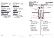
3.4 Line Interfacing<br />
3.4.1 D-Sub Socket<br />
1<br />
2<br />
3<br />
4<br />
5<br />
6<br />
7<br />
8<br />
9<br />
Network Configuration (Hardware)<br />
Tip: Make a basic all-time decision as to which colour<br />
core is to be used for the data lines.<br />
Our recommendation:<br />
CAN_L: red or white (lighter colour)<br />
CAN_H: green or brown (darker colour)<br />
The pin wiring and connector systems of <strong>CANopen</strong> networks<br />
have been defined by the CiA and are also published<br />
by this organisation.<br />
The controllers provided by <strong>Kuhnke</strong> GmbH make use of<br />
two differrent <strong>CANopen</strong> connector systems.<br />
The devices of the ProfiControl 680V series interface with<br />
<strong>CANopen</strong> via the 9-pin D-Sub socket labelled bus2.<br />
Pin Function<br />
1<br />
2 CAN_L<br />
3 CAN_Gnd<br />
4<br />
5<br />
6<br />
7 CAN_H<br />
8<br />
9<br />
Housing Earth<br />
CiA Draft Standard 301<br />
version 3.0<br />
Connect the cable shield to the plug casing.<br />
E 615 GB 25<br />
06.02.2008
Network Configuration (Hardware)<br />
3.4.2 M12 Plug-and-Socket Connector<br />
2<br />
1<br />
5<br />
3<br />
4<br />
Pin Function<br />
1...3 -<br />
4 CAN_H<br />
5 CAN_L<br />
3.5 Bus Termination<br />
CiA Draft Standard 301<br />
version 3.0<br />
Both ends of a <strong>CANopen</strong> network need to carry a terminating<br />
resistor to minimise line reflexion and, consequently,<br />
to improve the safety of data communication.<br />
Terminating resistance: 120Ω / ¼ W<br />
Station 1<br />
CAN_H<br />
120Ω 120Ω<br />
CAN_L<br />
Station n<br />
If you enconter problems when first starting the bus, the<br />
first thing you should do is to measure the resistance<br />
between CAN_L and CAN_H. The resistance should be<br />
approx. 60 Ω. If it is out by too much check whether the<br />
termination resistors have been put in properly.<br />
26 E 615 GB<br />
06.02.2008
Network Configuration (Hardware)<br />
The bus is to be terminated at its last station connected.<br />
This is achieved either by an extra resistor inside the connector<br />
or by a special connector equipped with its own<br />
termination resistor. The latter are commercially available<br />
for the different connector systems.<br />
E 615 GB 27<br />
06.02.2008
Network Configuration (Hardware)<br />
28 E 615 GB<br />
06.02.2008
Network Configuration (Software)<br />
4 Network Configuration (Software)<br />
A <strong>CANopen</strong> network is made up of several network stations<br />
which are to communicate with each other. To be<br />
able to fulfill this task, the network needs to be configured<br />
and the resulting network configuration data need to be<br />
transferred to the master(s) in suitable form.<br />
4.1 Configuration Tool<br />
Tasks<br />
� Define network stations<br />
� Define communication pathways<br />
� Define <strong>CANopen</strong> manager and configuration master<br />
(NMT master)<br />
� Set data transfer rate<br />
Sources of supply<br />
There are various vendors who supply suitable configuration<br />
tools. It is up to you which one you choose as long as<br />
the tool creates a separate DCF file for every station. To<br />
find a list of vendors and dealers go to the CiA home page<br />
(CAN in Automation) at: headquarters@can-cia.org<br />
Refer to chapter 5.1 Project Setup Example to find an<br />
example configuration created with Pro<strong>CANopen</strong>, the<br />
configuration tool supplied by Vector Informatik GmbH.<br />
Transfer of configuration data to the stations<br />
The NMT master's job is to transmit the network configuration<br />
data to the other bus stations when the network is<br />
started. Or rather it does at least transmit these data to<br />
the non-programmable stations such as decentralised<br />
I/Os.<br />
<strong>Kuhnke</strong> provides separate software for the transfer of configuration<br />
data to <strong>Kuhnke</strong> controllers. It is called COBES.<br />
Refer to the next section to find some details about it.<br />
E 615 GB 29<br />
06.02.2008
COBES<br />
4.2 COBES - Configuration Data Interface<br />
Tasks<br />
4.2.1 Installing COBES<br />
� Transfer configuration data to the <strong>Kuhnke</strong> controllers<br />
in the network<br />
� Enter process data objects and operands for status<br />
and emergency messages into the symbol table<br />
� Transfer network management information to NMT<br />
master<br />
COBES is on the "SOFTWARE & INFORMATION" CD-<br />
ROM distributed by <strong>Kuhnke</strong>.<br />
To order COBES<br />
Part number: E 627 D / GB<br />
Medium: CD-ROM<br />
Contents of package: COBES software, EDS files,<br />
bitmaps, instruction manuals<br />
Install COBES by going to the COBES folder and running<br />
the file SETUP contained in it. The software will install itself<br />
fully automatically and will be available when the DCF<br />
file of the configuration tool you use for your projects<br />
needs to be transferred to the <strong>Kuhnke</strong> controllers.<br />
Depending on your configuration tool you may or may not<br />
be able to directly access the COBES interface. For instructions<br />
on this step please refer to the operating instructions<br />
of you <strong>CANopen</strong> configurator.<br />
If you use Pro<strong>CANopen</strong> to configure your network make<br />
sure to copy COBES.exe to folder x:\PCO\EXEC. You will<br />
then be able to directly run the application via the Pro-<br />
<strong>CANopen</strong> environment.<br />
30 E 615 GB<br />
06.02.2008
4.2.2 Using COBES<br />
Network Configuration (Software)<br />
Instead of directly transferring the configuration data to<br />
the control unit COBES enters them into the KUBES project<br />
files.<br />
Therefore, prior to running COBES you should make sure<br />
that the project is actually on your PC.<br />
4.2.2.1 Running COBES via Windows<br />
• Open the program folder you specified during installation<br />
and click on the COBES icon<br />
• Or run Windows Explorer and double-click on file<br />
COBES.EXE<br />
In both cases you will see the following error message<br />
because the Run command did not reference a DCF file:<br />
E 615 GB 31<br />
06.02.2008
COBES<br />
• Click on "Yes"<br />
• Drop down the list next to "Find in:" and select the<br />
folder containing the DCF files for your network<br />
• Double-click on the appropriate file (the name of a<br />
DCF file contains the node number).<br />
• Go to section 4.2.2.2<br />
A faster method is to start COBES as follows:<br />
• Start menu<br />
• Run...<br />
• Enter: "COBES <br />
32 E 615 GB<br />
06.02.2008
• OK<br />
• Go to section 4.2.2.2<br />
4.2.2.2 Selecting a KUBES Project<br />
A dialogue box will pop up:<br />
Network Configuration (Software)<br />
E 615 GB 33<br />
06.02.2008
COBES<br />
• Select a KUBES project:<br />
• and click on OK.<br />
4.2.2.3 COBES Updates the KUBES Files<br />
COBES will load the configuration data from the DCF file<br />
you specified as well as from the DCF files of the stations<br />
connected to the master.<br />
You should make sure that all relevant DCF files are<br />
stored in the same folder.<br />
34 E 615 GB<br />
06.02.2008
4.2.2.4 Further Functions<br />
Network Configuration (Software)<br />
After that COBES will add the configuration data to the<br />
KUBES project and supplement the symbol table. The following<br />
address ranges will be created for Line B (standard):<br />
� Process data objects (CNIxx.yy, CNOxx.yy)<br />
� Status messages (CSOxx.yy)<br />
� Emergency messages (CEOxx.yy).<br />
The first 8 characters of the name defined in the configurator<br />
will be used as the symbol, whereas the remaining<br />
characters will serve as a comment.<br />
The corresponding address ranges, but starting with the<br />
letter D, will be created for Line A.<br />
� Process data objects(DNIxx.yy, DNOxx.yy)<br />
� Status messages (DSOxx.yy)<br />
� Emergency messages (DEOxx.yy).<br />
Click on the following buttons to control further functions:<br />
� Run KUBES<br />
Launches KUBES with the project you selected.<br />
This is a useful function if you wish to modify the project<br />
you selected or create a KUBES project in the<br />
first place, for example.<br />
� Configuration of KUBES project<br />
This function allows you to delete the configuration<br />
stored in a KUBES project so that you can define a<br />
different one.<br />
� Advanced<br />
COBES always generates a header file for C task<br />
programming. Run this function to set the path to this<br />
file.<br />
E 615 GB 35<br />
06.02.2008
COBES<br />
4.2.2.5 Running COBES Directly via the Configurator<br />
Some configuration tools provide a function for directly<br />
starting COBES (� Pro<strong>CANopen</strong> example5.1.8.2). The<br />
prerequisite is that the configuration tool supports popup<br />
menus:<br />
• Right-click on the station<br />
• Select "Export to KUBES"<br />
• Go to section 4.2.2.2<br />
36 E 615 GB<br />
06.02.2008
5 Setting up Projects<br />
Project Setup<br />
Setting up projects would normally include the use of a<br />
configuration tool to create the set of network data. We<br />
produced our example with Pro<strong>CANopen</strong>, a configuration<br />
tool supplied by Vector. However, you can use any other<br />
tool that is capable of creating DCF files.<br />
As an alternative, if you have no such configuration tool,<br />
you can also use the set configuration files available for<br />
<strong>Kuhnke</strong> devices.<br />
E 615 GB 37<br />
06.02.2008
Project Setup<br />
5.1 Project Setup Example<br />
5.1.1 Task Description<br />
PLC1<br />
This tutorial covers the entire process of setting up a<br />
<strong>CANopen</strong> network right down to testing it by means of the<br />
control system connected.<br />
A ProfiControl 680V-C is to communicate with a CanControl<br />
691 I/O via a <strong>CANopen</strong> bus. We will make the minimum<br />
settings required for producing an operative system.<br />
We used Vector's Pro<strong>CANopen</strong> application for configuration.<br />
However, you can use any other tool that is capable<br />
of creating DCF files.<br />
<strong>CANopen</strong><br />
Station 1 Station 2<br />
Unit 680V-C CanControl 691 I/O<br />
Name PLC1 IO2<br />
Device ID 1 2<br />
Function<br />
PLC<br />
<strong>CANopen</strong> manager<br />
Remote I/O<br />
Data<br />
channels<br />
PLC1 � IO2 IO2 � PLC1<br />
38 E 615 GB<br />
06.02.2008<br />
IO2
5.1.2 Start Pro<strong>CANopen</strong><br />
Project Setup<br />
Pro<strong>CANopen</strong> is the configuration tool supplied by Vector<br />
Informatik GmbH.<br />
• In Windows, open the program group into which the<br />
Pro<strong>CANopen</strong> icon was placed during installation.<br />
• Click on the Pro<strong>CANopen</strong> icon to launch the configuration<br />
tool displaying its network editor:<br />
E 615 GB 39<br />
06.02.2008
Project Setup<br />
5.1.3 Create a Project Folder<br />
For safety reasons, please create a project folder at this<br />
early point even though you have no data to store in it yet.<br />
This is the only way to ensure that you can save the configuration<br />
data after every step of setting up your project.<br />
Specify a name that you will later be able to relate to your<br />
KUBES program.<br />
• Select Save as from the File menu. The dialogue<br />
popping up lets you set the path to the project data<br />
files.<br />
Example: c:\pco\E615<br />
• Click on OK to return to the network editor screen.<br />
5.1.4 Define the First Station (PLC1)<br />
• Right-click on the ID ? icon.<br />
• Select Configuration from the popup menu to display<br />
the following dialogue box:<br />
40 E 615 GB<br />
06.02.2008
Project Setup<br />
• Specify a name and station number (node ID) for<br />
Station1:<br />
Name: PLC1<br />
Node ID: 1<br />
Enter a Name that is unique in the entire network. Various<br />
dialogues of the program will address this node by the<br />
name you specify at this point.<br />
The address is the node address(same as the node ID)<br />
as specified by <strong>CANopen</strong>. This address is mandatory because<br />
the software uses it to access the physical unit in<br />
the CAN network. The address, too, is to be unique in the<br />
network.<br />
• Click on the Device Type button to display another<br />
dialogue box.<br />
E 615 GB 41<br />
06.02.2008
Project Setup<br />
The list in this box contains all the device types that you<br />
can choose from. The folders with company names are<br />
containers for the EDS files (Electronic Data Sheet) of the<br />
available devices.<br />
• Click on <strong>Kuhnke</strong>; the panel on the right will display a<br />
list of <strong>Kuhnke</strong>'s <strong>CANopen</strong> devices whose EDS files<br />
have been installed on your PC:<br />
• Double-click on file KU680V.eds<br />
42 E 615 GB<br />
06.02.2008
Project Setup<br />
This will close the "Electronic Data Sheet EDS" window<br />
and refresh the information shown in the "Node<br />
Configuration" dialogue:<br />
All other entries into this dialogue (such as short name, information<br />
etc.) are optional and intended to make for a<br />
clearer topology picture.<br />
• Click on OK to accept and confirm the entries. This<br />
will close the dialogue box. The network editor will<br />
graphically display Station1:<br />
E 615 GB 43<br />
06.02.2008
Project Setup<br />
5.1.5 Define Station 2 (IO2)<br />
• Select New Node from the Edit menu to make the<br />
icon for a new station appear:<br />
• Proceed as described for Station 1 (� 5.1.4). Station<br />
1 and Station 2 differ in their name, address and type<br />
of device:<br />
Name: IO2<br />
Node ID: 2<br />
Type of device: Ku_691_8di8do<br />
The network editor displays this as follows:<br />
44 E 615 GB<br />
06.02.2008
5.1.6 Define the Communication Pathways<br />
Project Setup<br />
You now have to define the communication pathways.<br />
For the purposes of our example we want to set two<br />
channels, i.e. from PLC1 to IO2 and vice versa:<br />
• Right-click on the icon of PLC1, then select<br />
Graphical Connection from the popup menu. A<br />
question mark will appear next to the mouse pointer.<br />
• Click on IO2. The "Graphical Connection" editor will<br />
appear immediately:<br />
• Click on the Insert PDOs button. The following<br />
dialogue is displayed:<br />
E 615 GB 45<br />
06.02.2008
Project Setup<br />
• Change the Prefix item (see highlighted entry<br />
above) into IO2_ to document the allocation to the<br />
I/O unit.<br />
• Confirm by clicking on OK. The Graphical Connection<br />
dialogue shows two new connections:<br />
• Click on OK to finish off this step.<br />
46 E 615 GB<br />
06.02.2008
Project Setup<br />
Two double arrows in the Network Editor tell you about<br />
the connections between the two units:<br />
E 615 GB 47<br />
06.02.2008
Project Setup<br />
5.1.7 Set <strong>CANopen</strong> Options<br />
It takes a couple of basic settings to allow the network to<br />
work properly.<br />
5.1.7.1 Global Configuration<br />
• Select Global Configuration from the Project<br />
menu.<br />
The following dialogue is displayed:<br />
• Fill in the form as illustrated above:<br />
Baud rate 500<br />
Network number 1<br />
<strong>CANopen</strong> manager PLC1<br />
Configuration manager ���� (Station1)<br />
Sync ���� (No)<br />
Vector Pro<strong>CANopen</strong> node ID 127<br />
Network name (optional)<br />
Info (optional)<br />
48 E 615 GB<br />
06.02.2008
Project Setup<br />
Network Name and Info are optional. Anything you enter<br />
into these boxes will be used for printing out and exporting<br />
the project documentation.<br />
• Click on OK to confirm your entries and close the<br />
dialogue box.<br />
5.1.7.2 Define the <strong>CANopen</strong> Manager<br />
• Right-click on the icon of PLC1, then select Device<br />
Access from the popup menu. A dialogue box will be<br />
displayed:<br />
E 615 GB 49<br />
06.02.2008
Project Setup<br />
• Click on tab <strong>CANopen</strong> manager:<br />
• Type in your entries as follows:<br />
Device is NMT master ����<br />
Start all nodes at boot-up ����<br />
50 E 615 GB<br />
06.02.2008
The information in the window will be updated:<br />
• Pick IO2 from the list box<br />
• Then click on the button labelled Change:<br />
• Type in your entries as follows:<br />
Restart Guarding after guard error ����<br />
Set operational after guard error ����<br />
Project Setup<br />
Guard time 100 [ms]<br />
E 615 GB 51<br />
06.02.2008
Project Setup<br />
Retry Factor 2<br />
• Click on OK to confirm.<br />
The window now looks as follows:<br />
• Click on the two buttons labelled Apply to Slaves<br />
and Add to OD. These clicks are mandatory to ensure<br />
that the entries will actually take effect.<br />
• Click on Accept.<br />
• Finally, click on OK to close the dialogue window.<br />
52 E 615 GB<br />
06.02.2008
5.1.8 Transfer the Data to the PLC<br />
Project Setup<br />
The next thing you need to do is to transfer the data to the<br />
configuration master and the <strong>CANopen</strong> manager. In our<br />
case, ProfiControl 680V (PLC1) fulfills both tasks.<br />
If you are working with <strong>Kuhnke</strong> control units running<br />
KUBES programs, you will first of all stay offline to copy<br />
the data files to the KUBES project folders where KUBES<br />
will pick them up to transfer them into the control unit.<br />
Skip chapter "Prepare the KUBES Project" if the KUBES<br />
project for this PLC already exists (5.1.8.1).<br />
5.1.8.1 Prepare the KUBES Project<br />
• Start KUBES<br />
• Create a project for Profi Control 680V and name it<br />
PLC1.<br />
5.1.8.2 Copy the <strong>CANopen</strong> Data to the KUBES Project<br />
• Go back to Pro<strong>CANopen</strong> and load the network project<br />
called PLC1.<br />
• Right-click on the icon of PLC1 and select Export to<br />
KUBES from the menu:<br />
E 615 GB 53<br />
06.02.2008
Project Setup<br />
• Make your selections as illustrated above:<br />
KUBES project, drive C, project PLC1<br />
• Click on OK to confirm.<br />
5.1.8.3 Prepare the Devices<br />
• Answer the prompt with Yes to have the project's<br />
symbol table overwritten.<br />
Following data transfer to the KUBES project the dialogue<br />
box will close automatically.<br />
The PLC now hosts a complete set of <strong>CANopen</strong> data.<br />
• Set the coding switch of Can I/O:<br />
2 = on (node ID 2),<br />
9 = on (500 kbit/s)<br />
• Supply power to the devices.<br />
• Connect the two devices with a CAN cable: bus2 of<br />
ProfiControl 680V with bus in of CanControl 691 I/O.<br />
• Be sure to terminate the bus at both ends (bus termination<br />
resistor in the connector).<br />
54 E 615 GB<br />
06.02.2008
Write a Test Program for the PLC<br />
; Running light for IO2 (PLC1 � IO2)<br />
Project Setup<br />
• Go back to KUBES and load the project called PLC1<br />
• Write the following test program (e.g. in the ORG<br />
module):<br />
L T00.01 ; 100 ms clock marker<br />
= IO2_WRIT CNO00.00 ; (IO2_WriteDigitalOutputBlock1)<br />
; Show IO2 input data at PLC1 outputs<br />
L IO2_READ CNI00.00 ; (IO2_ReadDigitalInputBlock1)<br />
C8T1 SO01.00 ; Outputs SO01.00...07 1<br />
• Transmit the project into the control unit and run it<br />
1 Use the outputs of an output module if your control unit only features 4 slots<br />
E 615 GB 55<br />
06.02.2008
Project Setup<br />
5.1.9 Read the Project Configuration<br />
In KUBES, pick About <strong>CANopen</strong> from the Help menu to<br />
be shown the current <strong>CANopen</strong> configuration of the<br />
KUBES project.<br />
<strong>CANopen</strong> Bus 1<br />
Configuration of <strong>CANopen</strong> Bus 1 if your network has one<br />
(CanControl 691), including station addresses, the baud<br />
rate and names.<br />
<strong>CANopen</strong> Bus 2<br />
Configuration of <strong>CANopen</strong> Bus 2, including station<br />
addresses, the baud rate and names.<br />
The last line of the window displays the path to the configuration<br />
file to be able to retrace your steps to the original<br />
configuration.<br />
56 E 615 GB<br />
06.02.2008
5.1.10 Test the Communication<br />
Project Setup<br />
Look at the status LEDs of the outputs to test if the communication<br />
works.<br />
PLC1<br />
<strong>CANopen</strong><br />
5.1.10.1 Data from PLC1 to IO2<br />
The outputs of CanControl 691 I/O (IO2) output a running<br />
light.<br />
5.1.10.2 Data from IO2 to PLC1<br />
• Connect simultor switches to the inputs of Can I/O<br />
691 (IO2) and supply them with 24 V.<br />
• Switch the inputs on and off.<br />
The outputs set in the program (� Program 5.1.8.3) for<br />
ProfiControl 680V (PLC1) will be actuated accordingly.<br />
E 615 GB 57<br />
06.02.2008<br />
IO2
Project Setup<br />
5.1.11 Monitor the Bus Status via KUBES<br />
Status of stations<br />
(0)...127:<br />
Status of (your<br />
own) <strong>CANopen</strong><br />
kernel<br />
The objective of this exercise is to use the functionality of<br />
KUBES to monitor the network connections and detect<br />
any errors in the <strong>CANopen</strong> manager environment. We will<br />
rely on function Display Address Range which allows<br />
you to monitor up to 256 operands at the same time.<br />
Prerequisites<br />
� The network is still on<br />
� There is communication on the bus<br />
� KUBES is up and running<br />
� Project PLC1 is open<br />
� There is an online connection<br />
� The program has been adjusted<br />
Start the Display Address Range<br />
• Press to open the Display Address Range;<br />
choose operand range CSO...<br />
• Set the Display to Dynamic On:<br />
� You will see the <strong>CANopen</strong> status map.<br />
The messages will be explained on the next couple of<br />
pages.<br />
58 E 615 GB<br />
06.02.2008
5.1.11.1 Analyse Messages<br />
Project Setup<br />
Operands CSO08.08...CSO15.15 (not marked in the<br />
illustration above) are for internal use only and must not<br />
be overwritten by the program.<br />
5.1.11.1.1 Status Map of Stations 1...127<br />
Every one of the operands CSO00.01 to CSO07.15 represents<br />
the status of a specific bus station. The following<br />
messages may appear:<br />
Status Explanation<br />
0 No guarding (monitoring) of this station: the<br />
station has either not been defined or is<br />
unkown to the <strong>CANopen</strong> manager<br />
1 OK! Guarding of station is on<br />
2 Error! Response missing from that station<br />
3 Error! No response from that station and "Life<br />
Time" is out<br />
4 Error! "Toggle" fault<br />
5 Change of status<br />
6 Error! No heartbeat signal form that station<br />
7 Boot-up message received<br />
(network configuration)<br />
8 End of configuration stage; cyclic operation<br />
can be started.<br />
E 615 GB 59<br />
06.02.2008
Project Setup<br />
The current display is:<br />
� Station 2 is being monitored (see circle)<br />
� None of the other stations is being monitored<br />
60 E 615 GB<br />
06.02.2008
Project Setup<br />
5.1.11.1.2 <strong>CANopen</strong> Kernel Status of the <strong>CANopen</strong> Manager<br />
Operands CSO08.00 to CSO08.07 indicate the status of<br />
the <strong>CANopen</strong> kernel. Their output stands for the following:<br />
Operand Bit Value<br />
Explanation<br />
CSO08.00<br />
Kernel status code:<br />
0 0 Channel 1 online<br />
1<br />
1 Channel 1 bus off<br />
0 Channel 1 error active<br />
E 615 GB 61<br />
06.02.2008<br />
1<br />
Channel 1 error passive (error<br />
frames encountered)<br />
2 0 Channel 1 no overrun<br />
1 Channel 1 overrun<br />
3 Not used<br />
4 Not used<br />
5 Not used<br />
6<br />
0 Channel 1 operational<br />
1 Channel 1 not operational<br />
7 Not used<br />
CSO08.01 Own node ID<br />
CSO08.02 Number of emergency frames<br />
CSO08.03 Number of kernel errors<br />
CSO08.04 Baud rate (LB) [kbit/s]<br />
CSO08.05 Baud rate (HB) [kbit/s]<br />
CSO08.06 Config counter (LB)<br />
CSO08.07 Config counter (HB)
Project Setup<br />
The current display is:<br />
� CSO08.00 = 0: Channel 1 online<br />
The bus is on and no error occurred<br />
� CSO08.01 = 1: Own node ID is 1<br />
The station address set in Pro<strong>CANopen</strong><br />
� CSO08.02 = 2: Number of emergency frames<br />
May have been sent during network boot-up. Just<br />
mind that their number no longer increases. In<br />
KUBES, you can run KUBES module CO_MY_R to<br />
read the number of frames (see 6.2.1 Read Emergency<br />
Messages (CO_EMY_R).<br />
� CSO08.03 = 3f: Number of kernel errors<br />
May have occurred during network boot-up. Just<br />
mind that their number no longer increases. In<br />
KUBES, you can run KUBES module CO_MY_R to<br />
read the number of kernel errors (see 6.2.1 Read<br />
Emergency Messages (CO_EMY_R).<br />
� CSO08.04 = Baud rate low byte<br />
CSO08.05 = Baud rate high byte<br />
In this case: 1F4h = 500 kbit/s<br />
62 E 615 GB<br />
06.02.2008
Project Setup<br />
� CSO08.06 = Config counter low byte<br />
CSO08.07 = Config counter high byte<br />
In this case: 0Bh = 11 modifications have been made<br />
so far using the CAN configuration tool.<br />
Operand CSO09.14 indicates the state of the CAN-chip. It<br />
has the following meaning:<br />
Operand Value Bedeutung<br />
CSO09.14 0 CAN-Chip overflow<br />
In case of high traffic on the CAN bus or at a high interrupt exploitation<br />
of the PLC it can come to telegram loss.<br />
This fact is shown by the flag CSO09.14 unequal zero. The flag<br />
can be reset by the PLC programme on zero.<br />
The avoidance of this behaviour can be made by reduction of the<br />
baud rate.<br />
E 615 GB 63<br />
06.02.2008
5.2 Applying the Configuration Data<br />
Project Setup<br />
There are various vendors who supply suitable network<br />
configuration tools. If you possess no such tool you have<br />
the alternative option of using the global configuration provided<br />
by <strong>Kuhnke</strong>.<br />
The relevant folders and files are copied to C:\PCO during<br />
installation of COBES. They apply to <strong>Kuhnke</strong> controllers<br />
and <strong>Kuhnke</strong> I/O modules with a <strong>CANopen</strong> interface only.<br />
5.2.1 Select a Global Configuration File<br />
Refer to the table below to find the global configuration file<br />
matching the target number of stations and the baud rate.<br />
If the number of stations in the network is not the same<br />
as the station number in the table go to the folder with the<br />
next higher number of stations.<br />
Number of stations<br />
(incl. NMT master)<br />
4<br />
8<br />
16<br />
24<br />
32<br />
Baud rate<br />
[kbit/s]<br />
Folder<br />
125 CO_125_4<br />
500 CO_500_4<br />
500 CO_500_8<br />
125 CO_125_8<br />
125 CO_125_16<br />
500 CO_500_16<br />
125 CO_125_24<br />
500 CO_500_24<br />
125 CO_125_32<br />
500 CO_500_32<br />
E 615 GB 65<br />
06.02.2008
Project Setup<br />
5.2.2 Configuration Settings<br />
The table below lists all settings used when creating the<br />
global DCF files. The settings apply to a baud rate of both<br />
125 kbit/s and 500 kbit/s. The heartbeat function is used to<br />
monitor the stations and maintain a small load on the bus<br />
for this function.<br />
Function<br />
4 to 16<br />
stations<br />
Consumer Heartbeat Time [ms] 200 500<br />
Producer Heartbeat Time [ms] 100 250<br />
Configuration manager Station 1<br />
Device is NMT master �<br />
Start all nodes at boot-up �<br />
Restart Guarding after guard error �<br />
Set operational after guard error �<br />
24 to 32<br />
stations<br />
66 E 615 GB<br />
06.02.2008
5.2.3 Export the <strong>CANopen</strong> Data into the KUBES<br />
Project<br />
Project Setup<br />
This section describes how to use the global configuration<br />
files for <strong>Kuhnke</strong> devices in a KUBES project.<br />
Before you start exporting any <strong>CANopen</strong> data to the<br />
KUBES project, make sure that the target KUBES project<br />
already exists on your PC.<br />
• Open the Windows Start menu, locate the COBES<br />
icon in program folder ProfiSoft and click it to run the<br />
application.<br />
The COBES dialogue will be displayed:<br />
• Click on "Browse", find the folder containing the<br />
global configuration files and choose file "D001.DCF"<br />
from it.<br />
E 615 GB 67<br />
06.02.2008
Project Setup<br />
For notes on which folder is to be selected please refer to<br />
section 5.2.1 Select a Global Configuration File.<br />
You will always pick file "D001.DCF" from the folder because<br />
this file contains the configuration for the NMT master.<br />
All other DCF files have been set to <strong>Kuhnke</strong>'s I/O modules.<br />
5.2.4 Select a KUBES Project<br />
• Select a KUBES project:<br />
Refer also to the information provided in section<br />
5.1.8.2 Copy the <strong>CANopen</strong> Data to the KUBES Project<br />
• Click on "OK".<br />
68 E 615 GB<br />
06.02.2008
5.2.5 COBES Updates the KUBES Files<br />
T2: Bus 2<br />
08: Station 08<br />
I0...I3: Input range<br />
Project Setup<br />
COBES will load the configuration data from the DCF file<br />
you specified as well as from the DCF files of the stations<br />
connected to the master.<br />
After that COBES will add the configuration data to the<br />
KUBES project and supplement the symbol table by the<br />
names of the process data objects (CNIxx.yy, CNOxx.yy)<br />
or, for BUS1 (DNIxx.yy, DNOxx.yy), the status messages<br />
(CSOxx.yy) or, for BUS1 (DSOxx.yy) and emergency<br />
messages (CEOxx.yy) or, for BUS1 (DEOxx.yy). The first<br />
8 characters of the name defined in the configurator will<br />
be used as the symbol, whereas the remaining characters<br />
will serve as a comment.<br />
The first 2 characters of the global configurations are indicative<br />
of the bus that the stations have been configured<br />
for. Characters 4 and 5 represent the station number,<br />
whereas characters 7 and 8 represent the station's input<br />
or output range.<br />
Every station configured is made up of 4 inputs and 4 outputs.<br />
This covers all variants of the CanControl 691 I/Oseries<br />
I/O modules which you can therefore use without<br />
having to reconfigure them.<br />
E 615 GB 69<br />
06.02.2008
Project Setup<br />
5.2.6 Applicable Variants of CanControl 691 I/O<br />
� CanControl 691 I/O DI16<br />
16 digital inputs<br />
� CanControl 691 I/O DI8DO8<br />
8 digital inputs, 8 digital outputs<br />
� CanControl 691 I/O DI8DIO8<br />
8 digital inputs plus 8 channels which can be set to<br />
acting either as digital inputs or digital outputs<br />
� CanControl 691 I/O DO24 Sub-D<br />
24 digital outputs for actuating one of <strong>Kuhnke</strong>'s MPPtype<br />
valve islands<br />
70 E 615 GB<br />
06.02.2008
<strong>Kuhnke</strong> Control Units<br />
6 <strong>Kuhnke</strong> Control Units and <strong>CANopen</strong><br />
6.1 Services<br />
The <strong>Kuhnke</strong> devices below currently feature a <strong>CANopen</strong><br />
interface. All of them are programmable logic controllers<br />
(PLCs):<br />
� ProfiControl 680V-C<br />
modular PLC which may also have a PROFIBUS interface<br />
on board<br />
� CanControl 691<br />
PLC with IP65 protection<br />
Special feature: 2 <strong>CANopen</strong> lines<br />
Apart from their usual function as a communicating station<br />
the above controllers can render a couple of further<br />
<strong>CANopen</strong> network services:<br />
6.1.1 Configuration Manager<br />
The <strong>CANopen</strong> manager keeps a binary record of the configuration<br />
data of all network stations.<br />
You can separately say for every station whether or not it<br />
is to be automatically configured at boot-up. This option is<br />
mandatory for all stations that have no separate memory<br />
for configuration data (e.g. remote I/Os such as CanControl<br />
691 I/O 691).<br />
E 615 GB 71<br />
06.02.2008
<strong>Kuhnke</strong> Control Units<br />
6.1.2 NMT Master (NMT = Network Management)<br />
6.1.3 PDO Manager<br />
All services specified in DSP-301 V2.0 (� 8.1.2) are supported.<br />
The access method is a SDO access to the master's<br />
own object dictionary (� 6.1.4). The following services<br />
are available:<br />
� NMT startup<br />
Allows you to define a unit as the master and specify<br />
whether a "Start all Nodes" command is to be sent after<br />
boot-up.<br />
� Slave assignment<br />
Defines which nodes are slaves. Also sets the guarding<br />
options.<br />
� Request NMT<br />
The status of all nodes can be changed individually or<br />
globally (Prepared, Operational, ResetNode, Reset-<br />
Communication, PreOperational).<br />
� Request Guarding<br />
Starts / stops the Guarding service for individual or all<br />
nodes.<br />
Whereas there is basically no limit to the number of PDOs<br />
their maximum number is set by means of a macro. The<br />
granularity of mapping is limited to 8. Consequently, the<br />
Vector software does not support any bit mapping.<br />
72 E 615 GB<br />
06.02.2008
6.1.4 SDO Manager<br />
6.1.5 Sync Manager<br />
<strong>Kuhnke</strong> Control Units<br />
The SDO manager has access to all object dictionaries in<br />
the network including its own. The dictionaries are accessed<br />
with the help of KUBES modules:<br />
� CO_SDOWR<br />
Write object dictionary<br />
� CO_SDORD<br />
Read object dictionary<br />
The SDO manager function must only be provided by the<br />
node that is also the NMT master.<br />
The Sync Manager can be set to act as the sender or recipient<br />
of the Sync object. You can also define the Sync<br />
ID. Further configurable parameters are: "Communication<br />
Cycle Period" and "Synchronous Windows Length". However,<br />
there is no monitoring as to whether all stations respond<br />
within the set time window.<br />
6.1.6 Monitoring Services<br />
The monitoring services are rendered with the help of<br />
KUBES modules in the user program.<br />
E 615 GB 73<br />
06.02.2008
<strong>Kuhnke</strong> Control Units<br />
6.2 KUBES Modules for <strong>CANopen</strong><br />
6.2.1 Read Emergency Messages (CO_EMY_R)<br />
Puts all incoming emergency messages on the error<br />
stack. The error stack stores the 128 most recent<br />
emergency objects in a ring buffer.<br />
KUBES module CO_EMY_R allows you to retrieve the error<br />
messages from the ring buffer for analysis.<br />
Name: ............................................................CO_EMY_R<br />
Controller .......................................................ProfiControl 680V<br />
CanControl 691<br />
Function .........................................................Read emergency messages<br />
Program code:<br />
Parameters:<br />
Input<br />
JPK CO_EMY_R ,<br />
BUS -|¯¯¯¯¯|- DEVICEID<br />
| |- KERN_ERR<br />
|_____|- EMY_ERR<br />
Function Symbol Type<br />
Par00 Selection of bus BUS B1<br />
Output<br />
Range of values<br />
0 � Bus2<br />
1 � Bus1<br />
Function Symbol Type<br />
Range of values<br />
Par01 Station address DEVICEID B8 [1...127]<br />
Par02 Kernel error KERN_ERR B16 See device data<br />
Par03 Emergency error EMY_ERR BX See device data<br />
74 E 615 GB<br />
06.02.2008
<strong>Kuhnke</strong> Control Units<br />
6.2.2 Write Emergency Message (CO_EMY_W)<br />
Run KUBES module CO_EM_W to transmit an emergency<br />
message via the bus. Parameters you need to set<br />
is the bus line and the error number. Every message<br />
transmitted is also added to the error register (index<br />
1001h).<br />
Name: ............................................................CO_EMY_W<br />
Controller .......................................................ProfiControl 680V<br />
CanControl 691<br />
Function .........................................................Write emergency message<br />
Program code:<br />
Parameters:<br />
Input<br />
JPK CO_EMY_W ,<br />
BUS -|¯¯¯¯¯|<br />
EMY_ERR -|_____|<br />
Function Symbol Type<br />
Range of values<br />
Par00 Selection of bus BUS B1<br />
0 � Bus2<br />
1 � Bus1<br />
Par01 Emergency error EMY_ERR BX See device data<br />
E 615 GB 75<br />
06.02.2008
<strong>Kuhnke</strong> Control Units<br />
6.2.3 Read Kernel Error Stack (CO_KSTAT)<br />
The KUBES module described below allows you to read<br />
an error message put on the stack of kernel errors. The<br />
error stacks works like a ring buffer and stores the 64<br />
most recent messages.<br />
Name: ............................................................CO_KSTAT<br />
Controller .......................................................ProfiControl 680V<br />
CanControl 691<br />
Function .........................................................Read kernel error message<br />
Program code:<br />
; JPK CO_KSTAT ,<br />
; BUS -|¯¯¯¯¯|- KERN_ERR<br />
; |_____|<br />
Parameters:<br />
Input<br />
Function Symbol Type<br />
Par00 Selection of bus BUS B1<br />
Output<br />
Range of values<br />
0 � Bus2<br />
1 � Bus1<br />
Function Symbol Type<br />
Range of values<br />
Par01 Kernel error KERN_ERR B16 See device data<br />
76 E 615 GB<br />
06.02.2008
6.2.4 Run NMT Services (CO_NMT)<br />
<strong>Kuhnke</strong> Control Units<br />
The CO_NMT module allows you to execute NMT services<br />
either on one of the bus stations or on the controller<br />
itself. If the station address is set to 128 the NMT service<br />
will be executed on all stations.<br />
The following scope of NMT services is available:<br />
NMT service Parameter value<br />
Enter Prepared 4<br />
Enter Operational 5<br />
Reset Node 6<br />
Reset Communication 7<br />
Enter Preoperational 127<br />
Name: ............................................................CO_NMT<br />
Controller .......................................................ProfiControl 680V<br />
CanControl 691<br />
Function .........................................................Run NMT service<br />
Program code:<br />
JPK CO_NMT ,<br />
BUS -|¯¯¯¯¯|- KERN_ERR<br />
DEVICEID -| |<br />
TRANS_ST -|_____|<br />
E 615 GB 77<br />
06.02.2008
<strong>Kuhnke</strong> Control Units<br />
Parameters:<br />
Input<br />
Function Symbol Type<br />
Range of values<br />
Par00 Selection of bus BUS B1<br />
0 � Bus2<br />
1 � Bus1<br />
Par01 Station address DEVICEID B8 [1...128]<br />
Par02 NMT service TRANS_ST B8 4,5,6,7,127<br />
See table<br />
Output<br />
Function Symbol Type<br />
Range of values<br />
Par03 Kernel error KERN_ERR B16 See device data<br />
78 E 615 GB<br />
06.02.2008
6.2.5 Read Object Dictionary (CO_SDO_R)<br />
<strong>Kuhnke</strong> Control Units<br />
CO_SDO_R lets you read the data of an object dictionary.<br />
Information you have to provide is the target station, the<br />
index and sub-index, and the data volume defined. Index<br />
0 refers to the controller's own object dictionary.<br />
Name: ............................................................CO_SDO_R<br />
Controller .......................................................ProfiControl 680V<br />
CanControl 691<br />
Function .........................................................Read object<br />
dictionary<br />
Program code:<br />
; JPK CO_SDO_R ,<br />
; BUS -|¯¯¯¯¯|- CONFIRMA<br />
; DEVICEID -| |- KERN_ERR<br />
; INDEX -| |- SDO_ERR<br />
; SUB_IND -| |- DATA<br />
; DATA -| |- LNG_DATA<br />
; MAX_DATA -| |<br />
; ENABLE -|_____|<br />
Parameters:<br />
Input<br />
Function Symbol Type<br />
Range of values<br />
Par00 Selection of bus BUS B1<br />
0 � Bus2<br />
1 � Bus1<br />
Par01 Station address DEVICEID B8 [1...127]<br />
Par02 Index INDEX B16 See device data<br />
Par03 Sub-index SUB_IND B8 See device data<br />
Par04 Maximum data volume MAX_DATA B16 See device data<br />
Par05 Enable ENABLE B1<br />
0 � disabled<br />
1 � enabled<br />
E 615 GB 79<br />
06.02.2008
<strong>Kuhnke</strong> Control Units<br />
Output<br />
Function Symbol Type<br />
Range of values<br />
Par06 Confirmation CONFIRMA B1<br />
0 � not confirmed<br />
1 � confirmed<br />
Par07 Kernel error KERN_ERR B16 See device data<br />
Par08 SDO error SDO_ERR BX See device data<br />
Par09 Data DATA BX See device data<br />
Par10 Data volume LNG_DATA B16 See device data<br />
The module is to run with all the parameters remaining<br />
unchanged and Enable = 1 until Confirmation turns 1. The<br />
result will be output until Enable returns to 0 again.<br />
ENABLE<br />
CONFIRMA<br />
While the SDO transfer is being carried out you cannot<br />
run another SDO Write or SDO Read service with different<br />
parameters. If you do you will produce kernel error<br />
KBST_SDO_BUSY (0x80).<br />
SDO transfer will be aborted if Enable turns 0 before a<br />
Confirmation has been received. If you encounter<br />
CIA405_<strong>CANopen</strong>_Kernel_Error = 1 this is indicative of a<br />
SDO error whose error code can be retrieved from the<br />
CIA405_SDO_Error.<br />
80 E 615 GB<br />
06.02.2008
6.2.6 Write Object Dictionary (CO_SDO_W)<br />
<strong>Kuhnke</strong> Control Units<br />
CO_SDO_W lets you write data to an object dictionary. Information<br />
you have to provide is the target station, the index<br />
and sub-index, and the data volume defined. Index 0<br />
refers to the controller's own object dictionary.<br />
Name: ............................................................CO_SDO_W<br />
Controller .......................................................ProfiControl 680V<br />
CanControl 691<br />
Function .........................................................Write object<br />
dictionary<br />
Program code:<br />
; JPK CO_SDO_W ,<br />
; BUS -|¯¯¯¯¯|- CONFIRMA<br />
; DEVICEID -| |- KERN_ERR<br />
; INDEX -| |- SDO_ERR<br />
; SUB_IND -| |<br />
; DATA -| |<br />
; LNG_DATA -| |<br />
; ENABLE -|_____|<br />
Parameters:<br />
Input<br />
Function Symbol Type<br />
Range of values<br />
Par00 Selection of bus BUS B1<br />
0 � Bus2<br />
1 � Bus1<br />
Par01 Station address DEVICEID B8 [1...127]<br />
Par02 Index INDEX B16 See device data<br />
Par03 Sub-index SUB_IND B8 See device data<br />
Par04 Data DATA BX See device data<br />
Par05 Data volume LNG_DATA B16 See device data<br />
Par06 Enable ENABLE B1<br />
0 � disabled<br />
1 � enabled<br />
E 615 GB 81<br />
06.02.2008
<strong>Kuhnke</strong> Control Units<br />
Output<br />
Function Symbol Type<br />
Range of values<br />
Par07 Confirmation CONFIRMA B1<br />
0 � not confirmed<br />
1 � confirmed<br />
Par08 Kernel error KER_ERR B16 See device data<br />
Par09 SDO error SDO_ERR BX See device data<br />
The module is to run with all the parameters remaining<br />
unchanged and Enable = 1 until Confirmation turns 1. The<br />
result will be output until Enable returns to 0 again.<br />
ENABLE<br />
CONFIRMA<br />
While the SDO transfer is being carried out you cannot<br />
run another SDO Write or SDO Read service with different<br />
parameters. If you do you will produce kernel error<br />
KBST_SDO_BUSY (0x80).<br />
SDO transfer will be aborted if Enable turns 0 before a<br />
Confirmation has been received. If you encounter<br />
CIA405_<strong>CANopen</strong>_Kernel_Error = 1 this is indicative of a<br />
SDO error whose error code can be retrieved from the<br />
CIA405_SDO_Error.<br />
82 E 615 GB<br />
06.02.2008
6.2.7 Write Object Dictionary (CO_TRIG)<br />
<strong>Kuhnke</strong> Control Units<br />
Kubes module CO_TRIG puts user-defined data into a<br />
high-priority queue from which it is output to the bus as<br />
quickly as possible.<br />
Name: ............................................................CO_TRIG<br />
Controller .......................................................ProfiControl 680V<br />
CanControl 691<br />
Function .........................................................Write object<br />
dictionary<br />
Program code:<br />
; JPK CO_TRIG ,<br />
; BUS -|¯¯¯¯¯|<br />
; |_____|<br />
Parameters:<br />
Input<br />
Function Symbol Type<br />
Par00 Selection of bus BUS B1<br />
Procedure<br />
Range of values<br />
0 � Bus2<br />
1 � Bus1<br />
Enter the frame to be transmitted into the appropriate<br />
memory range.<br />
Address Explanation<br />
C/D SO10.00 Frame selection byte<br />
C/D SO10.01 Do not use<br />
C/D SO10.02 Frame 0 ID low byte<br />
C/D SO10.03 Frame 0 ID high byte<br />
C/D SO10.04 Do not use<br />
C/D SO10.05 Length of data<br />
C/D SO10.06 Data 1<br />
C/D SO10.07 Data 2<br />
E 615 GB 83<br />
06.02.2008
<strong>Kuhnke</strong> Control Units<br />
C/D SO10.08 Data 3<br />
C/D SO10.09 Data 4<br />
C/D SO10.10 Data 5<br />
C/D SO10.11 Data 6<br />
C/D SO10.12 Data 7<br />
C/D SO10.13 Data 8<br />
C/D SO10.14 Frame 1 ID low byte<br />
C/D SO ........ ......................<br />
C/D SO15.15 Queue capacity usage<br />
(0x19EAFF)<br />
The frame selection (memory range C/D SO10.00) defines<br />
which of the 7 possible frames is to be put in the<br />
queue by running the module:<br />
Bit 0 = 1 => frame 0<br />
Bit 1 = 1 => frame 1<br />
Bit 2 = 1 => frame 2<br />
Bit 3 = 1 => frame 3<br />
Bit 4 = 1 => frame 4<br />
Bit 5 = 1 => frame 5<br />
Bit 6 = 1 => frame 6<br />
Running program module CO_TRIG will put the frame in<br />
the queue from where it will be sent to the bus with high<br />
priority.<br />
The data structure also indicates how much of the queue<br />
capacity has been used. The queue can have up to 7<br />
high-priority frames in it.<br />
84 E 615 GB<br />
06.02.2008
6.3 <strong>CANopen</strong> Manager<br />
<strong>Kuhnke</strong> Control Units<br />
The <strong>CANopen</strong> manager has various specific tasks:<br />
� Configuration manager (optional)<br />
� NMT Master (NMT = Network Management)<br />
� Monitoring services<br />
You can have different bus stations fulfill these tasks if required.<br />
However, to keep things clear, you should have<br />
only one unit act as a <strong>CANopen</strong> Manager.<br />
The <strong>Kuhnke</strong> control units described earlier are all well<br />
suited to fit this purpose. Apart from that, all of these units<br />
can also act like normal network stations without any<br />
management functions.<br />
E 615 GB 85<br />
06.02.2008
<strong>Kuhnke</strong> Control Units<br />
86 E 615 GB<br />
06.02.2008
7 <strong>CANopen</strong> <strong>Basics</strong><br />
7.1 Overview<br />
<strong>CANopen</strong> <strong>Basics</strong><br />
<strong>CANopen</strong> is a network concept (protocol) based on the<br />
CAN protocol defined by Bosch in the middle of the 80s.<br />
The CAN specification describes the framework of data<br />
communication mainly referring to the data security layer,<br />
i.e. the physical data transfer.<br />
CAL, on the other hand, describes the application layer<br />
making powerful communication mechanisms and device<br />
definitions available for high-end process automation.<br />
The <strong>CANopen</strong> network concept combines the serial CAN<br />
bus system and the CAL application layer. <strong>CANopen</strong> also<br />
specifies which service is used to transport which data<br />
type and what significance a data type has for every device<br />
classification. Both definitions together make up the<br />
profile, i.e. the defined interface of every class of devices.<br />
<strong>CANopen</strong> profiles thus describe the specific abilities<br />
and/or parameters of every class of devices. Currently<br />
there are CiA device profiles of digital and/or analogue<br />
I/Os, drives, operating units, sensors and regulators, programmable<br />
controllers and encoders. Further profiles are<br />
under way.<br />
7.2 Data Exchange Methodology<br />
Data exchange via CAN does not address stations but<br />
marks the contents of a message by an identifier that is<br />
unique throughout the network. All stations look at that<br />
identifier to verify whether or not the message is relevant<br />
to them.<br />
Whenever several stations of a <strong>CANopen</strong> network try to<br />
transmit data at the same time, the urgency (or priority) of<br />
the message decides which piece of information is transferred<br />
first.<br />
E 615 GB 87<br />
06.02.2008
<strong>CANopen</strong> <strong>Basics</strong><br />
7.2.1 Bus Allocation by Bit-wise Arbiting<br />
Message A<br />
Message B<br />
Message C<br />
Fast data transfer via a serial bus demands fast bus allocation<br />
mechanisms to decide which one of several parallel<br />
transfer requests is served first. In the case of CAN, the<br />
identifier of a message is the means to provide this<br />
mechanism. The identifier with the lowest number to it has<br />
the highest priority. The priorities are defined by setting<br />
the appropriate binary values at the system design stage;<br />
these values cannot later be changed dynamically.<br />
How bus conflicts are avoided<br />
Conflicts on the bus are avoided by bit-wise arbiting and<br />
the identifiers in that every station monitors the bus signal<br />
level with every bit. The dominant status (0) overwrites the<br />
recessive status (1). All stations transmitting at a recessive<br />
signal level while monitoring the bus at a dominant<br />
level will lose the fight and automatically turn into recipients.<br />
This simple mechanism ensures that the message<br />
with the highest priority will be automatically transferred<br />
across the bus.<br />
Example:<br />
Identifier Data<br />
10 9 8 7 6 5 4 3 2 1 0<br />
Messages A and B will be denied access to the bus because<br />
message C has higher priority (identifier). The relevant<br />
slaves will turn into recipients.<br />
88 E 615 GB<br />
06.02.2008
7.3 <strong>CANopen</strong> Object Dictionary<br />
<strong>CANopen</strong> <strong>Basics</strong><br />
The <strong>CANopen</strong> communication profile is based on an object<br />
dictionary.<br />
Index (hex) Object<br />
0001-001F Simple data types<br />
0020-003F Pre-defined complex data types<br />
0040-005F Vendor-specific complex data types<br />
0060-007F Simple data types specific to a device profile<br />
0080-009F Complex data types specific to a device profile<br />
00A0-0FFF Reserved for extensions<br />
1000-1FFF Range of the communication profile<br />
2000-5FFF Vendor-specific range<br />
6000-9FFF Range of the standardised device profile<br />
A000-FFFF Reserved<br />
The index range from 0001 to 025F is used for the definition<br />
of data types. A differentiation is made between simple<br />
and complex data types as well as data types defined<br />
specifically with regard to vendors or profiles.<br />
The index range from 0100 to 1FFF covers the general<br />
properties of a device as well as all parameters specific to<br />
communication. The specifications for this range are<br />
therefore the same for all <strong>CANopen</strong> units.<br />
The index range from 2000 to 5FFF allows for vendorspecific<br />
options and extensions of the standardised basic<br />
functions.<br />
The index range from 6000 to 9FFF covers all device data<br />
and/or device functions of a standardised class of devices<br />
to meet the demand of open interchangeability of devices.<br />
E 615 GB 89<br />
06.02.2008
<strong>CANopen</strong> <strong>Basics</strong><br />
7.4 Mechanisms of Communication<br />
7.4.1 Service Data Objects (SDO)<br />
Service data objects are used for changes to the object<br />
dictionary and for status requests. The underlying protocol<br />
supports the transfer of any amount of data; large volumes<br />
of data may have to be sent as several CAN messages<br />
(segmentation). The transfer of every SDO will be<br />
confirmed, that is to say, the recipient of a message will<br />
acknowledge that it has received the message.<br />
7.4.2 Process Data Objects (PDO)<br />
Process data objects are the mechanism provided for the<br />
transfer of process data. Every <strong>CANopen</strong> device either<br />
producing or consuming process data therfore has at least<br />
one PDO available to it. The underlying protocol provides<br />
8 data bytes for user process data in every CAN message.<br />
The transfer of PDOs is not confirmed (unacknowledged).<br />
There are various ways of transferring process data:<br />
� Event<br />
An internal event sets off the sending of a PDO. Applicable<br />
events may be the change of signal level of a<br />
digital input or the completion of a time count made<br />
by this unit.<br />
� Request<br />
In this case, another bus station requests the process<br />
data by sending a Remote Transmission Request<br />
message.<br />
� Synchronous<br />
Synchronous transfer means that a bus station sends<br />
synchronisation frames (messages without any data)<br />
that cause a PDO producer to transfer the process<br />
data.<br />
90 E 615 GB<br />
06.02.2008
7.4.3 Network Management (NMT)<br />
<strong>CANopen</strong> <strong>Basics</strong><br />
Every <strong>CANopen</strong> network only has one single NMT master;<br />
all other stations are NMT slaves. The NMT master<br />
controls the slaves and is the only network station that<br />
can actively change the status of the NMT slaves. A slave<br />
can be in one of the following states.<br />
� Initialization<br />
Every unit is in that state after switching on. At that<br />
stage, the device application and the device communication<br />
are initialised. Upon completion, the node will<br />
automatically turn itself Pre-perational.<br />
� Pre-Operational<br />
Every node in this state supports SDO communication.<br />
The node is not capable of PDO communication<br />
and does not transmit any emergency messages either.<br />
� Operational<br />
In that state, the <strong>CANopen</strong> node is ready to operate<br />
and can itself transfer messages (PDOs, emergency<br />
messages).<br />
� Prepared<br />
A node that is "prepared" no longer supports any<br />
network communication, be it PDO or SDO communication.<br />
However, the appropriate network command<br />
(e.g. Start Node) can change the network state of that<br />
node.<br />
E 615 GB 91<br />
06.02.2008
<strong>CANopen</strong> <strong>Basics</strong><br />
7.4.4 Emergency Messages<br />
Whenever a fault or error occurs in a <strong>CANopen</strong> unit, the<br />
device will transmit a high-priority 8-byte alert object<br />
(emergency message). The frame contains a code that<br />
identifies the problem.<br />
Code (hex) Explanation<br />
00xx No error<br />
10xx Undefined type of error<br />
20xx Power error<br />
21xx Power error at input<br />
22xx Power error in unit<br />
23xx Power error at output<br />
30xx Voltage error<br />
31xx Supply voltage<br />
32xx Internal supply voltage<br />
33xx Bad output voltage<br />
40xx Temperature error<br />
41xx Ambient temperature<br />
42xx Device temperature<br />
50xx Hardware problem<br />
60xx Software problem<br />
61xx Internal software problem<br />
62xx User software problem<br />
63xx Bad parameters selected<br />
70xx Add-on modules<br />
80xx Communication<br />
90xx External error<br />
FF00 Device-specific<br />
The table lists a couple of error codes defined in the<br />
communication profile.<br />
92 E 615 GB<br />
06.02.2008
7.4.5 Monitoring of Devices<br />
7.4.5.1 Node Guarding<br />
<strong>CANopen</strong> <strong>Basics</strong><br />
<strong>CANopen</strong> provides two mechanisms to ensure that the<br />
bus stations are fully functional.<br />
This mechanism is controlled by the NMT master to cyclically<br />
check if the NMT slaves are still able to communicate.<br />
It involves the NMT master sending out messages to<br />
the NMT slaves that the slaves must respond to by returning<br />
their communication status within the set timeout. This<br />
enables the NMT master to realise if a unit fails. On the<br />
other hand, a NMT slave realises if the NMT master has<br />
not requested its devices status for longer than its Life<br />
Time.<br />
E 615 GB 93<br />
06.02.2008
<strong>CANopen</strong> <strong>Basics</strong><br />
7.4.5.2 Heartbeat Message<br />
This mechanism involves a node cyclically transmitting a<br />
so-called heartbeat message containing its<br />
communication status. The message can be received by<br />
one or several stations thus enabling them to monitor the<br />
sending station. They will detect a fault if the heartbeat<br />
message is not transmitted.<br />
This mechanism reduces the load on the bus because the<br />
status request message is not required.<br />
7.5 Identifier Distribution<br />
As a rule, communication via a <strong>CANopen</strong> network is<br />
handled by means of identifiers of a length of 11 bit<br />
(standard frames). The so-called pre-defined connection<br />
set sub-divides the available amount of possible identifiers<br />
into various ranges. The identifiers are distributed such<br />
that every <strong>CANopen</strong> network is made up of a maximum of<br />
128 devices: one NMT master and up to 127 NMT slaves.<br />
The 7 low-significant bits of the identifier are used to distinguish<br />
the 127 devices. The remaining 4 bits identify 11<br />
different communication functions.<br />
11-bit identifier (standard frames)<br />
10 9 8 7 6 5 4 3 2 1 0<br />
Function code Device identifier (0, 1-127)<br />
94 E 615 GB<br />
06.02.2008
<strong>CANopen</strong> <strong>Basics</strong><br />
The table below summarises the identifiers allocated in<br />
compliance with the preset matrix of identifiers for the<br />
messages defined.<br />
Communication object<br />
Broadcast<br />
Peer-to-peer messages<br />
Function code COB-ID<br />
dec. bin dec.<br />
NMT commands 0 0000 0<br />
Sync message 1 0001 128<br />
System time 2 0010 256<br />
Alert object 1 0001 128 + device ID<br />
Transmit PDO 1 3 0011 384 + device ID<br />
Receive PDO 1 4 0100 512 + device ID<br />
Transmit PDO 1 5 0101 640 + device ID<br />
Receive PDO 1 6 0110 768 + device ID<br />
Transmit PDO 1 7 0111 896 + device ID<br />
Receive PDO 1 8 1000 1024 + device ID<br />
Transmit PDO 1 9 1001 1152 + device ID<br />
Receive PDO 1 10 1010 1280 + device ID<br />
Transmit SDO 11 1011 1408 + device ID<br />
Receive SDO 12 1100 1536 + device ID<br />
NMT error 14 1110 1792 + device ID<br />
Please note that the synchronisation message has the<br />
highest priority in the system, directly followed by the system<br />
time and the alert messages. The next priority group<br />
is made up of the first Transmit PDO and Receive PDO<br />
frames.<br />
Communication through the SDO channels has a comparatively<br />
low priority.<br />
E 615 GB 95<br />
06.02.2008
<strong>CANopen</strong> <strong>Basics</strong><br />
7.5.1 PDO Mapping<br />
The functionality of a device equipped with a <strong>CANopen</strong> interface<br />
is described by the application object. Application<br />
objects are device parameters that can be either read or<br />
written, including but not limited to input and output values,<br />
speeds or further states.<br />
Every process data object can carry up to 8 bytes. Consequently,<br />
you need to define the positions within a PDO's<br />
data array. This definition or allocation is called a PDO<br />
mapping. It allows you to generate messages containing<br />
specific sets of information of a <strong>CANopen</strong> device. The<br />
communication profile range of the object dictionary contains<br />
the information about the PDO structure so that the<br />
structure is available via the network. If the allocation of<br />
application objects to a process data object permanently<br />
changes you would refer to it as dynamic mapping.<br />
96 E 615 GB<br />
06.02.2008
7.6 Device Description EDS and DCF<br />
<strong>CANopen</strong> <strong>Basics</strong><br />
EDS and DCF are standardised descriptions of <strong>CANopen</strong><br />
devices in the shape of a so-called Electronic Data Sheet<br />
(EDS) or a Device Configuration File (DCF) respectively.<br />
The EDS lists all objects, the baud rates supported, the<br />
manufacturer and many other details. However, the EDS<br />
is only like a template for the unit because the actual values<br />
of an object are not contained in it.<br />
The DCF has the same structure as the EDS plus that it<br />
contains the values of every object.<br />
Both description files imitate the Windows *.ini format<br />
making it easy for users to add new devices to the network:<br />
connect the hardware and upload the EDS or DCF<br />
file to the master. That's all it takes to get the unit ready<br />
for action.<br />
E 615 GB 97<br />
06.02.2008
<strong>CANopen</strong> <strong>Basics</strong><br />
98 E 615 GB<br />
06.02.2008
8 Appendix<br />
8.1 References<br />
8.1.1 <strong>Kuhnke</strong> <strong>Manual</strong>s<br />
Title / Subject Number<br />
Appendix<br />
Programming <strong>Manual</strong> - <strong>Kuhnke</strong> PLC systems E 417 GB<br />
KUBES - Programming software for <strong>Kuhnke</strong>'s PLC systems<br />
E 327 GB<br />
ProfiControl 680V E 598 GB<br />
CanControl 691 E 623 GB<br />
CanControl I/O 691 E 622 GB<br />
CD-ROM Software & Information E 627 D/GB<br />
8.1.2 <strong>CANopen</strong> Specifications (English Only)<br />
Source<br />
CAN in Automation<br />
Am Weichselgarten 26<br />
D-91058 Erlangen<br />
Fax: 0049-9131-69086-79<br />
E-mail: headquarters@can-cia.org<br />
Web: http://www.can-cia.org<br />
Title / Subject Number<br />
Application Layer and Communication Profile DS 301 V4.01<br />
Framework for Programmable <strong>CANopen</strong> Devices DSP 302 V3.0<br />
Device Profile for Generic I/O Modules DS 401 V2.0<br />
Device Profile Drives and Motion Control DSP 402 V1.1<br />
Device Profile Human Machine Interfaces DSP 403 V1.0<br />
Device Profile for IEC 1131 Programmable Devices DSP 405 V1.0<br />
Device Profile for Encoders DSP 406 V2.0<br />
E 615 GB 99<br />
06.02.2008
Appendix<br />
8.2 Abbreviations<br />
CAN Controller Area Network<br />
<strong>CANopen</strong> Controller Area Network of CiA<br />
CiA CAN in Automation - CAN user association<br />
EDS Electronic Data Sheet; technical brief of a unit<br />
DCF Device Configuration File; configuration of a unit<br />
DI Digital Input<br />
DO Digital Output<br />
ID Identifier, unique identification<br />
I/O Input / Output<br />
NMT Network Management<br />
PDO Process Data Objects<br />
SDO Service Data Objects<br />
OV Object dictionary<br />
PDO mapping Copying of process data to the communication range<br />
100 E 615 GB<br />
06.02.2008
8.3 Sales & Service<br />
Sales & Service<br />
Please visit our Internet site to find a comprehensive<br />
overview of our sales and service network including all the<br />
relevant addresses. You are, of course, always welcome<br />
to contact our staff at the main factory in Malente:<br />
8.3.1 Main Factory in Malente<br />
<strong>Kuhnke</strong> Automation GmbH & Co. KG<br />
Lütjenburger Straße 101<br />
23714 Malente<br />
Telefon (0 45 23) 402-0<br />
Telefax (0 45 23) 402 247<br />
E-Mail sales@kuhnke.de<br />
Internet www.kuhnke.de<br />
8.3.2 Customer Service<br />
<strong>Kuhnke</strong> Automation GmbH & Co. KG<br />
Lütjenburger Straße 101<br />
23714 Malente Deutschland<br />
Telefon +49 (0)4523 402 200<br />
E-Mail service@kuhnke.de<br />
Internet www.kuhnke.de<br />
E 615 GB 101<br />
06.02.2008
Appendix<br />
8.4 Index<br />
address ....................................41<br />
attention ...................................12<br />
bus termination ........................26<br />
cable routing and wiring...........19<br />
CAL ..........................................88<br />
<strong>CANopen</strong> ...................................7<br />
network.................................21<br />
<strong>CANopen</strong> manager ..................86<br />
characteristic impedance .........23<br />
CiA .............................................7<br />
COBES ....................................29<br />
conductor resistance................23<br />
danger......................................12<br />
DCF..........................................98<br />
device description ....................98<br />
Device ID .................................38<br />
device monitoring.....................94<br />
dirt ............................................20<br />
D-Sub socket ...........................25<br />
earthed capacitance ................23<br />
EDS..........................................98<br />
electromagnetic compatibility...17<br />
electromagnetic interference ...20<br />
emergency ...............................93<br />
general notes on installation....18<br />
heartbeat..................................95<br />
identifier ...................................95<br />
impact and vibration.................20<br />
inductive actuators...................20<br />
initialization ..............................92<br />
installation................................15<br />
instruction ................................13<br />
interference emission...............18<br />
KUBES modules ......................74<br />
limiting value class...................18<br />
line architecture .......................22<br />
line length ................................23<br />
location of installation ..............19<br />
M12 connector .........................26<br />
maintenance ............................16<br />
material ....................................23<br />
network management ..............92<br />
NMT .........................................92<br />
node address ...........................41<br />
node guarding..........................94<br />
node ID ....................................41<br />
noise immunity.........................17<br />
note..........................................12<br />
notes ........................................12<br />
object dictionary.......................90<br />
operational ...............................92<br />
PDO .........................................91<br />
PDO manager..........................72<br />
PDO mapping ..........................97<br />
pin wiring..................................25<br />
pre-operational.........................92<br />
prepared ..................................92<br />
Pro<strong>CANopen</strong>............................39<br />
process data objects................91<br />
project planning .......................15<br />
reliability...................................11<br />
RS 485.....................................21<br />
102 E 615 GB<br />
06.02.2008
safety .......................................14<br />
SDO .........................................91<br />
SDO manager..........................73<br />
service data objects .................91<br />
servicing...................................16<br />
shield........................................23<br />
shielding...................................24<br />
Index<br />
target group .............................11<br />
temperature .............................19<br />
terminating resistor ..................26<br />
transfer rate .............................23<br />
under construction ...................12<br />
working steps...........................13<br />
E 615 GB 103<br />
06.02.2008