Kuhnke Electronics Instruction Manual
Kuhnke Electronics Instruction Manual
Kuhnke Electronics Instruction Manual

Create successful ePaper yourself
Turn your PDF publications into a flip-book with our unique Google optimized e-Paper software.
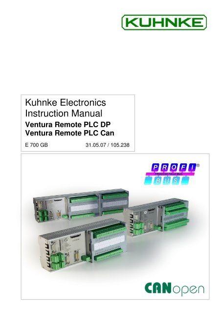
<strong>Kuhnke</strong> <strong>Electronics</strong><br />
<strong>Instruction</strong> <strong>Manual</strong><br />
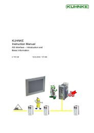
Ventura Remote PLC DP<br />
Ventura Remote PLC Can<br />
E 700 GB 31.05.07 / 105.238
This instruction manual is primarily intended for use by design, project and<br />
development engineers. It does not contain any availability information.<br />
Data is only given to describe the product and must not be regarded as<br />
guaranteed properties in the legal sense. Any claims for damages - on<br />
whatever legal grounds - are excluded except for instances of deliberate<br />
intent or gross negligence on our part.<br />
We reserve the rights for errors, omissions and modifications.<br />
Reproduction even of extracts only with the editor's express and written<br />
prior consent.
Table of Contents<br />
Introduction<br />
1 Introduction ................................................................................................9<br />
1.1 Area of Application .......................................................................10<br />
1.2 Variants ........................................................................................11<br />
1.3 From Stand-alone Controllers to Distributed Networks................12<br />
1.4 Ventura Remote PLC as a Field Bus Unit....................................14<br />
1.5 Network Examples .......................................................................15<br />
1.5.1 PROFIBUS-DP ...........................................................................15<br />
1.5.2 CANopen ....................................................................................16<br />
2 Reliability, Safety .....................................................................................17<br />
2.1 Intended Use ................................................................................17<br />
2.2 Target Group ................................................................................17<br />
2.3 Reliability ......................................................................................17<br />
2.4 Symbols........................................................................................18<br />
2.4.1 Danger........................................................................................18<br />
2.4.2 Attention .....................................................................................18<br />
2.4.3 Note ............................................................................................19<br />
2.4.4 Under Construction.....................................................................19<br />
2.4.5 <strong>Instruction</strong> ...................................................................................19<br />
2.5 Safety ...........................................................................................20<br />
2.5.1 Project Planning and Installation ................................................21<br />
2.5.2 Maintenance and Servicing ........................................................22<br />
2.6 Electromagnetic Compatibility......................................................23<br />
2.6.1 Definition.....................................................................................23<br />
2.6.2 Interference Emission.................................................................23<br />
2.6.3 General Notes on Installation .....................................................23<br />
2.6.4 Electrical Immission Safeguard ..................................................24<br />
2.6.5 Cable Routing and Wiring ..........................................................24<br />
2.6.6 Location of Installation................................................................24<br />
2.6.7 Particular Sources of Interference..............................................25<br />
3 Hardware .................................................................................................27<br />
3.1 System Description ......................................................................27<br />
3.2 Mechanical Design .......................................................................28<br />
3
Introduction<br />
3.2.1 Dimensions.................................................................................28<br />
3.2.2 Installation ..................................................................................30<br />
3.3 Power Supply ...............................................................................31<br />
3.3.1 Earth ...........................................................................................31<br />
3.3.2 Wiring .........................................................................................32<br />
3.3.3 Power Supply .............................................................................33<br />
3.4 Inputs and Outputs .......................................................................35<br />
3.4.1 Digital I/Os, Basic Module ..........................................................35<br />
3.4.2 Digital Combi I/Os.......................................................................37<br />
3.4.3 Analogue Inputs..........................................................................39<br />
3.4.4 Analogue Outputs.......................................................................40<br />
3.5 A, B, Ref Counter .........................................................................41<br />
3.6 Communication Ports ...................................................................42<br />
3.6.1 V.24 / com ..................................................................................42<br />
3.6.2 PROFIBUS .................................................................................43<br />
3.6.3 CAN ............................................................................................44<br />
3.7 Expansion Modules ......................................................................45<br />
3.8 Modes of Operation......................................................................46<br />
3.8.1 External Non-volatile Memory Card (MMC) ...............................46<br />
3.8.2 Mode Selector ............................................................................47<br />
3.8.3 Modes Overview.........................................................................48<br />
3.9 Status and Failure Indication........................................................51<br />
3.10 Memory.........................................................................................52<br />
3.11 Multimedia Card (MMC) ...............................................................52<br />
4 PLC Functions of Ventura Remote PLC..................................................53<br />
4.1 CoDeSys Target Installation.........................................................53<br />
4.2 Writing CoDeSys Programs Online..............................................55<br />
4.2.1 Serial (RS232) Online-V.24........................................................55<br />
4.2.2 CAN: Online CAN.......................................................................57<br />
4.3 Method of PLC Operation.............................................................58<br />
4.3.1 Operating System.......................................................................59<br />
4.3.2 The CoDeSys Runtime System..................................................59<br />
4.3.3 Task Configuration .....................................................................61<br />
4 E 700 GB
Introduction<br />
4.3.4 PLC Configuration ......................................................................65<br />
4.3.5 The User Program ......................................................................68<br />
4.3.6 The Flash File System................................................................69<br />
4.4 Function Library P690.lib/C690.lib ...............................................70<br />
4.4.1 Installing a Thread......................................................................71<br />
4.4.2 Installing / Uninstalling a Timer Task..........................................75<br />
4.4.3 Enabling / Disabling the Outputs ................................................79<br />
4.4.4 Direct Read of Local Inputs ........................................................80<br />
4.4.5 Direct Write of Local Outputs .....................................................81<br />
4.4.6 Installing an Error Module ..........................................................82<br />
4.4.7 Installing an Input IRQ Module ...................................................84<br />
4.4.8 Installing a REF IRQ Module......................................................87<br />
4.4.9 Installing a Reference Value IRQ Module ..................................88<br />
4.4.10 Setting up the Watchdog ..........................................................89<br />
4.5 Library MMC.LIB ..........................................................................91<br />
4.5.1 Procedure ...................................................................................92<br />
4.5.2 Registering with the File System ................................................93<br />
4.5.3 Closing a File..............................................................................94<br />
4.5.4 Copying Files..............................................................................95<br />
4.5.5 Deleting a File.............................................................................96<br />
4.5.6 Determining the Free MMC Space.............................................97<br />
4.5.7 Creating a Subdirectory..............................................................98<br />
4.5.8 Moving a File ..............................................................................99<br />
4.5.9 Opening a File ..........................................................................101<br />
4.5.10 Reading from a File ................................................................103<br />
4.5.11 Renaming a File .....................................................................104<br />
4.5.12 Setting the Edit Bookmark of a File........................................105<br />
4.5.13 Writing to a File.......................................................................106<br />
4.5.14 Initialising the File System......................................................107<br />
4.5.15 Opening, Reading, Closing a File...........................................108<br />
4.5.16 Opening, Writing, Closing a File.............................................110<br />
4.6 PLC States .................................................................................112<br />
4.6.1 RUN..........................................................................................112<br />
5
Introduction<br />
4.6.2 STOP........................................................................................112<br />
4.6.3 Online Reset.............................................................................112<br />
4.6.4 Online Reset (cold)...................................................................113<br />
4.6.5 Reset (original) .........................................................................113<br />
4.7 Programming Using CoDeSys ...................................................114<br />
4.7.1 Variables/Addresses.................................................................114<br />
4.7.2 Variables with Set Addresses...................................................115<br />
4.8 Extraremanent Data ...................................................................117<br />
4.8.1 Remanence Compliant to IEC 11631-3....................................117<br />
4.8.2 Extraremanent Data Range......................................................118<br />
5 Software.................................................................................................125<br />
5.1 The User Program Memory........................................................125<br />
5.2 Programming Using CoDeSys ...................................................126<br />
5.2.1 Overview of I/O Variable Addresses ........................................126<br />
5.3 Special Functions of Internal I/Os ..............................................130<br />
5.3.1 Internal Digital Inputs/Outputs ..................................................130<br />
5.3.2 Functions of Internal Inputs SI_0...SI_3 ...................................132<br />
5.3.3 Functions of Internal Outputs (0.1 A) SO_0...SO_3.................133<br />
5.3.4 Short-circuited Output...............................................................137<br />
5.3.5 Internal Analogue Input Functions............................................139<br />
5.3.6 Internal Analogue Output Functions.........................................141<br />
5.3.7 Functions of Internal Counters .................................................143<br />
5.4 Functions of the Basic Module's Inputs and Outputs .................149<br />
5.4.1 Functions of Inputs SDE_0...SDE_1 (SDE_3) .........................149<br />
5.4.2 Functions of Outputs SDO_0... SD0_1 (SD0_3)......................149<br />
5.5 Start after Configuration Error ....................................................150<br />
5.6 Functions of Expansion Modules 0...3 .......................................150<br />
5.7 Status Messages of Expansion Modules 0...3 ...........................151<br />
6 PROFIBUS-DP ......................................................................................153<br />
6.1 Basic Information........................................................................153<br />
6.1.1 What is PROFIBUS? ................................................................153<br />
6.1.2 Bus Protocol .............................................................................153<br />
6.1.3 Topology...................................................................................153<br />
6 E 700 GB
Introduction<br />
6.1.4 Station Address ........................................................................154<br />
6.1.5 Network Configuration..............................................................154<br />
6.2 Master-Slave Communication ....................................................155<br />
6.2.1 Device Master File KUHN690B.GSD .......................................155<br />
6.2.2 Receive Parameter Data (Prm_Data) .....................................157<br />
6.2.3 Send Diagnostic Data (Diag_Data) ..........................................160<br />
6.2.4 Master-Slave Data Communication..........................................165<br />
7 CANopen ...............................................................................................169<br />
7.1 CANopen for Beginners .............................................................169<br />
7.1.1 CANopen Example...................................................................171<br />
7.1.2 CAN Network Status.................................................................173<br />
8 PLC Error Handling................................................................................177<br />
8.1 "Failure" LED..............................................................................177<br />
8.2 Status Variable "SYSTEMINFO"................................................177<br />
8.3 Faults and Failures Overview.....................................................180<br />
8.3.1 Short-circuited Output (Error #1) ..............................................181<br />
8.3.2 Low Voltage (Power Supply, Error #2).....................................182<br />
8.3.3 Watchdog (Program Runtime Exceeded, Error #3) .................184<br />
9 Appendix................................................................................................185<br />
9.1 Technical Data ...........................................................................185<br />
9.1.1 Basic Data ................................................................................185<br />
9.1.2 Integrated Inputs and Outputs..................................................186<br />
9.1.3 Communication Ports ...............................................................189<br />
9.1.4 Hardware ..................................................................................189<br />
9.1.5 Project Setup ............................................................................190<br />
9.1.6 Permits .....................................................................................190<br />
9.2 Order Specifications ...................................................................191<br />
9.2.1 Controllers Ventura Remote PLC.............................................191<br />
9.2.2 Accessories ..............................................................................191<br />
9.3 Ventura Remote I/O Expansion Modules...................................193<br />
9.4 References .................................................................................194<br />
9.5 Sales & Service ..........................................................................195<br />
9.5.1 Main Factory in Malente ...........................................................195<br />
7
Introduction<br />
9.5.2 Sales Germany.........................................................................195<br />
9.5.3 Customer Service.....................................................................195<br />
9.6 Index...........................................................................................197<br />
8 E 700 GB
1 Introduction<br />
Introduction<br />
Ventura Remote PLC, <strong>Kuhnke</strong>'s compact control system,<br />
has been designed for automation tasks of an average<br />
degree of complexity. As part of a PROFIBUS or<br />
CANopen network it lets you implement decentralised<br />
structures.<br />
Its integrated analogue and digital inputs and outputs with<br />
special functions allow you to process all signals<br />
immediately in the control unit without having to install any<br />
additional devices or modules. The A/B/Ref counter input<br />
provides solutions for drive, positioning and fast counting<br />
tasks.<br />
Ventura Remote PLC can be extended by the modules of<br />
the Ventura Remote I/O system which provide a<br />
convenient means of adapting the unit to your very needs.<br />
CoDeSys, the convenient IEC 61131-3-standard<br />
programming and startup environment, is used for writing<br />
and editing programs in the IL, LD, FD, SFC, CFC and<br />
Structured Text languages.<br />
The PLC's multi-tasking system lets timers or events take<br />
control of parts of the program. A powerful processor very<br />
much speeds up program execution.<br />
Benefits<br />
� Integrated analogue/digital inputs and outputs<br />
� Extendable by modules of system<br />
Ventura Remote I/O<br />
� Event handling by interrupt routines<br />
� User program back-ups on MultiMediaCard<br />
� Extended data memory by MultiMediaCard<br />
� Integrated PROFIBUS DP or CANopen field bus<br />
interface<br />
� DIN top hat rail bracket for easy installation<br />
� CoDeSys version 02.03.05.00 or higher for easy<br />
configuration and programming<br />
� Extensive diagnosis options<br />
9
Introduction<br />
1.1 Area of Application<br />
This instruction manual describes the properties of the<br />
following standard device variants programmable using<br />
CoDeSys:<br />
Ventura Remote PLC DP 16DI/16DO<br />
plus PROFIBUS DP field bus interface ..........................693.9x3.22.00<br />
Ventura Remote PLC CAN 16DI/16DO<br />
plus CANopen field bus interface ....................................693.9x1.22.00<br />
Ventura Remote PLC DP 32DI/32DO<br />
plus PROFIBUS DP field bus interface ..........................693.9x3.44.00<br />
Ventura Remote PLC CAN 32DI/32DO<br />
plus CANopen field bus interface ....................................693.9x1.44.00<br />
x=1: Spring-type locking<br />
x=2: Screw-type locking<br />
The following standard variants are programmed using<br />
KUBES and are thus described in instruction manual E<br />
633:<br />
ProfiControl 690PLC+ 16DI/16DO<br />
plus PROFIBUS DP field bus interface ...........................690.723.22.01<br />
CanControl 690PLC+ 16DI/16DO<br />
plus CANopen field bus interface ....................................690.721.22.01<br />
ProfiControl 690PLC+ 32DI/32DO<br />
plus PROFIBUS DP field bus interface ...........................690.723.44.00<br />
CanControl 690PLC+ 32DI/32DO<br />
plus CANopen field bus interface ....................................690.721.44.00<br />
The following release1 variants are programmed using<br />
KUBES and are thus described in instruction manual E<br />
559:<br />
ProfiControl 690PLC+ 16DI/16DO<br />
plus PROFIBUS DP field bus interface ...........................690.723.22.00<br />
CanControl 690PLC+ 16DI/16DO<br />
plus CANopen field bus interface ....................................690.721.22.00<br />
10 E 700 GB
1.2 Variants<br />
Introduction<br />
Compact controller Ventura Remote PLC has two model<br />
variants which are distinguished by the target field bus:<br />
� Ventura Remote PLC CAN<br />
Field bus: CANopen<br />
� Ventura Remote PLC DP<br />
Field bus: PROFIBUS-DP (as DP slave)<br />
The information below describes the sets of inputs and<br />
outputs of every variant.<br />
Example:<br />
� Ventura Remote PLC CAN 16DI/16DO<br />
Field bus: CANopen<br />
digital inputs: 16<br />
digital outputs: 16<br />
Terminology<br />
This instruction manual specifies the variants as follows:<br />
� Ventura Remote PLC<br />
information referring to all variants,<br />
� Ventura Remote PLC CAN<br />
information referring to variants equipped with a<br />
CANopen interface only,<br />
� Ventura Remote PLC DP<br />
information referring to variants equipped with a<br />
PROFIBUS-DP interface only.<br />
11
Introduction<br />
1.3 From Stand-alone Controllers to<br />
Distributed Networks<br />
For mainly three reasons, programmable logic controllers<br />
and PCs play a key role in industrial automation:<br />
� they are universally applicable,<br />
� programming them is both simple and clear,<br />
� extensive utilities for testing and commissioning are<br />
available.<br />
Standard programming utilities compliant to EN 61131-3<br />
further reduces the effort to be put into programming. The<br />
latest generation of <strong>Kuhnke</strong> PLCs therefore deploys<br />
CoDeSys for programming.<br />
The PLC has become a universal automation tool in a<br />
wide range of application requirements.<br />
Networkable control systems have emerged in response<br />
to the ever increasing requirements of the complexity and<br />
flexibility of machines and process control systems. The<br />
"old" allround PLC for all aspects is being replaced with a<br />
notion of task separation. Every part system just does<br />
what it can do best.<br />
For example, PCs are the perfect tool for computing and<br />
managing large volumes of data at the control level or for<br />
visualisation and operation.<br />
PLCs are responsible for real-time control tasks and, if a<br />
suitable field bus is available, for the process interfacing<br />
level.<br />
The process signals go through remote I/O units located<br />
somewhere near the sensors and actuators.<br />
The field bus focusses on the speed and reliability of data<br />
transfer and the design as an open system. PROFIBUS-<br />
DP and CANopen currently have the greatest market<br />
awareness.<br />
12 E 700 GB
Advantages of Decentralisation<br />
Introduction<br />
� no more multicore cables,<br />
- material (cables, connectors...)<br />
- space (ducts, terminal boxes, switching cabinets)<br />
- installation (time, possible mistakes)<br />
� improved functionality<br />
� clearer arrangements<br />
� reduced setup and commissioning times<br />
� failure response and availability (if one part fails,<br />
other parts continue to work)<br />
� pre-testing of individual stations<br />
� vendor-independence<br />
To be able to fully benefit from these plus points,<br />
standardised solutions for all sub-systems should be<br />
available focussing on the speed and reliability of data<br />
transfer and the design as an open system.<br />
The networkability of Ventura Remote PLC and Ventura<br />
Remote I/O turn the Ventura range into a system that fully<br />
meets the above requirements.<br />
13
Introduction<br />
1.4 Ventura Remote PLC as a Field Bus Unit<br />
The purpose of PLCs is to control machines, facilities etc.<br />
To fulfil its task, it needs to exchange data with the<br />
process controlled which it normally does via inputs and<br />
outputs.<br />
Ventura Remote PLC is a standalone controller<br />
programmed using CoDeSys and equipped with local<br />
digital and analogue I/Os and an incremental encoder<br />
input. Install any of the modules from the Ventura Remote<br />
I/O system to expand its possibilities.<br />
Ventura Remote PLC has the added capability of<br />
exchanging data via PROFIBUS-DP and CANopen which<br />
makes it an intelligent I/O unit for use in PROFIBUS or<br />
CANopen networks.<br />
� Time-critical processes can be controlled without<br />
delays caused by field bus communication.<br />
� Distributed intelligence relieves the master controller<br />
and improves the performance and flexibility of the<br />
machine.<br />
14 E 700 GB
1.5 Network Examples<br />
1.5.1 PROFIBUS-DP<br />
Introduction<br />
PC Control 645-12M-PCI-CoDeSys, the PROFIBUS PLC<br />
in the PC, configured as DP master in a network with DP<br />
slaves.<br />
PC Control 645-12M-PCI<br />
PROFIBUS DP<br />
Ventura DriveControl Ventura other<br />
Remote PLC DP 684DP Remote I/O slaves<br />
Fig.: 1 PC Control 645-12M-PCI-CoDeSys as the DP master<br />
15
Introduction<br />
1.5.2 CANopen<br />
ProfiControl 680V-C as the CANopen configuration<br />
master (top) in a network with Remote Control CAN.<br />
Ventura DriveControl 684 CanControl 691 I/O<br />
Remote PLC CAN<br />
CANopen<br />
ProfiControl 680V-C<br />
Fig.: 2 Ventura Remote PLC CAN in a CANopen network<br />
16 E 700 GB
2 Reliability, Safety<br />
2.1 Intended Use<br />
2.2 Target Group<br />
2.3 Reliability<br />
Reliability, Safety<br />
<strong>Kuhnke</strong> products are designed as resources for use in<br />
industrial environments.<br />
All other applications need to be discussed with the<br />
factory first. The manufacturer shall neither be liable for<br />
any other than the intended use of our products nor for<br />
any ensuing damages. The risk shall be borne by the<br />
operator alone. The use as intended includes that you<br />
read and apply all information and instructions contained<br />
in this manual.<br />
This instruction manual contains all information necessary<br />
for the use of the described product (control device,<br />
control terminal, software, etc.) according to instructions.<br />
It is written for design, project planning, servicing and<br />
commissioning experts. For proper understanding and<br />
error-free application of technical descriptions, instructions<br />
for use and particularly of notes of danger and warning,<br />
extensive knowledge of automation technology is<br />
compulsory.<br />
Reliability of <strong>Kuhnke</strong> controllers is brought to the highest<br />
possible standards by extensive and cost-effective means<br />
in their design and manufacture.<br />
These include:<br />
� selecting high-quality components,<br />
� quality agreements with our suppliers,<br />
� actions to avoid static charges when handling MOS<br />
circuits,<br />
� worst case planning and design of all circuits,<br />
17
Reliability, Safety<br />
2.4 Symbols<br />
2.4.1 Danger<br />
2.4.2 Attention<br />
� visual inspections at various stages of fabrication,<br />
� computer-aided tests of all assemblies and their<br />
interaction in the circuit,<br />
� statistical assessment of the quality of fabrication and<br />
of all returned goods for the immediate taking of<br />
appropriate corrective actions.<br />
Despite the measures described in chapter 2.3 the<br />
occurrence of faults or errors in electronic control units -<br />
even if most highly improbable - must be taken into<br />
consideration.<br />
Please pay particular attention to the additional notices<br />
which we have marked by symbols throughout this<br />
instruction manual. While some of these notices make you<br />
aware of possible dangers, others are intended as a<br />
means of orientation. They are described further down<br />
below in descending order of importance.<br />
This symbol warns you of dangers which may cause<br />
death or grievous bodily harm if operators fail to<br />
implement the precautions described.<br />
This symbol draws your attention to information you must<br />
take a look at to avoid malfunctions, possible material<br />
damage or dangerous states.<br />
18 E 700 GB
2.4.3 Note<br />
Reliability, Safety<br />
This symbol draws your attention to additional information<br />
concerning the use of the described product. This may<br />
include cross references to information found elsewhere<br />
(e.g. in other manuals).<br />
2.4.4 Under Construction<br />
2.4.5 <strong>Instruction</strong><br />
This symbol tells you that the function described was not<br />
or not fully available at the time this document went to<br />
press.<br />
Wherever you see these symbols in the left margin, you<br />
will find a list of steps instructing you to take the<br />
appropriate computer or hardware actions.<br />
They are intended as a means of orientation wherever<br />
working steps and background information alternate (e.g.<br />
in tutorials).<br />
19
Reliability, Safety<br />
2.5 Safety<br />
Our products normally become part of larger systems or<br />
installations. The information below is intended to help<br />
you integrate the product into its environment without<br />
dangers to humans or material/equipment.<br />
To achieve a high degree of conceptual safety in<br />
planning and installing an electronic controller, it is<br />
essential to exactly follow the instructions given in the<br />
manual because wrong handling could lead to rendering<br />
measures against dangers ineffective or to creating<br />
additional dangers.<br />
20 E 700 GB
2.5.1 Project Planning and Installation<br />
Reliability, Safety<br />
� 24 VDC power supply: generate as electrically safely<br />
separated low voltage. Suitable devices are, for<br />
example, split transformers constructed in<br />
compliance with European Standard EN 60742<br />
(corresponds to VDE 0551).<br />
� Power breakdowns or power fades: the program<br />
structure is to ensure that a defined state at restart<br />
excludes all dangerous states.<br />
� Emergency switch-off installations must comply with<br />
EN 60204/IEC 204 (VDE 0113). They must be<br />
effective at any time.<br />
� Safety and precautions regulations for qualified<br />
applications have to be complied with.<br />
� Please pay particular attention to the notices of<br />
warning which, at relevant places, will make you<br />
aware of possible sources of dangerous mistakes or<br />
faults.<br />
� Relevant standards and VDE regulations are to be<br />
complied with in every case.<br />
� Control elements are to be installed in such a way as<br />
to exclude unintended operation.<br />
� Control cables are to be laid in such a way as to<br />
exclude interference (inductive or capacitive) which<br />
could influence controller operation or its functionality.<br />
21
Reliability, Safety<br />
2.5.2 Maintenance and Servicing<br />
� Precautions regulation VBG 4.0 must be observed<br />
when measuring or checking a controller in a powerup<br />
condition. This applies to section 8 (Admissible<br />
deviations when working on parts) in particular.<br />
� Repairs must be carried out by specially trained<br />
<strong>Kuhnke</strong> staff only (usually in the main factory in<br />
Malente). Warranty expires in every other case.<br />
� Only use parts approved of by <strong>Kuhnke</strong>. Only genuine<br />
<strong>Kuhnke</strong> modules must be used in modular<br />
controllers.<br />
� Modular systems: always plug or unplug modules in a<br />
power-down state. You might otherwise damage the<br />
modules or (possibly not immediately recognisably!)<br />
inhibit their functionality.<br />
� Always dispose of any batteries and accumulators as<br />
hazardous waste.<br />
22 E 700 GB
2.6 Electromagnetic Compatibility<br />
2.6.1 Definition<br />
Reliability, Safety<br />
Electromagnetic compatibility is the ability of a device to<br />
function satisfactorily in its electromagnetic environment<br />
without itself causing any electromagnetic interference<br />
that would be intolerable to other devices in this<br />
environment.<br />
Of all known phenomena of electromagnetic noise, only a<br />
certain range occurs at the location of a given device. It is<br />
defined in the relevant product standards.<br />
The design and immunity to interference of programmable<br />
logic controllers are internationally governed by standard<br />
IEC 61131-2 which, in Europe, has been the basis for<br />
European Standard<br />
EN 61131-2.<br />
2.6.2 Interference Emission<br />
Interfering emission of electromagnetic fields, HF<br />
compliant to EN 55011, limiting value class A, Group 1<br />
(industrial use)<br />
If the controller is designed for use in residential areas,<br />
high-frequency emissions must comply with limiting value<br />
class B as described in EN 55011.<br />
Fitting the controller into earthed metal cabinets and installing<br />
filters in the supply lines may produce a shielding<br />
compliant to the above standard.<br />
2.6.3 General Notes on Installation<br />
As component parts of machines, facilities and systems,<br />
electronic control systems must comply with valid rules<br />
and regulations, depending on their field of application.<br />
General requirements concerning the electrical equipment<br />
of machines and aiming at the safety of these machines<br />
23
Reliability, Safety<br />
are contained in Part 1 of European Standard EN 60204<br />
(corresponds to VDE 0113).<br />
For safe installation of our control system please observe<br />
the information contained in the next chapters (� 2.6.4<br />
ff).<br />
2.6.4 Electrical Immission Safeguard<br />
Connect the control system to the protective earth<br />
conductor to eliminate electromagnetic interference.<br />
Practice best cable routing.<br />
2.6.5 Cable Routing and Wiring<br />
Keep power circuits separate from control circuits:<br />
� DC voltages 60 V ... 400 V<br />
� AC voltages 25 V ... 400 V<br />
Joint laying of control circuits is allowed for:<br />
� shielded data signals<br />
� shielded analogue signals<br />
� unshielded digital I/O lines<br />
� unshielded DC voltages < 60 V<br />
� unshielded AC voltages < 25 V<br />
2.6.6 Location of Installation<br />
2.6.6.1 Temperature<br />
Ensure that temperatures, contaminations, impact,<br />
vibration or electromagnetic interference are no<br />
impediment to the installation.<br />
Consider heat sources such as general heating of rooms,<br />
sunlight, heat accumulation in assembly rooms or control<br />
cabinets.<br />
24 E 700 GB
2.6.6.2 Contamination<br />
Reliability, Safety<br />
Use suitable casings to avoid possible negative influences<br />
due to humidity, corrosive gas, liquid or conducting dust.<br />
2.6.6.3 Impact and Vibration<br />
Consider possible influences caused by motors,<br />
compressors, transfer lines, presses, ramming machines<br />
and vehicles.<br />
2.6.6.4 Electromagnetic Interference<br />
Consider electromagnetic interference from various local<br />
sources: motors, switching devices, switching thyristors,<br />
radio-controlled devices, welding equipment, arcing,<br />
switched-mode power supplies, converters / inverters.<br />
2.6.7 Particular Sources of Interference<br />
2.6.7.1 Inductive Actuators<br />
Switching off inductances (such as from relays,<br />
contactors, solenoids or switching magnets) produces<br />
surge voltages. It is mandatory to throttle these noise<br />
voltages to an admissible dimension.<br />
Throttling elements could be diodes, Z diodes, varistors or<br />
RC elements. To find the best adapted elements, we<br />
recommend that you contact the manufacturer or supplier<br />
of the corresponding actuators for the relevant<br />
information.<br />
25
Reliability, Safety<br />
26 E 700 GB
3 Hardware<br />
3.1 System Description<br />
Hardware<br />
Ventura Remote PLC DP is a decentralised input/output<br />
unit (I/O) featuring a 12 Mbps PROFIBUS-DP slave port.<br />
Ventura Remote PLC DP is a decentralised input/output<br />
unit (I/O) featuring a 1 Mbps CANopen port.<br />
The system is made up of various components which you<br />
can combine as necessary.<br />
Adding I/O modules of the Ventura Remote I/O system<br />
expands the capabilities of the basic unit.<br />
See page 193: Ventura Remote I/O Expansion Modules<br />
The following are the maximum configurations:<br />
Basic 16di/16do module<br />
basic modulemodule0 module1 module2 module3<br />
Basic 32di/32do module<br />
basic module module0 module1 module2 module3<br />
27
Hardware<br />
3.2 Mechanical Design<br />
H<br />
W<br />
The housing mainly consists of a backbone of profiled<br />
aluminium with an integrated snap-on device for<br />
installation on a mounting rail. The sides of galvanised<br />
steel sheet are riveted to that backbone.<br />
Fig.: 3 16di/16do variant<br />
3.2.1 Dimensions<br />
Variant 16di/16do 32di/32do<br />
Length "L" [mm] 213 329<br />
Width "W" [mm] 90 90<br />
Height "H" [mm] 75 75<br />
28 E 700 GB<br />
L
Hardware<br />
Extensions<br />
Ventura Remote PLC can be extended by up to four I/O<br />
expansion modules of the Ventura Remote I/O range of<br />
system products. Every expansion module is 112 mm<br />
long.<br />
See page 193: Ventura Remote I/O Expansion Modules<br />
29
Hardware<br />
3.2.2 Installation<br />
Both the Ventura Remote PLC controller and its I/O addons<br />
install on mounting rails (to DIN EN 50022, 35 x 7.5<br />
mm).<br />
Procedure<br />
1.<br />
Push up the device against<br />
the mounting rail from<br />
below, allowing the metal<br />
spring to snap in between<br />
mounting rail and<br />
mounting area. Do as<br />
shown in the illustration.<br />
2.<br />
metal spring<br />
Push the device against<br />
the mounting wall until is<br />
snaps in.<br />
Every expansion module installs to the right of the control<br />
unit as described above. Look down the left side of your<br />
expansion module to discover a short ribbon cable and<br />
plug. The connector plugs into the counterplug located<br />
under the lid of the preceding device. There is a recess in<br />
the side wall that the ribbon cable threads through.<br />
30 E 700 GB
3.3 Power Supply<br />
3.3.1 Earth<br />
left side wall<br />
Hardware<br />
The metal housing has to be connected to earth. Use the<br />
earth conductor located on the left side wall.<br />
� Earth conductor<br />
Cross section: min. 2.5 mm²<br />
Length: as short as possible<br />
� Interfacing<br />
Flat plug 6.3 x 0.8 mm<br />
� Function<br />
The earth conductor serves as operative earth<br />
(special case: relay module � E 409 GB).<br />
The +24 VDC and 0 V power supply connectors have<br />
an internal (by spring-actuated contacts on the PCB)<br />
capacitive connection to the housing which also<br />
attaches them to earth. Line-conducted HF<br />
interference is bled off into the ground.<br />
The PROFIBUS plug connector housing directly<br />
connects to operative earth which is where the cable<br />
shield is attached also.<br />
This earth conductor is no protection against high contact<br />
voltage. To provide sufficient protection, supply the<br />
devices with properly separated low voltage.<br />
31
Hardware<br />
3.3.2 Wiring<br />
All plug-type terminals accept flexible wires whose<br />
conductor has a diameter of 2.5 mm 2 .<br />
Screwdriver<br />
To fit the wires you need a standard flat-blade screwdriver<br />
with a blade max. 4 mm wide.<br />
To unplug<br />
The connectors fit very tightly to avoid them coming off if<br />
exposed to vibration. In case they won't come off by hand<br />
you can use a lever, e.g. a flat object such as a<br />
screwdriver with a wide blade.<br />
Do not pull the lead to unplug. They might otherwise slip<br />
out of the terminals or rip off.<br />
32 E 700 GB
3.3.3 Power Supply<br />
Hardware<br />
Voltages are fed into the unit through screw-type locking<br />
connectors.<br />
Voltage: 24 VDC +25 % /-20 %<br />
System I/Os and special I/Os receive their power through<br />
connector L1. Plug L2 is used to separately attach the<br />
digital I/Os to the voltage supply.<br />
Provide a separate power source for all expansion<br />
modules.<br />
digital I/Os<br />
system I/Os and special I/Os<br />
Keeping the power supply separate allows you to turn off<br />
the outputs without turning off the PLC at the same time.<br />
The advantage is that the system is still supplied with<br />
energy, inputs are kept being read, and communication<br />
(bus, terminal...) is not interrupted.<br />
33
Hardware<br />
3.3.3.1 Power Supply Information<br />
Power to system I/Os and special I/Os<br />
An external source supplies the unit with 24 VDC which a<br />
built-in power supply unit takes to generate the internal<br />
system voltage (5 V) and fed it to the CPU, the device bus<br />
and the fieldbus interfaces.<br />
Please note: always connect the 0V line first and<br />
disconnect it last. You may otherwise experience<br />
equalisation currents go through a V.24 (RS 232)<br />
interface that may be connected. This in turn will cause<br />
the electronic fuse to trip. It will afterwards take about one<br />
minute until the unit has cooled down and is ready to<br />
operate again.<br />
Power to digital I/Os<br />
Power supply to auxiliary push-buttons or other switching<br />
devices that are connected in parallel with the outputs<br />
must also be switched off together with the outputs.<br />
Avoid any reverse feeding of outputs while the power<br />
supply to the outputs is turned off!<br />
This applies if the system is still supplied with power.<br />
Outputs enabled by the user program may be supplied<br />
power via the protective diode of a reversely fed output,<br />
thus overriding the switch-off function of these outputs.<br />
Moreover, the protective diode of the feeding outputs may<br />
yield under high loads and be destroyed.<br />
34 E 700 GB
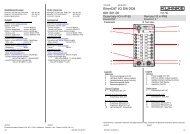
3.4 Inputs and Outputs<br />
3.4.1 Digital I/Os, Basic Module<br />
3.4.1.1 Terminals<br />
3.4.1.2 Electrical Insulation<br />
Hardware<br />
Ventura Remote PLC has a basic module equipped with<br />
16 or 32 digital inputs and 16 or 32 digital outputs.<br />
Digital inputs, 24 VDC<br />
� "0"..."7" inputs 0...7 (16...23) 1<br />
� ".0"...".7" inputs 8...15 (24...31) 1<br />
Digital outputs, 24 VDC, 0.5A<br />
� "0"..."7" outputs 0...7 (16...23) 1<br />
� ".0"...".7" outputs 8...15 (24...31) 1<br />
Inputs and output are not electrically insulated from the<br />
system voltage "L1".<br />
At the time of installation, please take heed of the<br />
information about how to connect the supply voltage (�<br />
3.3.3.1).<br />
1 Variants featuring 32 digital inputs and 32 digital outputs<br />
35
Hardware<br />
3.4.1.3 Inputs<br />
3.4.1.4 Outputs<br />
Inputs are actuated by +24 VDC signals. The 0 V potential<br />
connects to terminal L2-. Whenever an input signal is sent<br />
to the terminal the LED assigned to that terminal will light<br />
up green.<br />
Power (24 VDC) to the outputs is supplied via terminals<br />
"L2+" and "L2-". Whenever an output signal is sent to the<br />
terminal the LED assigned to that terminal will light up red.<br />
Output current<br />
The current of every output is rated at 0.5 A. Outputs are<br />
put into groups of 4 (0...3 and 4...7) which are actuated by<br />
the same driver module. Every driver module can sustain<br />
a total load of up to 1.9 A (� Technical Data, Outputs).<br />
Overload (short circuit) on an output or an output driver<br />
will switch the output off. The outputs of the basic module<br />
are not monitored for short circuits. A fault occurring in the<br />
outputs of the expansion modules cause Ventura Remote<br />
PLC to set the relevant status flag (�section 5.3.4.4).<br />
Parallel connection of outputs<br />
Since the controller uses a data byte to address the<br />
outputs of the same driver module, it is fairly<br />
unproblematic to connect them in parallel.<br />
The total load of every group of 16 outputs must be no<br />
greater than 8 A. This is the limiting current that supply<br />
terminal L2 is rated at.<br />
36 E 700 GB
3.4.2 Digital Combi I/Os<br />
Hardware<br />
Ventura Remote PLC features 4 digital combi I/Os (di/do0<br />
– di/do3) which can be configured to act either as inputs<br />
or as outputs. To make the configuration settings, you<br />
either use the Module Configurator - a utility provided by<br />
the KUBES programming software - or the user program.<br />
Signal pin wiring<br />
3<br />
2<br />
1<br />
0<br />
di/do<br />
The screw-type locking terminals are<br />
safe for use with conductors of a<br />
diameter between 0.25 mm 2 and 1.5<br />
mm 2 .<br />
LEDs down the status indicator bar<br />
show the signal state of the combi<br />
I/Os.<br />
Digital combi I/O configured as input<br />
The signal state of digital combi I/Os acting as inputs is<br />
shown by the appropriate LEDs. When a 24 V signal is<br />
supplied, the LEDs light up green.<br />
The inputs have a rising delay of 0.2 ms. The user<br />
program can read them just like normal inputs. To be able<br />
to immediately react to events, they are capable of<br />
requesting processor interrupts.<br />
37
Hardware<br />
Digital combi I/O configured as output<br />
The signal state of digital combi I/Os acting as outputs is<br />
shown by the appropriate LEDs. When a 24 V signal is<br />
supplied, the LEDs light up red. If the clock pulse output<br />
function is enabled they can output frequencies between<br />
200 Hz and 10kHz. Whenever a clock pulse output is<br />
active, the LEDs light up orange (between yellow and red,<br />
depending on the frequency).<br />
The maximum nominal current of every combi I/O output<br />
is 0.1 A.<br />
38 E 700 GB
3.4.3 Analogue Inputs<br />
Hardware<br />
Ventura Remote PLC has 4 analogue inputs labelled ai0,<br />
ai1, ai2 and ai3. They are set by the configuration. The<br />
resolution is 10 bit. They attach to the screw-type locking<br />
terminal. Immediately next to the analogue input, there is<br />
a terminal for the analogue reference potential. All<br />
analogue reference potential terminals are<br />
interconnected.<br />
Signal pin wiring<br />
1<br />
0<br />
ai<br />
The screw-type locking terminals are<br />
safe for use with conductors of a<br />
diameter between 0.25 mm 2 and 1.5<br />
mm 2 .<br />
To avoid noise on the operative<br />
signal, you are advised to use<br />
shielded cables. Attach the shield to<br />
the earth conductor terminals on the<br />
left side wall.<br />
39
Hardware<br />
3.4.4 Analogue Outputs<br />
Ventura Remote PLC has 2 analogue outputs labelled<br />
ao0, and ao1. They are set by the configuration. Their<br />
resolution can be set to either 8 bit (10V/256, i.e. approx.<br />
39mV) or 10 bit (10V/1024, i.e. approx. 96mV). They<br />
attach to the screw-type locking terminal. Immediately<br />
next to the analogue input, there is a terminal for the<br />
analogue reference potential. All analogue reference<br />
potential terminals are interconnected.<br />
ao<br />
1<br />
0<br />
Signal pin wiring<br />
The screw-type locking terminals<br />
are safe for use with conductors of<br />
a diameter between 0.25 mm 2 and<br />
1.5 mm 2 .<br />
To avoid noise on the operative<br />
signal, you are advised to use<br />
shielded cables. Attach the shield<br />
to the earth conductor terminals on<br />
the left side wall.<br />
40 E 700 GB
3.5 A, B, Ref Counter<br />
Hardware<br />
Ventura Remote PLC features a connector for a 24 V<br />
incremental encoder which can be used either as A, B,<br />
Ref counter or as an event counter. Its actual function is<br />
set at the configuration stage. To connect, attach a 9-pin<br />
male Sub-D connector to the female Sub-D Encoder port<br />
on the unit.<br />
Signal pin wiring<br />
encoder<br />
9<br />
8<br />
7<br />
6<br />
5<br />
4<br />
3<br />
2<br />
1<br />
Pin 1 Gnd<br />
Pin 2 reference input<br />
Pin 3 counter input B<br />
Pin 4 counter input A<br />
Pin 5 +24V<br />
Housing frame ground (cable<br />
shield)<br />
41
Hardware<br />
3.6 Communication Ports<br />
3.6.1 V.24 / com<br />
Ventura Remote PLC features a serial COM port which is<br />
used as a CoDeSys programming interface or for<br />
connecting dialog terminals to. To connect, attach a 9-pin<br />
male Sub-D connector to the female com port on the unit.<br />
Make sure that the cable matches the purpose you wish<br />
to use it for.<br />
Signal pin wiring<br />
com<br />
9<br />
8<br />
7<br />
6<br />
5<br />
4<br />
3<br />
2<br />
1<br />
Pin 2 TxD<br />
Pin 3 RxD<br />
Pin 5 GND<br />
Pin 7 CTS<br />
Pin 8 RTS<br />
Housing frame ground (cable<br />
shield)<br />
42 E 700 GB
3.6.2 PROFIBUS<br />
Hardware<br />
Ventura Remote PLC DP is a PROFIBUS-DP slave. To<br />
connect to PROFIBUS, attach a 9-pin male Sub-D<br />
connector to the female Sub-D PROFIBUS port on the<br />
unit. Its address is set at the configuration stage.<br />
PROFIBUS<br />
9<br />
8<br />
7<br />
6<br />
Signal pin wiring<br />
Pin 3 RxD/TxD (Data+)<br />
Pin 5 DGND<br />
5<br />
4<br />
3<br />
2<br />
1<br />
Pin 6 VP (5V)<br />
Pin 8 RxD/TxD (Data-)<br />
Housing frame ground (cable shield)<br />
Please note that the PROFIBUS must be properly<br />
terminated at both ends of the bus cable. The PROFIBUS<br />
jack of Ventura Remote PLC supplies the required voltage.<br />
For details on how to install the bus cable, on shielding,<br />
connectors, bus nodes and bus termination refer to<br />
instruction manual E 611 GB "PROFIBUS-DP“.<br />
43
Hardware<br />
3.6.3 CAN<br />
Ventura Remote PLC CAN features a CANopen port. To<br />
connect to a CAN bus, attach a 9-pin female Sub-D<br />
connector to the male Sub-D CAN port on the unit. Its<br />
address is set at the configuration stage.<br />
Signal pin wiring<br />
Pin 2 CAN-L<br />
Pin 3 CAN-GND<br />
Pin 7 CAN-H<br />
CAN<br />
Housing frame ground (cable shield)<br />
Please note that the CAN BUS must be properly<br />
terminated at both ends of the bus cable.<br />
For details on how to install the bus cable, on shielding,<br />
connectors, bus nodes and bus termination refer to<br />
instruction manual E 615 GB "CANopen“.<br />
44 E 700 GB<br />
9<br />
8<br />
7<br />
6<br />
5<br />
4<br />
3<br />
2<br />
1
3.7 Expansion Modules<br />
Ventura Remote<br />
PLC16di/16do<br />
Hardware<br />
An I/O expansion is a separate unit with an I/O module<br />
and connectors for an upstream and a downstream<br />
module. I/O expansions are available with different<br />
input/output configurations. See section 9.3 for an<br />
overview.<br />
A serial bus is the means of communication between I/O<br />
modules and the CPU.<br />
Up to 4 I/O expansions can be attached to a basic control<br />
unit. Every extension module has a short ribbon cable<br />
with a plug on its left side that connects it with the unit.<br />
The connector plugs into the counterplug located under<br />
the lid of the preceding device. There is an opening in the<br />
side of the module that the ribbon cable threads through.<br />
Ventura Remote<br />
PLC32di/32do<br />
module0 module1 module2 module3<br />
module0 module1 module2 module3<br />
For further information about modules refer to instruction<br />
manual E 698 GB "Ventura Remote I/O".<br />
45
Modes of Operation<br />
3.8 Modes of Operation<br />
Ventura Remote PLC supports various modes of<br />
operation which are activated by turning the mode<br />
selector and resetting the unit by restarting it.<br />
Apart from Run mode for normal PLC operation, there are<br />
also modes available for program transfer.<br />
Options are to store the user program (Program 1 or<br />
Program 2) on non-volatile Memory Card (MC) memory<br />
or, vice versa, get the program from the MC and load it<br />
into a PLC.<br />
3.8.1 External Non-volatile Memory Card (MMC)<br />
� Capacity: up to 128 Mbyte<br />
� Function: program interchange memory, data<br />
memory<br />
Check the lid of the housing where you will find a slot for<br />
the multimedia memory card on the left side. When you<br />
slot in a card it will snap on to the connector underneath<br />
to firmly attach to the system.<br />
Do not pull out the multimedia card while the system is<br />
accessing it. You may otherwise lose valuable data!<br />
46 E 700 GB
3.8.2 Mode Selector<br />
mode selector<br />
Hardware<br />
The mode selector is located on the left at the front of the<br />
unit.<br />
Fig.: 4 Location of mode selector<br />
The mode selector can be set to 10 different positions (�<br />
table on next page). Use a flat screwdriver (2.3 mm blade)<br />
to change the setting.<br />
The mode selector setting is only checked once when the<br />
power is turned on. The controller will ignore all changes<br />
made during operation.<br />
47
Modes of Operation<br />
3.8.3 Modes Overview<br />
Switch Setting<br />
0 "run" ■<br />
PLC ready<br />
yes no<br />
1 stop ■<br />
2 export 1 ■<br />
3 import 1 ■<br />
4 boot com1 ■<br />
5 -- ■ No function<br />
6 boot mc ■ No function<br />
7 export 2 ■<br />
8 import 2 ■<br />
9 clear ■<br />
Explanation<br />
Normal op. mode:<br />
This is the only setting that enables the<br />
PLC functions.<br />
Safety mode:<br />
All PLC functions stopped, all outputs off,<br />
no interface communication, no access<br />
via the programming device<br />
Save user program 1 and store on<br />
memory card<br />
Load user program 1 from the memory<br />
card into the controller (flash memory)<br />
Load monitor program via com into the<br />
controller (flash memory)<br />
Save user program 2 and store on<br />
memory card<br />
Load user program 2 from the memory<br />
card into the controller (flash memory)<br />
Delete user program and remanent data.<br />
Code: 9, Off/On,1-5-9<br />
(to enter � 3.8.3.6)<br />
48 E 700 GB
3.8.3.1 RUN<br />
3.8.3.2 Stop<br />
3.8.3.3 Export<br />
3.8.3.4 Import<br />
3.8.3.5 Boot<br />
All PLC functions are available.<br />
Hardware<br />
Safety mode. No function is executed although power is<br />
supplied.<br />
Write program onto MC. Two programs can be stored<br />
(export1, 2).<br />
� During data transfer:<br />
LED run=green, stop=red<br />
� Data transfer successfully completed:<br />
LED run green<br />
Never pull the memory card out of the slot while data is<br />
being transferred.<br />
Load program from the MC into the internal flash memory.<br />
Two programs can be stored (export1, 2).<br />
� During data transfer:<br />
LED run=green, stop=red<br />
� Data transfer successfully completed:<br />
LED run green<br />
Never pull the memory card out of the slot while data is<br />
being transferred.<br />
Use this mode to load firmware from the PC to the unit,<br />
going via the com port.<br />
49
Modes of Operation<br />
3.8.3.6 Clear (Code-protected)<br />
Action<br />
1. Set selector to "9"<br />
For safety reasons, some modes require that you enter a<br />
code first. This is to avoid dangerous states, prevent the<br />
program or data from being erased, etc.<br />
How to enter the code for "clear" mode:<br />
Code: 9, Off/On,1-5-9<br />
This is what you do:<br />
LED<br />
run stop<br />
2. Turn unit off and back on red<br />
3. Selector to 1 for ≥ 1 second red<br />
4. Selector to 5 for ≥ 1 second red<br />
5. Selector to 9 for ≥ 1 second green<br />
50 E 700 GB
3.9 Status and Failure Indication<br />
"run" LED<br />
"stop" LED<br />
"failure" LED<br />
"bus" LED<br />
There are three light-emitting diodes that indicate the<br />
status of the controller.<br />
Fig.: 5 Location of status and failure LEDs<br />
� LED "run" is green:<br />
program running,<br />
special function completed<br />
� LED "stop" is red:<br />
user program stopped<br />
� red LED "failure":<br />
failure somewhere in the system<br />
� yellow LED "bus":<br />
bus status / failure<br />
Read the appendix (� section 8) to know what the<br />
separate and combined signals stand for.<br />
Hardware<br />
51
Modes of Operation<br />
3.10 Memory<br />
Ventura Remote PLC has large memory capacities:<br />
� Flash-EPROM, 1 Mbyte 1<br />
Use for: runtime system, program and remanent data<br />
� RAM, 1 Mbyte 1<br />
Use for: variable data<br />
(user program memory � section 5.1)<br />
3.11 Multimedia Card (MMC)<br />
The unit accepts standard multimedia cards of up to 128<br />
Mb capacity (theoretically up to 2 Gb) which have been<br />
previously formatted using a commercially available card<br />
reader connected to the PC.<br />
Data can be arranged in a directory tree. The card reader<br />
and Windows Explorer together let you view and<br />
manipulate the data structure.<br />
Multimedia cards are used for the following purposes:<br />
� storing of up to two user programs.<br />
(� section 3.8 )<br />
� logging / reading data generated by the running user<br />
program.<br />
(� section 4.5 )<br />
1 Some of the memory is reserved for the monitor program.<br />
52 E 700 GB
Installation<br />
4 PLC Functions of Ventura Remote PLC<br />
Read this section to know how to make use of the PLC<br />
functions provided by Ventura Remote PLC.<br />
Prerequisites<br />
� CoDeSys version 2.334 or higher<br />
� Target Ventura Remote PLC version 02030207 or<br />
higher<br />
4.1 CoDeSys Target Installation<br />
To create a CoDeSys project for target system "Ventura<br />
Remote PLC DP" / "Ventura Remote PLC CAN", you<br />
must install the Target Support Package (TSP)<br />
"VRPLC_Vxxxxxxxx"<br />
prior to running the program by running the CoDeSys<br />
installer called InstallTarget.<br />
A TSP contains all configuration and extension files<br />
required to use an application for operating a certain<br />
controller (target system).<br />
A configuration includes the code generator, the memory<br />
layout, the set of functions provided by the controller and<br />
the I/O modules.<br />
The libraries, error and ini files for the PLC browser etc.<br />
are also installed.<br />
Browse site www.kuhnke.com for page Ventura Remote<br />
PLC to get a free download of the up-to-date TSP<br />
package.<br />
53
Installation<br />
� Run the target installer delivered with your CoDeSys<br />
package.<br />
� Open the folder containing TSP "TargetSlotPLC..."<br />
and choose either P690.tnf for the PROFIBUS-DP<br />
variants or C690.tnf for the CANopen variants.<br />
� Select "KUHNKE", and then click on "Install".<br />
54 E 700 GB
4.2 Writing CoDeSys Programs Online<br />
Function Libraries<br />
To log into the Ventura SlotPLC, CoDeSys can use one of<br />
the following communication channels:<br />
� Serial (RS232)<br />
� CANopen<br />
First choose a communication channel, and then log on.<br />
4.2.1 Serial (RS232) Online-V.24<br />
4.2.1.1 CoDeSys Settings<br />
equivalent to KUBES' "Online V.24" command<br />
Plug one end of the programming cable into the correct<br />
outlet of the Ventura Remote PLC. The other end plugs<br />
into the PC's COM port defined in the CoDeSys<br />
environment.<br />
Suitable programming cables are either the KUBES<br />
programming cable (part number 657.151.03) or simple 9pin<br />
1:1 cables (691.151.09).<br />
� Choose Online�Communication Parameters<br />
� New: Serial (RS232)<br />
� Specify a name, e.g. "Online V.24"<br />
� Select the PC's COM port that you will attach the<br />
programming cable to.<br />
� Select 19200,No,1. (Other baud rates are not<br />
supported.)<br />
To modify:<br />
- Double-click on a value<br />
- Press ↑ / ↓ or PgUp / PgDn<br />
55
Function Libraries<br />
4.2.1.2 Go Online<br />
Since the settings are project-specific, a project must be<br />
open before you can adapt them.<br />
� Choose Online�Login<br />
"Online" appears on CoDeSys' status line.<br />
Have you got communication problems, i.e. in case of<br />
"Create boot project" ?<br />
CoDeSys uses 2 adjustable timeouts for watching the<br />
communication.<br />
� Increase the timeout-value (in ms) in the<br />
CoDeSys.ini-file.<br />
C:\Programs\3S Software\CoDeSys V2.3\CoDeSys.INI<br />
[CoDeSys]<br />
DefaultWaitTime=2200<br />
; DownloadWaitTime=2200<br />
DownloadWaitTime=5000<br />
56 E 700 GB
4.2.2 CAN: Online CAN<br />
Function Libraries<br />
This section applies to Ventura Remote PLC CAN only.<br />
Programming directly via the CAN bus is the most<br />
practical approach whenever you wish to commission<br />
your system with a RS 232 terminal connected. You need<br />
a CAN converter for the PC used for programming (e.g. a<br />
CAN dongle provided by Peak) and you must adapt the<br />
CoDeSys programming system.<br />
Online CAN upon request only!<br />
Programming via CAN is subject to a couple of<br />
constraints.<br />
57
Function Libraries<br />
4.3 Method of PLC Operation<br />
The microprocessor for the user program retrieves its<br />
instructions from three programs, i.e.:<br />
1. the operating system,<br />
2. the CoDeSys runtime system<br />
3. the user program.<br />
Version info<br />
Information about the version of the operating system and<br />
the CoDeSys runtime system implemented in your PLC<br />
can be found online running the CoDeSys PLC Browser.<br />
Go to tab "Resources"<br />
Select the PLC Browser<br />
Run the "metrics" command.<br />
In response you will be shown a summary of PLC<br />
settings.<br />
To find the software version entry, locate item<br />
KUHNKE CoDeSys SP:<br />
V02.03.02.09 reads as follows:<br />
� 02.03: runs in conjunction with CoDeSys version 2.3.<br />
� 02.09: release 2.9<br />
58 E 700 GB
4.3.1 Operating System<br />
Function Libraries<br />
The operating system defines all of the controller's<br />
properties. It is part of the Ventura Remote PLC delivery<br />
package and is stored in the internal flash EPROM.<br />
The best part of the operating system is made up of its<br />
real-time kernel, ARTOS.<br />
ARTOS provides options for optimising the control<br />
processes with regard to the installation of interrupt<br />
routines or parallel programs, for example.<br />
To be able to make best use of these options, you should<br />
have some understanding of how the operating system<br />
actually works.<br />
ARTOS provides Ventura Remote PLC with pre-emptive<br />
multitasking.<br />
Pre-emptive multitasking means that several processes<br />
(tasks) can be run and that the processor's computing<br />
time is cut up into slices of a defined size.<br />
A Scheduler (dispatcher) allocates time slices to the<br />
processes during which program actions can be<br />
performed.<br />
When a process's time slice comes to an end the process<br />
is interrupted and another process is allocated a time<br />
slice.<br />
A process could be anything like the CoDeSys runtime<br />
system (see section 4.3.2) or PROFIBUS communication<br />
routines. Running a function would set up another process<br />
which is capable of interrupting the CoDeSys runtime<br />
system.<br />
Programs that the CoDeSys Task Configurator utility<br />
assigned to specified events will not interrupt the<br />
CoDeSys runtime system, though, because they are<br />
processed only when they are "out of the way", e.g. when<br />
the main program, PLC_PRG, has been completed.<br />
(See pages 59 and 70)<br />
4.3.2 The CoDeSys Runtime System<br />
The CoDeSys runtime system is a process embedded in<br />
the multitasking system of Ventura Remote PLC.<br />
59
Function Libraries<br />
The main program, PLC_PRG, is a free-wheeling task<br />
equivalent to the organisation module of KUBES<br />
programs. PLC_PRG runs exactly once in every control<br />
cycle. PLC_PRG is the plug board for other actions such<br />
as refreshing the process chart or communicating with the<br />
CoDeSys programming system.<br />
Event-controlled tasks configured using the Task<br />
Configurator (see page 61) are picked from a task list<br />
whenever the specified event occurs. They act as<br />
interrupt handlers. Their processing starts when the<br />
current task has stopped running.<br />
Example: a cyclic task to be run at an interval t#10ms will<br />
not be processed after every timer interrupt if the main<br />
program runs for longer than 10ms.<br />
Use function calls to set up event-controlled tasks to run<br />
as interrupt service routines. They can interrupt the<br />
processing of the current task.<br />
To know how to use functions for setting up special tasks,<br />
refer to section: 4.4 P690.lib<br />
60 E 700 GB
4.3.3 Task Configuration<br />
4.3.3.1 PLC_PRG<br />
Function Libraries<br />
Project handling can be controlled by so-called tasks<br />
and/or the dedicated PLC_PRG utility program.<br />
A task defines as a runtime unit of an IEC program. It is<br />
specified by its name, a priority and a type defining the<br />
condition that triggers it. A condition can be either timebased<br />
(cyclic interval, free-wheeling) or defined by an<br />
internal or external event that triggers the task whenever it<br />
occurs. Examples would be the rising edge of a global<br />
project variable or one of the controller's interrupt events.<br />
Every task can be assigned a sequence of programs to be<br />
run as the task is being executed.<br />
The combination of priority and condition defines the order<br />
in time in which the tasks are processed.<br />
Every task can have a watchdog (timer-controlled<br />
monitor) to it.<br />
When running a task in online mode, its actual processing<br />
can be viewed by means of a dynamic chart display.<br />
There is also the option of directly linking system events<br />
(Start, Stop, Reset etc) to running a project module.<br />
The CoDeSys runtime system of Ventura Remote PLC<br />
has extensive task management features which you<br />
should use to optimise the control processes. Run the<br />
Task Configurator utility to define the properties of the<br />
tasks.<br />
Furthermore, function calls can be used to set up special<br />
event-controlled tasks/threads as processes of the<br />
ARTOS runtime kernel (see page 70 )<br />
PLC_PRG is automatically created as a program-type<br />
module every first time you choose 'Project' 'Add Object'<br />
to add a module to a new project. PLC_PRG runs exactly<br />
once in every control cycle.<br />
Generally speaking, PLC_PRG is the main program of a<br />
single-task program.<br />
If it has no task configuration to it, the project must contain<br />
module PLC_PRG. Vice versa, if it does have a task<br />
61
Function Libraries<br />
configuration to it, the project must not contain module<br />
PLC_PRG. (If it is a part of the project it will not be run if a<br />
task configuration is defined.)<br />
PLC_PRG is a module free-wheeling through 800µs time<br />
slices.<br />
At the end of the time slice, processing of PLC_PRG is<br />
interrupted to give way to the handling of other registered<br />
processes.<br />
When the task manager reactivates PLC_PRG it will pick<br />
up the thread at the point where it was interrupted.<br />
Once the last PLC_PRG command has been executed<br />
the actions linked to PLC_PRG, i.e. refreshing the<br />
process chart, CANopen ∗ , communication etc., will be<br />
taken only to start the task afresh afterwards.<br />
A long PLC_PRG runtime is an extra burden to<br />
communication:<br />
- To program non-time-critical sections, use a thread<br />
instead (see page 71)<br />
∗ Controllers featuring a CANopen interface only<br />
62 E 700 GB
4.3.3.2 The Task Configurator<br />
4.3.3.3 Task Properties<br />
4.3.3.3.1 Name<br />
4.3.3.3.2 Priority (0-31)<br />
Function Libraries<br />
The Task Configurator is one of the objects on the<br />
Resources tab of the Object Organizer. The Task Editor<br />
window has two panes.<br />
The pane on the left displays a tree view of the tasks. The<br />
first line has 'Task Configuration' in it which is followed by<br />
a 'System Events' entry and the separate task items<br />
represented by their task name. The relevant program run<br />
commands are appended underneath every task item.<br />
The right-hand pane consists of a Properties dialog<br />
showing the parameters of the item selected on the lefthand<br />
pane. Use the dialog to define the tasks, program<br />
run commands or system events as appropriate. The<br />
configuration options available in the Properties dialogs<br />
depend on the target system; they are set by a XML-type<br />
description file referenced by the Target file. In case the<br />
default definitions contained in the description file have<br />
been expanded by tailored definitions, the latter are<br />
available for configuration purposes via an extra<br />
'Parameters' tab sheet on the right-hand dialog side.<br />
This is the name under which the task appears in the<br />
configuration browser where it can be changed by clicking<br />
on it or by pressing the spacebar to open a text box.<br />
The priority is a numeral between 0 and 31, 0 the highest<br />
priority, 31 the lowest.<br />
63
Function Libraries<br />
4.3.3.3.3 Type<br />
4.3.3.3.4 Properties<br />
� Cyclic ( ) :<br />
The task is run at cyclic intervals as specified next to<br />
'Interval'.<br />
� Free-wheeling ( ) :<br />
The task starts running together with the program and<br />
restarts every time it comes to its end. There is no cyclic<br />
interval timer.<br />
� Triggered by event ():<br />
The task is run when it meets the rising edge of the<br />
variable entered as the 'Event'.<br />
� External event ():<br />
The task is run when it encounters the system event<br />
entered as the 'Event'. The items of the drop-down list of<br />
events depend on the target system (currently not<br />
supported).<br />
Event-controlled tasks configured using the Task<br />
Configurator are picked from a task list whenever the<br />
specified event occurs. Their processing starts when the<br />
current task has stopped running.<br />
� Interval (for the 'Cyclic' or 'Free-wheeling' types):<br />
An interval sets the time after which the task will be<br />
restarted. If you enter a numeral click on the control box<br />
next to it to set milliseconds [ms] or microseconds [µs] as<br />
the unit of measurement. Milliseconds will be turned into<br />
the TIME format (e.g. "t#200ms") after the next shift of<br />
focus. Microseconds will continue to the shown as a bare<br />
figure (e.g. "300").<br />
� Event (for the "Triggered by event" type):<br />
An event is a global variable whose rising edge is set to<br />
running the task. Click on the control or press to<br />
display a list of global variables for you to choose from.<br />
64 E 700 GB
4.3.4 PLC Configuration<br />
Function Libraries<br />
Programmers need to know the addresses of inputs and<br />
outputs of both the controller's local I/Os and the I/Os of<br />
any expansion module connected.<br />
It is a must to properly configure and set the parameters<br />
of the network of units to achieve the required excellence<br />
of data interchange between Ventura Remote PLC and<br />
the other units, no matter whether Ventura is the<br />
PROFIBUS-DP slave interacting with its DP master or a<br />
CANopen device interacting with other CAN slaves.<br />
The tool to use for setting addresses and parameters and<br />
for configuring the network is the PLC Configuration<br />
Editor.<br />
4.3.4.1 The CoDeSys PLC Configuration Editor<br />
PLC Configuration is one of the objects on the Resources<br />
tab of the Object Organizer.<br />
Run the configuration editor to describe the target<br />
hardware that the open project will run on. CoDeSys takes<br />
this description to verify whether the hardware actually<br />
has the IEC addresses declared in the program.<br />
The basis for working with the configuration editor are the<br />
configuration files, *.cfg, and device files (e.g. *.gsd, *.eds)<br />
stored in set hard disk directories and read when a project<br />
is opened.<br />
You can add files to these directories at any time.<br />
The configuration file (*.cfg) describes a default<br />
configuration whose settings are automatically shown<br />
when the editor is run. It also characterises the set of<br />
parameters available and in what way they can be<br />
changed.<br />
The device files (*.gsd) describe the configuration and<br />
properties of PROFIBUS-DP slaves.<br />
The device files (*.eds) describe the configuration and<br />
properties of CANopen slaves.<br />
When the user has finalised the configuration details in<br />
the editor a binary compilation of the project structure<br />
65
Function Libraries<br />
information is downloaded into the controller together with<br />
all other project data.<br />
In the editor, the configuration is shown as a tree structure<br />
which can be adapted using the editor's menus and<br />
dialogs. There are elements which act either as inputs or<br />
outputs or as administration elements which can have<br />
sets of sub-elements to them (e.g. a PROFIBUS or the<br />
internal I/Os with made up of various groups of inputs and<br />
outputs.<br />
4.3.4.2 PLC Configuration Example<br />
Example:<br />
A Ventura Remote PLC DP 32DI/32DO is to be expanded<br />
by 2 Ventura Remote I/O 16DI/16DO modules.<br />
Open a project and set "KUHNKE Ventura Remote PLC<br />
DP" as the target system.<br />
� Choose "PLC Configuration" from the "Resources"<br />
tab.<br />
� To display the list of I/O elements, either right-click to<br />
display the action menu and choose or double-click<br />
on "KUHNKE Ventura Remote PLC DP" and then on<br />
"Internal I/O PLC DP" and "External I/O PLC DP".<br />
� Click on "Bus module 16DI/16DO" and choose<br />
"Extras, Replace element, Bus module 32DI/32DO".<br />
� Click to select the first "External I/O PLC DP, empty<br />
slot" and choose "Extras, Replace element,<br />
66 E 700 GB
Function Libraries<br />
DI16/DO16". Repeat this step for the second "empty<br />
slot".<br />
� You can edit the parameters of the expansion<br />
modules. Select a property or enter the value into the<br />
list on tab "Module parameters".<br />
� Select "<strong>Kuhnke</strong> Ventura Remote PLC DP". Go to tab<br />
"Module parameters" and specify the property for<br />
"module configuration error" as appropriate.<br />
On the editor screen, the inputs and outputs are shown<br />
together with their IEC address by which they can be<br />
accessed.<br />
67
Function Libraries<br />
To label the elements, every input and output can be<br />
assigned a symbolic name which is prefixed to the IEC<br />
address. (There are other methods which may be more<br />
practical, depending on the situation.)<br />
4.3.5 The User Program<br />
The user program contains variable declarations and the<br />
instructions required to control the machine or facility.<br />
The way the user program actually runs in the controller is<br />
defined by the runtime system and the PLC configuration<br />
and task configuration settings.<br />
Run CoDeSys to create the user program, then log on to<br />
the PLC, transfer the program and store it in the<br />
controller's RAM.<br />
Only boot projects are permanently stored in the flash<br />
EPROM.<br />
68 E 700 GB
4.3.6 The Flash File System<br />
Function Libraries<br />
One of the options provided by the flash memory of<br />
Ventura Remote PLC is to store any set of files, e.g.<br />
project files, to have them available at the controller<br />
(machine).<br />
The data storage capacity is 192 Kbytes.<br />
CoDeSys menu items:<br />
� "Online, Write file to PLC"<br />
� "Online, Read file from PLC"<br />
The file system installed does not support the display and<br />
selection of file names stored.<br />
To be able to reload files from the controller's flash<br />
memory into the RAM, you should therefore try to<br />
remember the exact names of files.<br />
69
Function Libraries<br />
4.4 Function Library P690.lib/C690.lib<br />
Together with the Target installation data (see page 53)<br />
CoDeSys is sent libraries of functions provided by the<br />
target system, Ventura Remote PLC.<br />
� P690.lib hosts functions affecting the operating<br />
system of Ventura Remote PLC DP. They can be<br />
used to adapt program execution to specific<br />
conditions.<br />
� C690.lib covers the same set of functions, except that<br />
it applies to Ventura Remote PLC CAN.<br />
The table below summarises and explains the functions<br />
contained in P690.lib / C690.lib:<br />
Name Purpose<br />
CREATE_THREAD installs a thread<br />
CREATE_TIMERTASK installs a timer task<br />
DELETE_TIMERTASK uninstalls a timer task<br />
ENADIS_OUTPUTS enables / disables the outputs<br />
FLUSH_INPUTS direct reading of inputs<br />
FLUSH_OUTPUTS direct writing to outputs<br />
INSTALL_ERROR_IRQ installs an error IRQ module<br />
INSTALL_INPUT_IRQ installs an Input IRQ Module<br />
REGIT_REFIRQ installs a REF IRQ Module<br />
REGIT_T3IRQ installs a reference value IRQ module<br />
SET_WATCHDOG sets up the watchdog<br />
Pay attention that the library modules for installing and creating of<br />
the special program units do not run permanently. Use the return<br />
value for locking. Otherwise unforeseeable program flows could<br />
arise.<br />
70 E 700 GB
4.4.1 Installing a Thread<br />
Function Libraries<br />
A thread is the executive part of a process with several<br />
threads being allowed to run at a time (parallel program).<br />
Thread properties:<br />
The operating system assigns a time slice of a defined<br />
size (in µs) to the program identified by its index and runs<br />
that program as a process. When the time slice comes to<br />
its end, the thread is terminated and the next process is<br />
run. It is the first thread's turn again when all other<br />
registered processes have been completed. The RUNS<br />
parameter allows you to restrict the number thread runs.<br />
When the count of runs is complete, the thread is killed<br />
and needs to be set up again if and when required.<br />
Parameter Type Value Explanation<br />
NPOU_Idparam WORD module index<br />
TSLICE WORD<br />
100..<br />
6500<br />
RUNS WORD 1..<br />
65553<br />
else 800µs<br />
size of time slice, in µs<br />
0 always<br />
number of runs<br />
Only one thread can run at exactly the same time. Your<br />
program should provide for just 1 program module being<br />
set up as a thread.<br />
Modules defined to be threads must not also be started<br />
directly by other parts of the program. You otherwise run<br />
the risk of producing incalculable program runs.<br />
71
Function Libraries<br />
To set up a thread:<br />
To install a program module as a thread you must run the<br />
following code to identify the module:<br />
Index := INDEXOF (module name);<br />
Afterwards, the following function just needs to be run<br />
once in order to set up the thread:<br />
CREATE_THREAD (index);<br />
FUNCTION CREATE_THREAD : BOOL<br />
VAR_INPUT<br />
NPOU_IDparam: WORD;<br />
TSLICE: WORD;<br />
RUNS: WORD;<br />
END_VAR<br />
VAR<br />
END_VAR<br />
The value returned by the function tells you something<br />
about the thread status.<br />
Value returned Explanation<br />
0 not installed, no thread available<br />
1 installed as thread #1<br />
72 E 700 GB
Thread usage<br />
Function Libraries<br />
A thread's program covers a number of tasks which are<br />
more or less detached from others. Consequently, it also<br />
allows you to separately program and run these tasks.<br />
Try wrapping non-time-critical parts of the program into a<br />
thread. This will shorten the runtime of PLC_PRG and,<br />
thus, the intervals at which the process image and online<br />
communication are refreshed.<br />
Example:<br />
You wish to turn a program module called "Thread1" into<br />
a thread and have IN_00 run it. Add the following code<br />
lines to the PLC_PRG module.<br />
VAR<br />
IN00_00 AT %IX0.0: BOOL;<br />
Index1: WORD;<br />
Tslice1: WORD;<br />
Runs1: WORD;<br />
Flag1: UINT:=255;<br />
Start_Thread1: R_TRIG;<br />
Activate_Thread1: BOOL;<br />
END_VAR<br />
Start_Thread1<br />
( CLK:=IN_00,Q=>Activate_Thread1 );<br />
IF Activate_Thread1 = TRUE THEN<br />
Flag1:=0;<br />
END_IF<br />
IF Flag1 = 0 THEN<br />
Index1:= INDEXOF ( Thread1 );<br />
Flag1:= CREATE_THREAD<br />
(Index1,Tslice1,Runs1);<br />
END_IF<br />
73
Function Libraries<br />
Thread and PLC_PRG ∗ :<br />
The way the thread is processed compared with the freewheeling<br />
control cycle not only depends on the thread's<br />
parameters but also on the execution time of both the<br />
thread and PLC_PRG.<br />
TSLICE< thread execution time<br />
start<br />
PLC_PRG<br />
time slice<br />
PLC_PRG<br />
TSLICE TSLICE<br />
...<br />
thread<br />
...<br />
PLC_PRG<br />
time slice<br />
PLC_PRG<br />
...<br />
thread<br />
End of<br />
PLC_PRG<br />
process image<br />
communication<br />
time slice<br />
PLC_PRG<br />
In this case, PLC_PRG runs through a time slice of a size<br />
of 800µs, i.e. at the end of this time processing it is<br />
interrupted.<br />
This is when the thread starts running for a time 'TSLICE'.<br />
Task management then returns control to PLC_PRG etc.,<br />
etc.<br />
Once the last PLC_PRG command has been executed<br />
the actions linked to PLC_PRG, i.e. refreshing the<br />
process chart and communication, will be taken only to<br />
resume the cycle with the first command again.<br />
In our example, the threaded program is not completed<br />
within a single TSLICE. If the program is shorter or<br />
TSLICE is longer, the thread could also run more than<br />
once within one TSLICE.<br />
In any case, thread processing is stopped when it has run<br />
the specified number of times.<br />
∗ We are cutting out the influences that other processes may have.<br />
TSLICE<br />
74 E 700 GB<br />
thread<br />
time
4.4.2 Installing / Uninstalling a Timer Task<br />
Function Libraries<br />
A timer task is an executable unit within a program run<br />
with several other processes being allowed to run at the<br />
same time but without a time slice being allocated to the<br />
timer task. In other words, this kind of timer task is run<br />
exactly when it is requested to by a timer interrupt.<br />
Timer task properties:<br />
The program identified by its index is marked as a<br />
separate process by the operating system and runs at<br />
defined intervals, interrupting the process that is currently<br />
running. The timer task is run once, then terminated and<br />
the interrupted process is resumed.<br />
Parameter Type Value Explanation<br />
NPOU_IDparam WORD module index<br />
TTIME WORD<br />
Timer task usage:<br />
1..<br />
65535<br />
time interval, in 1ms<br />
(1ms..65,535s)<br />
0 not allowed!<br />
A timer task is beneficial wherever everything depends on<br />
a high accuracy of repetition in time. Timer tasks work just<br />
like timer modules in KUBES controllers.<br />
The watchdog can be enabled.<br />
The programmer must make sure that the timer task's<br />
runtime never exceeds the time set as "TTIME".<br />
75
Function Libraries<br />
To install a timer task:<br />
To install a program module as a timer task you must run<br />
the following code to identify the module:<br />
Index := INDEXOF (module name);<br />
Afterwards, the following function just needs to be run<br />
once in order to set up the timer task:<br />
CREATE_TIMERTASK ( Index, TTIME );<br />
FUNCTION CREATE_TIMERTASK : UINT<br />
VAR_INPUT<br />
NPOU_IDparam: WORD;<br />
TTIME: WORD;<br />
END_VAR<br />
VAR<br />
END_VAR<br />
The value returned by the function tells you something<br />
about the thread status.<br />
Value returned Explanation<br />
0 not installed, no timer task available<br />
1 installed as timer task #1<br />
Ventura Remote PLC only supports a single timer task at<br />
a time.<br />
To modify "TTIME" you must first uninstall the timer task,<br />
set it to another value, and reinstall it.<br />
76 E 700 GB
To uninstall a timer task:<br />
Function Libraries<br />
To no longer use a program module as a timer task, run<br />
the following code:<br />
Index := INDEXOF (module name);<br />
Afterwards, run the following module in order to uninstall<br />
the timer task:<br />
DELETE_TIMERTASK ( Index );<br />
FUNCTION DECREATE_TIMERTASK : BOOL<br />
VAR_INPUT<br />
NPOU_IDparam: WORD;<br />
END_VAR<br />
VAR<br />
END_VAR<br />
77
Function Libraries<br />
start<br />
PLC_PRG<br />
Example:<br />
You wish to turn a program module called<br />
"TimerTask1ms" into a timer task. Add the following code<br />
lines to the PLC_PRG module.<br />
VAR<br />
Index: WORD;<br />
TTime: WORD:=1;<br />
Flag: UINT;<br />
END_VAR<br />
IF Flag = 0 THEN<br />
Index := INDEXOF ( Timertask1ms );<br />
Flag := Create_Timertask(Index,TTime);<br />
END_IF<br />
Timer task and PLC_PRG:<br />
"TimerTask1ms" interrupts the cyclic program, PRG_PLC,<br />
every 1ms. The number of times the timer task is run and<br />
the time it takes to actually run it adds to the execution<br />
time of PRG_PLC.<br />
timer task<br />
next<br />
PLC_PRG<br />
timer task<br />
1<br />
1<br />
ms<br />
ms<br />
runtime of PLC_PRG<br />
1 ms<br />
* PLC_PRG can be interrupted by other processes (see<br />
section 4.4.1)<br />
78 E 700 GB<br />
next<br />
PLC_PRG<br />
timer task<br />
PLC_PRG<br />
end<br />
time
4.4.3 Enabling / Disabling the Outputs<br />
Function Libraries<br />
The local outputs can be entirely switched off and on<br />
electrically.<br />
The function is equivalent to commands O_ON and<br />
O_OFF in KUBES controllers.<br />
ENADIS_OUTPUTS( Mode );<br />
Parameter Type Value Explanation<br />
mode WORD<br />
0 disable<br />
1 enable<br />
FUNCTION ENADIS_OUTPUTS : BOOL<br />
VAR_INPUT<br />
Mode:WORD;<br />
END_VAR<br />
VAR<br />
END_VAR<br />
Example:<br />
If input IN_00 is ON, all local outputs are to be OFF.<br />
IF IN_00 THEN<br />
ENADIS_OUTPUTS(0);<br />
ELSE<br />
ENADIS_OUTPUTS(1);<br />
END_IF<br />
79
Function Libraries<br />
4.4.4 Direct Read of Local Inputs<br />
You can read the current state of local inputs without<br />
reference to the process image which is refreshed<br />
automatically in a cyclic process.<br />
To manually refresh the process image of inputs, run<br />
function Flush_Inputs.<br />
The effect of this function is similar to that of KUBES<br />
module RD_IN found in KUBES controllers.<br />
Prerequisite: Target and LZS version 02030207<br />
Flush_Inputs:<br />
Direct read of inputs (RD_IN)<br />
Example:<br />
FLUSH_INPUTS();<br />
IF %IX0.0 THEN<br />
....;<br />
END_IF<br />
80 E 700 GB
4.4.5 Direct Write of Local Outputs<br />
Function Libraries<br />
You can overwrite the current state of local outputs<br />
without reference to the process image which is refreshed<br />
automatically in a cyclic process.<br />
Running function Flush_Outputs adapts the states of all<br />
outputs to the states currently found in the process image.<br />
The effect of this function is similar to that of KUBES<br />
module WR_OUT<br />
Prerequisite: Target and LZS version 02030207<br />
Flush_Outputs:<br />
Direct write of outputs (WR_OUT)<br />
Example:<br />
%QX0.0:=TRUE;<br />
FLUSH_OUTPUTS();<br />
81
Function Libraries<br />
4.4.6 Installing an Error Module<br />
An error module is run after an error event has occurred.<br />
Error module properties:<br />
Error modules are equivalent to the error interrupt<br />
modules of KUBES controllers. If an error occurs, the<br />
current process is interrupted and the error module is run.<br />
The error module is run once, then terminated and the<br />
interrupted process is resumed.<br />
To install an error module:<br />
To install a program as an error module you must run the<br />
following code to identify the module:<br />
Index := INDEXOF (module name);<br />
Afterwards, run the following function in order to set up<br />
the error module:<br />
INSTALL_ERROR_IRQ ( Index, Channel );<br />
After successful completion, the function returns TRUE.<br />
Parameter Type Value Explanation<br />
Index WORD module number<br />
channel<br />
(failure<br />
mode)<br />
WORD<br />
0 low voltage (24 V)<br />
1 short circuit<br />
82 E 700 GB<br />
2<br />
internal low voltage (8V,<br />
15V)<br />
3 low voltage MMC
FUNCTION INSTALL_ERROR_IRQ : BOOL<br />
VAR_INPUT<br />
POU_ID: WORD;<br />
Channel: WORD;<br />
END_VAR<br />
VAR<br />
END_VAR<br />
Example:<br />
Function Libraries<br />
Write a program module called "ErrorIRQmodule_0"<br />
containing the reaction to the voltage being too low.<br />
To install the module as an error interrupt module,<br />
proceed as follows:<br />
PROGRAM Init_Error_IRQ<br />
VAR<br />
Index0: WORD;<br />
Init_Ready: BOOL;<br />
END_VAR<br />
IF NOT Init_Ready THEN<br />
Index0:=INDEXOF(ErrorIRQmodule_0);<br />
Init_Ready:=INSTALL_ERROR_IRQ (Index0,0);<br />
END_IF<br />
83
Function Libraries<br />
4.4.7 Installing an Input IRQ Module<br />
Changing states of inputs di0 to di3 of Ventura Remote<br />
PLC generate interrupt requests (IRQs) which can<br />
interrupt the processing of the current program and run an<br />
IRQ module instead.<br />
Input IRQ module properties:<br />
Immediately after an interrupt request is received as<br />
specified by the MODE instruction the program identified<br />
by the "index" is run once. Then the interrupted program<br />
is resumed.<br />
Parameter Type Value Explanation<br />
Index WORD module number<br />
channel<br />
WORD<br />
mode WORD<br />
0 input 0<br />
1 input 1<br />
2 input 2<br />
3 input 3<br />
0 no IRQ handling<br />
1 rising edge<br />
2 falling edge<br />
3 both edges<br />
To install a program module as an input IRQ module you<br />
must run the following code to identify the module:<br />
Index := INDEXOF (module name);<br />
Afterwards, run the following function in order to set up<br />
the input IRQ module:<br />
84 E 700 GB
Function Libraries<br />
INSTALL_INPUT_IRQ(index, channel, mode);<br />
FUNCTION INSTALL_INPUT_IRQ : BOOL<br />
VAR_INPUT<br />
POU_ID: WORD;<br />
Channel: WORD;<br />
Mode : WORD;<br />
END_VAR<br />
VAR<br />
END_VAR<br />
Example:<br />
I0 (SI_0) and I1 (SI_1) are interrupt inputs of Ventura<br />
Remote PLC.<br />
IN_00 and IN_01 are normal inputs of Ventura Remote<br />
PLC.<br />
� Write a program module called "Interrupt_I0" which is<br />
to run when the I0 signal status changes from 0 to 1.<br />
IN_00 is to stop the module from being run.<br />
� Write a program module called "Interrupt_I1" which is<br />
to run when the I1 signal status changes from 0 to 1<br />
or from 1 to 0. IN_01 is to stop the module from being<br />
run.<br />
� Write a program module called "Init_Interrupt_IO" and<br />
have the main program, PLC_PRG, run it.<br />
85
Function Libraries<br />
PROGRAM Init_Interrupt_IO<br />
VAR<br />
Index0: WORD;<br />
Index1: WORD;<br />
flag0:BOOL;<br />
flag1:BOOL;<br />
END_VAR<br />
Index0:=INDEXOF(Interrupt_I0);<br />
Index1:=INDEXOF(Interrupt_I1);<br />
IF IN_00 AND NOT flag0 THEN<br />
flag0:=INSTALL_INPUT_IRQ(Index0,0,1);<br />
ELSE<br />
flag0:=INSTALL_INPUT_IRQ(Index0,0,0);<br />
END_IF<br />
IF IN_01 AND NOT flag1 THEN<br />
flag1:=INSTALL_INPUT_IRQ(Index1,1,3);<br />
ELSE<br />
flag1:=INSTALL_INPUT_IRQ(Index1,1,0);<br />
END_IF<br />
86 E 700 GB
4.4.8 Installing a REF IRQ Module<br />
Function Libraries<br />
A Ref impulse from Ventura Remote PLC's counter<br />
interface generates an interrupt request (IRQ) which can<br />
interrupt the processing of the current program and run an<br />
IRQ module instead.<br />
This requires that running an interrupt module (IRQmod)<br />
following reference interrupt is admitted by the project<br />
parameter settings made using the PLC Configuration<br />
Editor.<br />
To install a program module as a REF-IRQ module you<br />
must run the following code to identify the module:<br />
Index := INDEXOF (module name);<br />
Afterwards, run the following function in order to set up<br />
the error module:<br />
REGIT_REFIRQ ( Index );<br />
After successful completion, the function returns TRUE.<br />
FUNCTION REGIT_REFIRQ: BOOL<br />
VAR_INPUT<br />
POU_ID: WORD;<br />
END_VAR<br />
VAR<br />
END_VAR<br />
87
Function Libraries<br />
4.4.9 Installing a Reference Value IRQ Module<br />
The count of Ventura Remote PLC's counter reaching the<br />
reference value generates an interrupt request (IRQ)<br />
which can interrupt the processing of the current program<br />
and run an IRQ module instead.<br />
This requires that running an interrupt module (IRQmod)<br />
following reference value interrupt is admitted by the<br />
project parameter settings made using the PLC<br />
Configuration Editor.<br />
To install a program module as a reference value IRQ<br />
module you must run the following code to identify the<br />
module:<br />
Index := INDEXOF (module name);<br />
Afterwards, run the following function in order to set up<br />
the error module:<br />
REGIT_T3IRQ ( Index );<br />
After successful completion, the function returns TRUE.<br />
FUNCTION REGIT_T3IRQ: BOOL<br />
VAR_INPUT<br />
POU_ID: WORD;<br />
END_VAR<br />
VAR<br />
END_VAR<br />
88 E 700 GB
4.4.10 Setting up the Watchdog<br />
Function Libraries<br />
Every task can have a watchdog (timer-controlled<br />
monitor) to it.<br />
Function "SET_WATCHDOG" can be used for both<br />
setting the watchdog timeout and enabling/disabling<br />
watchdog execution.<br />
SET_WATCHDOG ( Mode, WDT_Time );<br />
Parameter Type Value Explanation<br />
mode WORD<br />
WDT_Time WORD<br />
0 disable<br />
1 enable<br />
0..49<br />
50...<br />
65535<br />
FUNCTION SET_WATCHDOG: WORD<br />
VAR_INPUT<br />
Mode : WORD;<br />
WDT_Time: WORD;<br />
END_VAR<br />
VAR<br />
END_VAR<br />
minimum monitoring time<br />
50 ms<br />
monitoring time in ms<br />
50ms.. 65535ms<br />
(t#1m5s535ms)<br />
89
Function Libraries<br />
Example:<br />
Set the watchdog to 2.5 s<br />
VAR<br />
Mode : WORD:=1;<br />
WDT_Time: WORD:=2500;<br />
FirstCycle: BOOL:=TRUE;<br />
END_VAR<br />
IF FirstCycle THEN<br />
SET_WATCHDOG ( Mode, WDT_Time );<br />
FirstCycle:=FALSE;<br />
END_IF<br />
;<br />
90 E 700 GB
4.5 Library MMC.LIB<br />
Function Libraries<br />
Together with the Target installation data (see page 53)<br />
CoDeSys is sent libraries provided by the target system,<br />
Ventura Remote PLC.<br />
� MMC.lib provides the functions and function modules<br />
Ventura Remote PLC needs to use the multimedia<br />
card as a data memory.<br />
MMC.lib contains the following:<br />
Name Purpose<br />
MMC_Attach registers with the file system<br />
MMC_FileClose closes a file<br />
MMC_FileCopy copies files<br />
MMC_FileDelete deletes a file<br />
MMC_FileFreeSpace finds out how much space is left on the MMC<br />
MMC_FileMkDir creates a subdirectory<br />
MMC_FileMove moves a file<br />
MMC_FileOpen opens a file<br />
MMC_FileRead reads from a file<br />
MMC_FileRename renames a file<br />
MMC_FileSeek sets the edit bookmark in a file<br />
MMC_FileWrite writes to a file<br />
MMC_InitMMC initialises the file system<br />
MMC_ORC opens, reads, closes a file<br />
MMC_OWC opens, writes, closes a file<br />
Internal functions Purpose<br />
MMC_PostCommand sends a command to the file system<br />
MMC_WaitCmd waits for a job to complete<br />
Do not use the internal functions or the internal variables<br />
defined in the function modules for the user program!<br />
91
Function Libraries<br />
4.5.1 Procedure<br />
Start with the obvious first steps:<br />
� Register with the file system<br />
� Initialise the file system<br />
The next steps depend on what you wish to do, e.g. to<br />
exchange data between the PLC and the MMC:<br />
� Open a file<br />
� Write/read data<br />
� Close the file<br />
The Target installation for Ventura Remote PLC includes<br />
a sample program called "TST_PLC+_MMC" which is<br />
stored in folder "C:\Programs\Shared\CAA-<br />
Targets\<strong>Kuhnke</strong>\Samples".<br />
To check the card functions, first plug a MMC into<br />
Ventura Remote PLC.<br />
Remember to close all files before you turn off the PLC or<br />
remove the card from the slot.<br />
92 E 700 GB
4.5.2 Registering with the File System<br />
Function Libraries<br />
Function "MMC_Attach" enables the user program to<br />
register with the file system. The transfer parameter is a<br />
pointer to "systeminfo", a global variable of data type<br />
"MMC_SYSINFO" which is defined in library MMC.LIB.<br />
In "systeminfo", the runtime system stores a link to the file<br />
system. The file system can be used only if this link is<br />
found.<br />
Parameter Typ<br />
e<br />
MMC_Attach INT<br />
Value Explanation<br />
1 successfully registered<br />
0 error<br />
FUNCTION MMC_Attach : INT<br />
VAR_INPUT<br />
pSysInfo:POINTER TO MMC_SYSINFO;<br />
END_VAR<br />
Example:<br />
PROGRAM Call_MMC<br />
VAR<br />
INIT_MMC : BOOL := TRUE ;<br />
OK : INT;<br />
END_VAR<br />
IF INIT_MMC THEN<br />
OK := MMC_Attach(ADR(systeminfo)) ;<br />
INIT_MMC := FALSE;<br />
END_IF<br />
93
Function Libraries<br />
4.5.3 Closing a File<br />
"MMC_FileClose" allows you to close an open file by<br />
transferring the file handle of the open file.<br />
This is an asynchronous Function Block. It transfers the<br />
job to the file system and checks if it has been completed.<br />
It needs to be run until the job has been handled<br />
successfully.<br />
Parameter Type Value Explanation<br />
handle INT file handle<br />
result INT<br />
0 running<br />
< 0 error<br />
> 0 job done<br />
FUNCTION_BLOCK MMC_FileClose<br />
VAR_INPUT<br />
handle:INT;<br />
END_VAR<br />
VAR_OUTPUT<br />
result:INT;<br />
END_VAR<br />
94 E 700 GB
4.5.4 Copying Files<br />
Function Libraries<br />
"MMC_FileCopy" allows you to copy a file by copying file<br />
'adrname1' to file 'adrname2'.<br />
This is an asynchronous Function Block. It transfers the<br />
job to the file system and checks if it has been completed.<br />
It needs to be run until the job has been handled<br />
successfully.<br />
Parameter Type Value Explanation<br />
adrname ADR(source file)<br />
POINTER<br />
TO STRING<br />
adrname2<br />
Value<br />
ADR(destination file)<br />
result INT<br />
0 running<br />
< 0 error<br />
> 0 job done<br />
FUNCTION_BLOCK MMC_FileCopy<br />
VAR_INPUT<br />
adrname1 : POINTER TO STRING;<br />
adrname2 : POINTER TO STRING;<br />
END_VAR<br />
VAR_OUTPUT<br />
result:INT;<br />
END_VAR<br />
95
Function Libraries<br />
4.5.5 Deleting a File<br />
"MMC_FileDelete" allows you to delete a file.<br />
This is an asynchronous Function Block. It transfers the<br />
job to the file system and checks if it has been completed.<br />
It needs to be run until the job has been handled<br />
successfully.<br />
Parameter Type Value Explanation<br />
adrname<br />
result INT<br />
POINTER<br />
TO STRING<br />
ADR(file name)<br />
0 running<br />
< 0 error<br />
> 0 job done<br />
FUNCTION_BLOCK MMC_FileDelete<br />
VAR_INPUT<br />
adrname : POINTER TO STRING;<br />
END_VAR<br />
VAR_OUTPUT<br />
result:INT;<br />
END_VAR<br />
96 E 700 GB
4.5.6 Determining the Free MMC Space<br />
Function Libraries<br />
"MMC_FileFreeSpace" allows you to find out how much<br />
space is left on the MMCard.<br />
This is an asynchronous Function Block. It transfers the<br />
job to the file system and checks if it has been completed.<br />
It needs to be run until the job has been handled<br />
successfully.<br />
Parameter Type Value Explanation<br />
device<br />
POINTER<br />
TO STRING<br />
ADR(CardName)<br />
space DINT free space in byte<br />
result INT<br />
0 running<br />
< 0 error<br />
> 0 job done<br />
FUNCTION_BLOCK MMC_FileFreeSpace<br />
VAR_INPUT<br />
device : POINTER TO STRING;<br />
END_VAR<br />
VAR_OUTPUT<br />
space:DINT;<br />
result:INT;<br />
END_VAR<br />
97
Function Libraries<br />
4.5.7 Creating a Subdirectory<br />
"MMC_MKDIR" allows you to create a subdirectory.<br />
This is an asynchronous Function Block. It transfers the<br />
job to the file system and checks if it has been completed.<br />
It needs to be run until the job has been handled<br />
successfully.<br />
Parameter Type Value Explanation<br />
device<br />
result INT<br />
POINTER<br />
TO STRING<br />
ADR(path)<br />
0 running<br />
< 0 error<br />
> 0 job done<br />
Paths must obey the following convention:<br />
� The drive letter is always prefixed (leave out the " \ " )<br />
� Subdirectories are separated by " \ ".<br />
Sample path: A:DIR1\DIR2<br />
FUNCTION_BLOCK MMC_FileMkDir<br />
VAR_INPUT<br />
device : POINTER TO STRING;<br />
END_VAR<br />
VAR_OUTPUT<br />
result:INT;<br />
END_VAR<br />
98 E 700 GB
4.5.8 Moving a File<br />
Function Libraries<br />
"MMC_FileMove" allows you to move a file.<br />
The file will be moved from 'adrname' to 'adrname2'. You<br />
can specify different subdirectories.<br />
This is an asynchronous Function Block. It transfers the<br />
job to the file system and checks if it has been completed.<br />
It needs to be run until the job has been handled<br />
successfully.<br />
Parameter Type Value Explanation<br />
adrname<br />
POINTER<br />
ADR(source file)<br />
adrname2<br />
TO STRING<br />
ADR(destination file)<br />
result INT<br />
0 running<br />
< 0 error<br />
> 0 job done<br />
Files are moved compliant to the following convention:<br />
� The drive letter is prefixed to the source file only.<br />
� Specify the path to the destination file.<br />
� Always suffix the file extension (separated by a dot).<br />
Source file example: A:DIR1\Text1.txt<br />
Destination file example: DIR1\Text2.txt<br />
99
Function Libraries<br />
FUNCTION_BLOCK MMC_FileMove<br />
VAR_INPUT<br />
adrname : POINTER TO STRING;<br />
adrname2 : POINTER TO STRING;<br />
END_VAR<br />
VAR_OUTPUT<br />
result:INT;<br />
END_VAR<br />
100 E 700 GB
4.5.9 Opening a File<br />
Function Libraries<br />
"MMC_FileOpen" allows you to open a file.<br />
This is an asynchronous Function Block. It transfers the<br />
job to the file system and checks if it has been completed.<br />
It needs to be run until the job has been handled<br />
successfully.<br />
Parameter Type Value Explanation<br />
adrname<br />
mode UINT<br />
POINTER<br />
TO STRING<br />
ADR(file name)<br />
0 create and open file<br />
1 open file to read<br />
2 open file to read/write<br />
handle INT file handle<br />
result INT<br />
0 running<br />
< 0 error<br />
> 0 job done<br />
'mode' constant defined Type Value<br />
MMC_OPENMODE_CREATE 0<br />
MMC_OPENMODE_READ UINT 1<br />
MMC_OPENMODE_READ_WRITE<br />
MMC_OPENMODE_CREATE will delete a file of the<br />
same name.<br />
The file handle is returned as 'handle' which is required for<br />
any subsequent operations such as read, write, or close.<br />
2<br />
101
Function Libraries<br />
FUNCTION_BLOCK MMC_FileOpen<br />
VAR_INPUT<br />
adrname : POINTER TO STRING;<br />
mode:UINT;<br />
END_VAR<br />
VAR_OUTPUT<br />
handle:INT;<br />
result:INT;<br />
END_VAR<br />
102 E 700 GB
4.5.10 Reading from a File<br />
Function Libraries<br />
"MMC_FileRead" lets you read data from a file. The<br />
parameters required are the file handle of the open file, a<br />
pointer to a buffer plus the number of bytes to be read.<br />
This is an asynchronous Function Block. It transfers the<br />
job to the file system and checks if it has been completed.<br />
It needs to be run until the job has been handled<br />
successfully.<br />
Parameter Type Value Explanation<br />
handle INT file handle<br />
buff DWORD pointer to read buffer<br />
count INT<br />
result INT<br />
number of bytes to be<br />
read<br />
0 running<br />
< 0 error<br />
> 0 job done<br />
FUNCTION_BLOCK MMC_FileRead<br />
VAR_INPUT<br />
handle:INT;<br />
buff:DWORD;<br />
count:INT;<br />
END_VAR<br />
VAR_OUTPUT<br />
result:INT;<br />
END_VAR<br />
103
Function Libraries<br />
4.5.11 Renaming a File<br />
"MMC_FileDelete" allows you to rename a file by<br />
changing the name of 'adrname' to 'adrname2'.<br />
This is an asynchronous Function Block. It transfers the<br />
job to the file system and checks if it has been completed.<br />
It needs to be run until the job has been handled<br />
successfully.<br />
Parameter Type Value Explanation<br />
adrname POINTER ADR(old name)<br />
adrname2 TO STRING ADR(new name)<br />
result INT<br />
0 running<br />
< 0 error<br />
> 0 job done<br />
Files are renamed compliant to the following convention:<br />
� The drive letter is prefixed to the source file only.<br />
� Specify the path to the destination file.<br />
� Always suffix the file extension (separated by a dot).<br />
FUNCTION_BLOCK MMC_FileRename<br />
VAR_INPUT<br />
adrname : POINTER TO STRING;<br />
adrname2 : POINTER TO STRING;<br />
END_VAR<br />
VAR_OUTPUT<br />
result:INT;<br />
END_VAR<br />
104 E 700 GB
4.5.12 Setting the Edit Bookmark of a File<br />
Function Libraries<br />
Use "MMC_FileSeek" to add an edit bookmark to an open<br />
file which allows you to access the contents of the file at<br />
any point by transferring the file handle of the open file.<br />
Note that the edit bookmark cannot be moved to<br />
somewhere after the end of the file.<br />
This is an asynchronous Function Block. It transfers the<br />
job to the file system and checks if it has been completed.<br />
It needs to be run until the job has been handled<br />
successfully.<br />
Parameter Type Value Explanation<br />
handle INT file handle<br />
offset UDINT offset from the start of file<br />
result INT<br />
0 running<br />
< 0 error<br />
> 0 job done<br />
FUNCTION_BLOCK MMC_FileSeek<br />
VAR_INPUT<br />
handle:INT;<br />
offset:UDINT;<br />
END_VAR<br />
VAR_OUTPUT<br />
result:INT;<br />
END_VAR<br />
105
Function Libraries<br />
4.5.13 Writing to a File<br />
"MMC_FileRead" lets you write data to a file. The<br />
parameters required are the file handle of the open file, a<br />
pointer to a buffer plus the number of bytes to be written.<br />
This is an asynchronous Function Block. It transfers the<br />
job to the file system and checks if it has been completed.<br />
It needs to be run until the job has been handled<br />
successfully.<br />
Parameter Type Value Explanation<br />
handle INT file handle<br />
buff DWORD pointer to write buffer<br />
count INT<br />
result INT<br />
number of bytes to be<br />
written<br />
0 running<br />
< 0 error<br />
> 0 job done<br />
FUNCTION_BLOCK MMC_FileWrite<br />
VAR_INPUT<br />
handle:INT;<br />
buff:DWORD;<br />
count:INT;<br />
END_VAR<br />
VAR_OUTPUT<br />
result:INT;<br />
END_VAR<br />
106 E 700 GB
4.5.14 Initialising the File System<br />
Function Libraries<br />
Use "MMC_InitMMC" to re-initialise the file system after<br />
changing the medium. You are advised to run this function<br />
every time you change cards because the file system will<br />
otherwise perform uncontrolled data access.<br />
This is an asynchronous Function Block. It transfers the<br />
job to the file system and checks if it has been completed.<br />
It needs to be run until the job has been handled<br />
successfully.<br />
Parameter Type Value Explanation<br />
result INT<br />
FUNCTION_BLOCK MMC_InitMMC<br />
VAR_INPUT<br />
END_VAR<br />
VAR_OUTPUT<br />
result:INT;<br />
END_VAR<br />
0 running<br />
< 0 error<br />
> 0 job done<br />
107
Function Libraries<br />
4.5.15 Opening, Reading, Closing a File<br />
"MMC_ORC" lets you read data from a file. The function<br />
will open the file, read the set number of data bytes, and<br />
close the file again afterwards. Users therefore need not<br />
worry about the file handle.<br />
Parameter Type Value Explanation<br />
name DWORD ADR(file name)<br />
buff DWORD pointer to read buffer<br />
count INT<br />
pSysInfo POINTER<br />
TO STRING<br />
error INT<br />
finished BOOL<br />
start BOOL<br />
number of bytes to be<br />
read<br />
ADR(systeminfo)<br />
0 no error<br />
? error code<br />
TRUE function performed<br />
FALSE executing function<br />
TRUE start function<br />
FALSE stop function<br />
� Use 'start' to repeatedly run the function.<br />
� 'Finished' is TRUE when the defined process is<br />
complete.<br />
� There is no error if 'error' = 0 at that point; otherwise<br />
you can get the error code.<br />
108 E 700 GB
Function Libraries<br />
FUNCTION_BLOCK MMC_ORC<br />
VAR_INPUT<br />
name:DWORD;<br />
buff: DWORD;<br />
count: INT;<br />
pSysInfo:POINTER TO MMC_SYSINFO;<br />
END_VAR<br />
VAR_OUTPUT<br />
error: INT:=0;<br />
finished:BOOL:=FALSE;<br />
END_VAR<br />
VAR_IN_OUT<br />
Start:BOOL;<br />
END_VAR<br />
109
Function Libraries<br />
4.5.16 Opening, Writing, Closing a File<br />
"MMC_OWC" lets you write data to a file. The function will<br />
open the file, write the set number of data bytes, and<br />
close the file again afterwards. Users therefore need not<br />
worry about the file handle.<br />
Parameter Type Value Explanation<br />
name DWORD ADR(file name)<br />
mode UINT<br />
0 create and open file<br />
1 read access to file<br />
2 read/write access to file<br />
buff DWORD pointer to write buffer<br />
count INT<br />
pSysInfo POINTER<br />
TO STRING<br />
error INT<br />
finished BOOL<br />
start BOOL<br />
number of bytes to be<br />
read<br />
ADR(systeminfo)<br />
0 no error<br />
? error code<br />
TRUE function performed<br />
FALSE executing function<br />
TRUE start function<br />
FALSE stop function<br />
'mode' constant defined Type Value<br />
MMC_OPENMODE_CREATE 0<br />
MMC_OPENMODE_READ UINT 1<br />
MMC_OPENMODE_READ_WRITE<br />
MMC_OPENMODE_CREATE will delete a file of the<br />
same name.<br />
110 E 700 GB<br />
2
� Use 'start' to repeatedly run the function.<br />
Function Libraries<br />
� 'Finished' is TRUE when the defined process is<br />
complete.<br />
� There is no error if 'error' = 0 at that point; otherwise<br />
you can get the error code.<br />
FUNCTION_BLOCK MMC_OWC<br />
VAR_INPUT<br />
name:DWORD;<br />
mode:UINT;<br />
buff: DWORD;<br />
count: INT;<br />
pSysInfo:POINTER TO MMC_SYSINFO;<br />
END_VAR<br />
VAR_OUTPUT<br />
error: INT:=0;<br />
finished:BOOL:=FALSE;<br />
END_VAR<br />
VAR_IN_OUT<br />
Start:BOOL;<br />
END_VAR<br />
111
PLC States<br />
4.6 PLC States<br />
4.6.1 RUN<br />
4.6.2 STOP<br />
4.6.3 Online Reset<br />
Events and commands cause the PLC to adopt different<br />
states.<br />
� The user program is running.<br />
� The PROFIBUS state is either "Operate" or it remains<br />
"Offline". Data is transferred via the external process<br />
image which is not synchronised with the user<br />
program cycle.<br />
� The user program stops running between two cycles.<br />
� PROFIBUS retains its state, i.e. "Operate".<br />
� The user program no longer runs.<br />
� The state of PROFIBUS changes to "Clear". Zeros<br />
are sent to the DP slave outputs. The reaction of the<br />
remote data depends on the peripheral (DP slave).<br />
� Except for the Retain variables (VAR RETAIN), all<br />
variables are reset to the value that they were<br />
originally initialised to (also applies to the variables<br />
declared as VAR PERSISTENT!!). Variables not<br />
explicitly assigned an initialisation value are set to<br />
their default initial values (e.g. integers are set to 0).<br />
Prior to overwriting the variables, CoDeSys displays a<br />
security prompt.<br />
A Reset is the same switching off the controller and<br />
turning it back on (warm boot) while the program is<br />
running.<br />
112 E 700 GB
4.6.4 Online Reset (cold)<br />
4.6.5 Reset (original)<br />
� The user program no longer runs.<br />
� All variables are reset.<br />
PLC States<br />
This command is very similar to the Reset command,<br />
except that all variables - including the Retain variables -<br />
are reset to their initialisation values.<br />
Online Reset (cold) is the same as launching a program<br />
when it has first been loaded into the controller (cold<br />
boot).<br />
� The user program is cleared. The controller is<br />
returned to its original unmodified state.<br />
� All variables, including the remanent ones (VAR<br />
RETAIN and VAR PERSISTENT) are reset to their<br />
initialisation values.<br />
The CoDeSys runtime system does not support the<br />
"PERSISTENT" property of variables.<br />
113
4.7 Programming Using CoDeSys<br />
114<br />
Programming<br />
The sections below explain some basic details you need<br />
to know to use CoDeSys for writing your user programs.<br />
4.7.1 Variables/Addresses<br />
All memory cells that can be addressed by the user<br />
program for signal processing or data storage are referred<br />
to as variables. There are two basic types of variables:<br />
� Variables with a set address:<br />
These variables are inputs, outputs or internal<br />
memory cells of the control unit which can be directly<br />
accessed by the user program.<br />
� External PROFIBUS operands:<br />
These variables are either declared locally in a<br />
module's declaration section, or globally in the list of<br />
global variables. CoDeSys defines the address in the<br />
controller when the variables are "interpreted".
4.7.2 Variables with Set Addresses<br />
4.7.2.1 Local Inputs and Outputs<br />
Group Input Function Type Qty<br />
I<br />
Q<br />
%IX0.0 inputs 16/32 %IX0.0<br />
Input Range<br />
from to<br />
%IX0.15<br />
(%IX1.15)<br />
PROFIBUS-DP<br />
Comment<br />
standard IN<br />
%IX12.0 inputs 4 %IX12.0 %IX12.3 interrupt IN<br />
%QX0.0 outputs 16/32 %QX0.0 %QX0.15<br />
BOOL<br />
(%QX1.15)<br />
standard OUT<br />
%QX10.0 outputs<br />
4 %QX0.0 %QX10.3<br />
special/clock<br />
OUT<br />
I %IW2 inputs 4 %IW2 %IW5 analogue IN<br />
Q %QW2 outputs<br />
WORD<br />
2 %QW2 %QW3 analogue OUT<br />
Q %QW8 parameter<br />
2 %QW8 %QW9<br />
clock output<br />
frequency<br />
I %ID3 parameter 3 %ID3 %ID5 counter<br />
Q %QD2 parameter DWORD<br />
2 %QD2 %QD3 counter<br />
4.7.2.2 Internal Markers<br />
Group Input Function Type Qty<br />
Input Range<br />
from to<br />
MX %MX0.0 BOOL 2048 %MX0.0 %MX2047.15<br />
MB %MB0 BYTE 4096 %MB0 %MB4095<br />
Marker<br />
MW %MW0 WORD 2048 %MW0 %MW2047<br />
MD %MD0<br />
DWORD 1024 %MD0 %MD1023<br />
Comment<br />
There is a marker range exactly 4096 byte in size.<br />
MX, MB, MW and MD are just different ways of accessing<br />
the same marker range.<br />
The first byte in a word is byte #0.<br />
Bits are stored by word. The first bit in a word is bit #0.<br />
115
Programming<br />
Examples:<br />
� Address %MD48 points to bytes no. 192, 193, 194<br />
and 195 (48 * 4 = 192).<br />
� %MX5.0 accesses the first bit of word #6.<br />
%MX999.15 accesses the sixteenth bit in word<br />
#1000.<br />
Addresses %MB0...MB19 hold the diagnostic information<br />
of the expansion modules.<br />
These addresses are not available for general use.<br />
For further information on programming, use of<br />
commands, and example programs please refer to the<br />
CoDeSys online help engine.<br />
116 E 700 GB
4.8 Extraremanent Data<br />
4.8.1 Remanence Compliant to IEC 11631-3<br />
117<br />
Remanent Data<br />
Retain variables are re-initialised when a program has<br />
been transferred (i.e. they are set =0 unless another initial<br />
value has been defined).<br />
(Since all data references in the newly loaded program<br />
may have changed, it would be the safest approach to<br />
simply clear all Retain data.)<br />
IEC 11631-3 rules that persistent data are re-initialised<br />
following a reset.<br />
If Retain and Persistent data are combined, a reset (cold)<br />
or (origin) re-initialises the data.<br />
This approach allows important operative data or recipes<br />
to be safely stored at the commissioning and startup<br />
stage.<br />
The CoDeSys runtime system of PCControl 645-12M-PCI<br />
and the Ventura SlotPLC does not support variable<br />
property "PERSISTENT".<br />
Property of variables "Retain" is not available for<br />
variables with fixed addresses (%IB, %QB, %MB …)
Remanent Data<br />
4.8.2 Extraremanent Data Range<br />
Prerequisite: Ventura Remote PLC DP:<br />
Target and LZS version 02030207<br />
Ventura Remote PLC CAN:<br />
Target and LZS version 02030106<br />
To avoid the transfer of a program provoking the loss of<br />
important data or data it took a lot of effort to enter, a<br />
NVRAM area of 8 or 12 Kbytes was provided for safekeeping<br />
data that the system will not delete at any time.<br />
To keep things simple, these data are referred to as<br />
"extraremanent data".<br />
Controller Address Range<br />
Ventura SlotPLC 8 Kbytes<br />
PCControl 645-12M-<br />
PCI-CoDeSys<br />
Ventura Remote<br />
PLC<br />
8 Kbytes<br />
from 16#404000<br />
to 16#405FFF<br />
from 16#1F4000<br />
to 16#1F5FFF<br />
12 from 16#204000<br />
Kbytes to 16#206FFF<br />
Data management of these data is entirely subject to the<br />
user's responsibility.<br />
� The extraremanent memory range is appended as a<br />
subelement to the PLC configuration.<br />
� This range is addressed by global variable "xrdata".<br />
� The data type of "xrdata" is "XREMDATA". This data<br />
type is specified by its name only. Its contents is to be<br />
defined by the programmer with regard to the<br />
application (see example below).<br />
118 E 700 GB
Remanent Data<br />
If an extraremanent memory range has been appended,<br />
data type "XREMDATA" must needs be defined.<br />
Otherwise, you will run into interpreter error<br />
3740: unknown data type "XREMDATA"<br />
Keep an eye on the size of "xrdata".<br />
There will be no automatic monitoring with regard to<br />
memory overflow.<br />
Example:<br />
Store extraremanent data of an operating hour counter<br />
and a recipe.<br />
• Step1: Enable the extraremanent memory range.<br />
� Go to tab "Resources" and choose "PLC<br />
Configuration".<br />
� Select "Add, Append Subelement, xRemanente<br />
Daten".<br />
119
Remanent Data<br />
• Step2: Define extraremanent data structure<br />
� Go to tab "Data Types" and define the structure of<br />
extraremanent data to be stored.<br />
� Attach "Magic Numbers" to the beginning and end of<br />
every block. Magic numbers are written once in a<br />
defined manner and should be checked every time<br />
the controller is switched on. They can be used to<br />
verify whether the extraremanent data memory works<br />
properly (e.g. battery charge status).<br />
� Operating hour counter data block:<br />
This structure is an example of some system data<br />
such as a counter for system starts or an operating<br />
hour counter.<br />
(* What magic_numbers are good for:<br />
The extraremanent data of this structure are regarded as valid only<br />
if the magic_numbers return the correct value, in this case:<br />
16#47110815. If not you can go to CheckXREMDATA and remove the<br />
structure.*)<br />
TYPE SystemData:<br />
STRUCT<br />
END_STRUCT<br />
END_TYPE<br />
magic_number:DWORD; (* key for the validity of<br />
the extraremanent data *)<br />
noof_SystemStarts:UDINT; (* count of system starts *)<br />
secs:INT; (* second count *)<br />
mins:INT; (* minute count *)<br />
hors:INT; (* hour count *)<br />
days:INT; (* day count *)<br />
dummy:INT;<br />
dummy2:INT;<br />
magic_number2:DWORD; (* key for the validity of<br />
the extraremanent data *)<br />
120 E 700 GB
TYPE Extrarema_02:<br />
STRUCT<br />
END_STRUCT<br />
END_TYPE<br />
� Recipe data block:<br />
This could be a structure for storing a recipe.<br />
magic_number:DWORD;<br />
Recipe_01:ARRAY [0..255] OF INT; (* 256 elements *)<br />
magic_number2:DWORD;<br />
TYPE XREMDATA :<br />
STRUCT<br />
END_STRUCT<br />
END_TYPE<br />
Remanent Data<br />
� Combine data blocks in XREMDATA:<br />
XREMDATA is stored in variable XRDATA and is<br />
automatically extraremanent.<br />
SysVars:SystemData;<br />
Extrarema02:Extrarema_02;<br />
• Step3: Program<br />
FUNCTION CheckXREMDATA : BOOL<br />
� Check if memory capacity is exceeded:<br />
The extraremanent memory has a capacity of 12 kb.<br />
This function should be used while the memory<br />
concept is still being changed.<br />
IF SIZEOF(xrdata) > 16#3000 THEN<br />
ELSE<br />
END_IF<br />
CheckXREMDATA := FALSE;<br />
CheckXREMDATA := TRUE ;<br />
121
Remanent Data<br />
PROGRAM operating time<br />
� Operating hour counter:<br />
This program compiles a count of the operating time<br />
using elements from SystemData.<br />
xrdata.SysVars.secs := xrdata.SysVars.secs +1 ;<br />
IF xrdata.SysVars.secs >= 60 THEN<br />
END_IF<br />
xrdata.SysVars.secs := 0;<br />
xrdata.SysVars.mins := xrdata.SysVars.mins +1 ;<br />
IF xrdata.SysVars.mins >= 60 THEN<br />
END_IF<br />
xrdata.SysVars.mins := 0;<br />
xrdata.SysVars.hors := xrdata.SysVars.hors + 1 ;<br />
IF xrdata.SysVars.hors >= 24 THEN<br />
END_IF<br />
PROGRAM PLC_PRG<br />
VAR<br />
END_VAR<br />
VAR RETAIN<br />
END_VAR<br />
xrdata.SysVars.hors := 0;<br />
xrdata.SysVars.days := xrdata.SysVars.days + 1 ;<br />
PLC_PRG<br />
Checks if the extraremanent data are OK. Run "Clear" to<br />
remove the data if they are not OK.<br />
noof_SystemStarts counts the number of system starts.<br />
Rema1 is a Retain variable. Use it to check the difference<br />
to the extraremanent data.<br />
flag: BOOL := TRUE ;<br />
running: UDINT;<br />
Start_OK: BOOL;<br />
Clear: BOOL;<br />
Rema1: UDINT;<br />
122 E 700 GB
Start_OK := CheckXREMDATA(Clear);<br />
IF flag AND Start_OK THEN<br />
END_IF<br />
xrdata.SysVars.noof_SystemStarts :=<br />
Rema1:=Rema1+1;<br />
flag := FALSE;<br />
IF Start_OK THEN<br />
(* The actual main program goes here. *)<br />
END_IF<br />
running:=running +1;<br />
FUNCTION CheckXREMDATA : BOOL<br />
VAR_INPUT<br />
END_VAR<br />
VAR<br />
END_VAR<br />
flag1:BOOL;<br />
Remanent Data<br />
xrdata.SysVars.noof_SystemStarts+1;<br />
CheckXREMDATA:<br />
Use the "magic words" to check if the remanent data are<br />
OK. If the contents of the "magic words" changed they are<br />
overwritten with the defined bit pattern. Depending on the<br />
value of the "clear" input variable, the extraremanent<br />
structures can be removed.<br />
pSysVars: POINTER TO DWORD;<br />
pExtrarema02: POINTER TO DWORD;<br />
Size_SysVars: UINT;<br />
Size_Extrarema02: UINT;<br />
i: INT;<br />
pByte: POINTER TO ARRAY[0..4095] OF BYTE;<br />
123
Remanent Data<br />
(*Check address and set pointer*)<br />
pSysVars:=ADR(xrdata.SysVars.magic_number);<br />
pExtrarema02:=ADR(xrdata.Extrarema02.magic_number);<br />
(*Check size of extraremanent structures and set pointer*)<br />
Size_SysVars:=SIZEOF (xrdata.Sysvars);<br />
Size_Extrarema02:=SIZEOF (xrdata.Extrarema02);<br />
(* Check structure1 of type SystemData an clear as necessary:<br />
"SysVars" *)<br />
IF ( xrdata.SysVars.magic_number 16#47110815 )<br />
THEN<br />
END_IF<br />
OR ( xrdata.SysVars.magic_number2 16#47110815 )<br />
IF clear THEN pByte := pSysVars;<br />
END_IF<br />
FOR i:=0 TO Size_SysVars DO<br />
END_IF;<br />
pByte^[i]:=0;<br />
xrdata.SysVars.magic_number := 16#47110815;<br />
xrdata.SysVars.magic_number2 := 16#47110815;<br />
(* Check structure2 of type Extrarema_02 and clear as necessary:<br />
"Extrarema02" *)<br />
IF ( xrdata.Extrarema02.magic_number 16#47110815 )<br />
THEN<br />
END_IF<br />
OR ( xrdata.Extrarema02.magic_number2 16#47110815 )<br />
IF clear THEN pByte := pExtrarema02;<br />
END_IF<br />
FOR i:=0 TO Size_Extrarema02 DO<br />
END_IF;<br />
pByte^[i]:=0;<br />
xrdata.Extrarema02.magic_number := 16#47110815;<br />
xrdata.Extrarema02.magic_number2 := 16#47110815;<br />
124 E 700 GB
5 Software<br />
Software<br />
Read this section to know how to write Ventura Remote<br />
PLC programs.<br />
� What you should know about the user program<br />
memory.<br />
� How to program the functions of counters and digital<br />
and analogue inputs and outputs.<br />
� Which commands and operands are available and<br />
which addressing options you have.<br />
5.1 The User Program Memory<br />
The following memory is available to users:<br />
Allocation Type Capacity<br />
program code<br />
(boot project)<br />
flash 192 Kbytes<br />
program code RAM 192 Kbytes<br />
global variables RAM 48 Kbytes<br />
M markers RAM 4 Kbytes<br />
inputs RAM 0.5 Kbytes<br />
outputs RAM 0.5 Kbytes<br />
retain variables NV-RAM 16 Kbytes<br />
Data stored in the flash EPROM cannot be modified when<br />
the PLC is running.<br />
Whereas RAM data can be modified at runtime, it will also<br />
be lost when power is turned off.<br />
NV-RAM data can be modified at runtime and is retained<br />
when power is turned off.<br />
125
Software<br />
5.2 Programming Using CoDeSys<br />
5.2.1 Overview of I/O Variable Addresses<br />
5.2.1.1 Digital Inputs and Outputs<br />
Module I/Os %IXy.z and %QXy.z<br />
� I/Os of the basic module<br />
� I/Os of the expansion modules which are attached to<br />
the core Ventura Remote PLC unit by a ribbon cable.<br />
Further configuration options are with the user who<br />
integrates the appropriate expansion modules as<br />
required. Module I/Os are mapped onto the process<br />
image and refreshed between program cycles. Whereas<br />
the basic module is accessed directly, the expansion<br />
modules are accessed via a serial bus. To directly get the<br />
signal states of the basic module, run function<br />
FLUSH_INPUTS or FLUSH_OUTPUTS.<br />
To view the addresses of module I/Os run the CoDeSys<br />
PLC Configuration Editor.<br />
I/Os are automatically addresses with respect to the<br />
configuration.<br />
Ventura Remote PLC 16DI/16DO plus 16DI/16DO<br />
expansion module configuration example:<br />
Basic module (693.723.22.01):<br />
Digital inputs: %IB0-%IB1<br />
Digital outputs: %QB0-%QB1<br />
Expansion module (693.622.22)<br />
Digital inputs: %IB28-%IB29<br />
Digital outputs: %QB24-%QB25<br />
126 E 700 GB
Internal combi I/Os %IX0.0-%IX0.3 and<br />
%QX0.0-%QX0.3<br />
Software<br />
The basic unit hosts a set of some I/Os which can be<br />
assigned both normal and special functions.<br />
� Inputs "read" the signals of switches, push-buttons,<br />
initiators, etc. The generate interrupts and run the<br />
input IRQ modules. The signal state is entered into<br />
the process image.<br />
Run function FLUSH_INPUTS to directly get the<br />
signal states of internal inputs and of the inputs of the<br />
basic module.<br />
� Outputs deliver control signals to relays, contactors,<br />
solenoids, etc. in order to turn them on or off. The<br />
CPU enters the signals into the process image<br />
depending on user program instructions. The output<br />
data in the process image are sent to the outputs<br />
between every two PLC cycles. Run function<br />
FLUSH_OUTPUTS to directly get the signal states of<br />
internal outputs and of the outputs of the basic<br />
module.<br />
If set up accordingly, the internal outputs can also be<br />
used as clock pulse outputs for actuating stepper<br />
motors compliant to a frequency table stored in the<br />
PLC memory. The PLC program selects the correct<br />
values from the table, maintaining a pulse-to-pause<br />
ratio of 1:1 at all times. Whereas outputs do0 and do1<br />
as well as do2 and do3 are actuated by the same<br />
clock pulse, they can still be enabled and disabled<br />
separately.<br />
127
Software<br />
5.2.1.2 Analogue inputs and outputs<br />
Module I/Os %IWx and %QWy<br />
These analogue I/Os attach as expansion modules to the<br />
core Ventura Remote PLC unit by a ribbon cable. Further<br />
configuration options are with the user who integrates the<br />
appropriate expansion modules as required. I/Os are<br />
mapped onto the process image and refreshed between<br />
program cycles.<br />
To view the operands of the module I/Os, run the<br />
configuration utility and display the appropriate module<br />
tab.<br />
Example of 8AI Thermo used as Module0:<br />
Inputs: %IW14-%IW21<br />
Outputs: none<br />
� Inputs "read" the analogue values of temperatures,<br />
fill levels, speeds, etc. The A/D converter on the<br />
module takes care of the analogue-to-digital<br />
conversion. The digital value is sent to the CPU via<br />
the process image and the expansion bus to be<br />
further processed by the user program.<br />
� Outputs send analogue control signals to drives etc.<br />
in order to control and actuate them. The CPU<br />
outputs the signals to a process image which puts<br />
them onto the expansion bus according to user<br />
program instructions. Digital-to-analogue conversion<br />
is performed by the module. In the end, the analogue<br />
signal is available at the appropriate terminal points.<br />
128 E 700 GB
Internal I/Os AI_x and AO_x<br />
I/O Variable Address<br />
ai0 AI_0 %IW2<br />
ai1 AI_1 %IW3<br />
ai2 AI_2 %IW4<br />
ai3 AI_3 %IW5<br />
ao0 AO_0 %QW2<br />
ao1 AO_1 %QW2<br />
Software<br />
Analogue I/Os are mapped onto the process image and<br />
refreshed between program cycles.<br />
� Inputs "read" the analogue values of temperatures,<br />
fill levels, speeds, etc. The PLC processor takes care<br />
of analogue-to-digital conversion. Digitized values<br />
can be further processed by the user program.<br />
� Outputs send analogue control signals to drives etc.<br />
in order to control and actuate them. The analogue<br />
output signal is generated as a PWM signal. Its<br />
output frequency is set according to the chosen<br />
resolution. The output voltage is determined by the<br />
pulse-to-pause ratio. In the end, the smoothed<br />
analogue signal is available at the appropriate<br />
terminal points.<br />
129
Software<br />
5.3 Special Functions of Internal I/Os<br />
For a description of the hardware and the location of<br />
connectors refer back to section 3.4 (� p35 and<br />
following).<br />
Some of the internal I/Os can be used for special<br />
functions which are described below.<br />
The special functions are performed by means of software<br />
modules which are component parts of the monitor<br />
program.<br />
5.3.1 Internal Digital Inputs/Outputs<br />
5.3.1.1 Function Select<br />
The di/do terminals start both input and output circuits.<br />
They can thus be used either as<br />
� interrupt inputs<br />
� or normal outputs<br />
� or clock pulse outputs<br />
The inputs are operative at all times.<br />
Before using a terminal as an output you must first decide<br />
whether to set it up as a normal output or as a clock pulse<br />
output. To make the selection, run the CoDeSys PLC<br />
Configuration Editor.<br />
� Choose "Resources, PLC Configuration, <strong>Kuhnke</strong><br />
Ventura Remote IO CAN (or DP), Internal IO, DO 4 /<br />
Stepper 2"<br />
� Set the module parameters of every channel.<br />
Clock pulse output_x Address<br />
Off normal output<br />
On clock pulse<br />
output(Taktausgang)<br />
130 E 700 GB
Software<br />
If an "Input IRQ module" has been set up for an input and<br />
the same connector has been configured as a "clock<br />
pulse output", the system will automatically block the<br />
output as a "clock pulse output".<br />
131
Software<br />
5.3.2 Functions of Internal Inputs SI_0...SI_3<br />
A change of input signals generates interrupts in the PLC.<br />
You can set every input to have its rising edge, falling<br />
edge or both edges to generate interrupts.<br />
Select input/output function: (� 5.3.1.1).<br />
To allocate program code to the interrupt request run<br />
function INSTALL_INPUT_IRQ (� 4.4.7)<br />
Sample program: (� 4.4.7 ff.)<br />
132 E 700 GB
5.3.3 Functions of Internal Outputs (0.1 A)<br />
SO_0...SO_3<br />
The following functions are supported<br />
� normal output<br />
5.3.3.1 Normal Outputs<br />
� clock pulse output<br />
5.3.3.2 Clock Pulse Outputs<br />
'Normal' output means that the output is enabled or<br />
disabled as a continuous signal.<br />
Software<br />
'Clock pulse' output means that a clock pulse is enabled<br />
or disabled as the output signal.<br />
Clock pulse outputs are designed for the actuation or<br />
stepper motor output stages, for example.<br />
- The pulse-to-pause ratio of the clock pulse is always<br />
1:1.<br />
To start or stop a motor, the speed needs to go up or<br />
down with reference to the time, which is realised by the<br />
PLC program selecting the appropriate frequency.<br />
� The value entered and the frequency are linked by an<br />
allocation table which is stored in the PLC's monitor<br />
program.<br />
� The frequency is adjustable by selecting any of the<br />
395 different frequencies on the list.<br />
� Note that selecting '0' sets a frequency of 200 Hz<br />
already.<br />
� Whereas do0 and do1 as well as do2 and do3 are<br />
actuated by the same clock pulse, they can still be<br />
enabled and disabled separately.<br />
Select input/output function (� 5.3.1.1)<br />
The frequency is set by variables.<br />
� To be shown information about these variables,<br />
choose "Resources, PLC Configuration, <strong>Kuhnke</strong><br />
133
Software<br />
Ventura Remote IO CAN (or DP), Internal IO, DO 4 /<br />
Stepper 2".<br />
Clock pulse output: frequency selection<br />
Variable Address Value Comment<br />
FREQ_0_1 %QW8 0..394 frequency for DO0 and DO1;<br />
range: 200 Hz ...10000 Hz<br />
FREQ_2_3 %QW9 0..394 frequency for DO2and DO13<br />
range: 200 Hz ...10000 Hz<br />
Example of clock pulse output to do2 and do3 at<br />
200 Hz<br />
FREQ_2_3:=0; (* 200Hz *)<br />
SO_2:=TRUE; (* output to do2 *)<br />
SO_3:=TRUE; (* output to do3*)<br />
5.3.3.3 Clock Pulse Frequency Allocation Table<br />
The value entered in FREQ_0_1 or FREQ_2_3 and the<br />
clock pulse frequency are linked as follows:<br />
Value Frequency Value Frequency Value Frequency Value Frequency<br />
0 200.0 100 541.0 200 1463.2 300 3957.7<br />
1 202.0 101 546.4 201 1477.8 301 3997.3<br />
2 204.0 102 551.8 202 1492.6 302 4037.2<br />
3 206.1 103 557.4 203 1507.5 303 4077.6<br />
4 208.1 104 562.9 204 1522.6 304 4118.4<br />
5 210.2 105 568.6 205 1537.8 305 4159.6<br />
6 212.3 106 574.2 206 1553.2 306 4201.2<br />
7 214.4 107 580.0 207 1568.8 307 4243.2<br />
8 216.6 108 585.8 208 1584.4 308 4285.6<br />
9 218.7 109 591.6 209 1600.3 309 4328.5<br />
10 220.9 110 597.6 210 1616.3 310 4371.8<br />
11 223.1 111 603.5 211 1632.4 311 4415.5<br />
12 225.4 112 609.6 212 1648.8 312 4459.6<br />
13 227.6 113 615.7 213 1665.3 313 4504.2<br />
14 229.9 114 621.8 214 1681.9 314 4549.3<br />
15 232.2 115 628.0 215 1698.7 315 4594.8<br />
16 234.5 116 634.3 216 1715.7 316 4640.7<br />
17 236.9 117 640.7 217 1732.9 317 4687.1<br />
18 239.2 118 647.1 218 1750.2 318 4734.0<br />
19 241.6 119 653.5 219 1767.7 319 4781.3<br />
20 244.0 120 660.1 220 1785.4 320 4829.1<br />
134 E 700 GB
Software<br />
Value Frequency Value Frequency Value Frequency Value Frequency<br />
21 246.5 121 666.7 221 1803.2 321 4877.4<br />
22 248.9 122 673.3 222 1821.3 322 4926.2<br />
23 251.4 123 680.1 223 1839.5 323 4975.5<br />
24 253.9 124 686.9 224 1857.9 324 5025.2<br />
25 256.5 125 693.7 225 1876.5 325 5075.5<br />
26 259.1 126 700.7 226 1895.2 326 5126.2<br />
27 261.6 127 707.7 227 1914.2 327 5177.5<br />
28 264.3 128 714.8 228 1933.3 328 5229.3<br />
29 266.9 129 721.9 229 1952.7 329 5281.6<br />
30 269.6 130 729.1 230 1972.2 330 5334.4<br />
31 272.3 131 736.4 231 1991.9 331 5387.7<br />
32 275.0 132 743.8 232 2011.8 332 5441.6<br />
33 277.7 133 751.2 233 2031.9 333 5496.0<br />
34 280.5 134 758.7 234 2052.3 334 5551.0<br />
35 283.3 135 766.3 235 2072.8 335 5606.5<br />
36 286.2 136 774.0 236 2093.5 336 5662.5<br />
37 289.0 137 781.7 237 2114.4 337 5719.2<br />
38 291.9 138 789.5 238 2135.6 338 5776.4<br />
39 294.8 139 797.4 239 2156.9 339 5834.1<br />
40 297.8 140 805.4 240 2178.5 340 5892.5<br />
41 300.8 141 813.5 241 2200.3 341 5951.4<br />
42 303.8 142 821.6 242 2222.3 342 6010.9<br />
43 306.8 143 829.8 243 2244.5 343 6071.0<br />
44 309.9 144 838.1 244 2267.0 344 6131.7<br />
45 313.0 145 846.5 245 2289.6 345 6193.0<br />
46 316.1 146 855.0 246 2312.5 346 6255.0<br />
47 319.3 147 863.5 247 2335.7 347 6317.5<br />
48 322.4 148 872.2 248 2359.0 348 6380.7<br />
49 325.7 149 880.9 249 2382.6 349 6444.5<br />
50 328.9 150 889.7 250 2406.4 350 6508.9<br />
51 332.2 151 898.6 251 2430.5 351 6574.0<br />
52 335.5 152 907.6 252 2454.8 352 6639.8<br />
53 338.9 153 916.6 253 2479.3 353 6706.2<br />
54 342.3 154 925.8 254 2504.1 354 6773.2<br />
55 345.7 155 935.1 255 2529.2 355 6841.0<br />
56 349.2 156 944.4 256 2554.5 356 6909.4<br />
57 352.7 157 953.9 257 2580.0 357 6978.5<br />
58 356.2 158 963.4 258 2605.8 358 7048.3<br />
59 359.7 159 973.0 259 2631.9 359 7118.7<br />
60 363.3 160 982.8 260 2658.2 360 7189.9<br />
61 367.0 161 992.6 261 2684.8 361 7261.8<br />
62 370.6 162 1002.5 262 2711.6 362 7334.4<br />
63 374.3 163 1012.5 263 2738.7 363 7407.8<br />
64 378.1 164 1022.7 264 2766.1 364 7481.9<br />
65 381.9 165 1032.9 265 2793.8 365 7556.7<br />
66 385.7 166 1043.2 266 2821.7 366 7632.3<br />
67 389.5 167 1053.7 267 2849.9 367 7708.6<br />
68 393.4 168 1064.2 268 2878.4 368 7785.7<br />
69 397.4 169 1074.8 269 2907.2 369 7863.5<br />
70 401.4 170 1085.6 270 2936.3 370 7942.2<br />
71 405.4 171 1096.4 271 2965.7 371 8021.6<br />
72 409.4 172 1107.4 272 2995.3 372 8101.8<br />
73 413.5 173 1118.5 273 3025.3 373 8182.8<br />
74 417.6 174 1129.7 274 3055.5 374 8264.6<br />
75 421.8 175 1141.0 275 3086.1 375 8347.3<br />
135
Software<br />
Value Frequency Value Frequency Value Frequency Value Frequency<br />
76 426.0 176 1152.4 276 3116.9 376 8430.8<br />
77 430.3 177 1163.9 277 3148.1 377 8515.1<br />
78 434.6 178 1175.5 278 3179.6 378 8600.2<br />
79 439.0 179 1187.3 279 3211.4 379 8686.2<br />
80 443.3 180 1199.2 280 3243.5 380 8773.1<br />
81 447.8 181 1211.2 281 3275.9 381 8860.8<br />
82 452.3 182 1223.3 282 3308.7 382 8949.4<br />
83 456.8 183 1235.5 283 3341.8 383 9038.9<br />
84 461.3 184 1247.9 284 3375.2 384 9129.3<br />
85 466.0 185 1260.3 285 3409.0 385 9220.6<br />
86 470.6 186 1272.9 286 3443.0 386 9312.8<br />
87 475.3 187 1285.7 287 3477.5 387 9405.9<br />
88 480.1 188 1298.5 288 3512.3 388 9500.0<br />
89 484.9 189 1311.5 289 3547.4 389 9595.0<br />
90 489.7 190 1324.6 290 3582.8 390 9690.9<br />
91 494.6 191 1337.9 291 3618.7 391 9787.8<br />
92 499.6 192 1351.2 292 3654.9 392 9885.7<br />
93 504.6 193 1364.8 293 3691.4 393 9984.6<br />
94 509.6 194 1378.4 294 3728.3 394 10084.4<br />
95 514.7 195 1392.2 295 3765.6<br />
96 519.9 196 1406.1 296 3803.3<br />
97 525.1 197 1420.2 297 3841.3<br />
98 530.3 198 1434.4 298 3879.7<br />
99 535.6 199 1448.7 299 3918.5<br />
136 E 700 GB
5.3.4 Short-circuited Output<br />
Software<br />
Overload fuses out the outputs thermally. This section<br />
describes an extra, software-controlled short circuit<br />
monitoring which is available for normal outputs but not<br />
for clock pulse outputs, though.<br />
5.3.4.1 Combi Outputs di0...do3 (SO_0...SO_3)<br />
A short-circuited output is turned off by the PLC. To undo<br />
the switch-off you must first restart the PLC or choose<br />
Online-CoDeSys-Reset. The short circuit error indicated<br />
by the error LED will be reset only when you restart the<br />
controller.<br />
Getting the input states back from the inputs allows you to<br />
check the PLC program for the output that was actually<br />
short-circuited.<br />
Getting the input states back from the inputs allows you<br />
to check the PLC program for the output that was actually<br />
short-circuited.<br />
5.3.4.2 Digital Outputs of the Basic Module<br />
A short-circuited output is turned off by a thermal fuse.<br />
5.3.4.3 Interrupt Following Short Circuit<br />
A short circuit to do0 ... do3 will generate an interrupt<br />
request to the PLC. To allocate program code to the<br />
interrupt request run function INSTALL_ERROR_IRQ<br />
(� 4.4.6)<br />
The module should contain the code to respond to the<br />
request, e.g. to turn off some major or all outputs using<br />
function ENADIS_OUTPUTS (� 4.4.3)<br />
137
Software<br />
5.3.4.4 Digital Outputs of Modules 0 to 3<br />
A short-circuited output is turned off by a thermal fuse. To<br />
notify the PLC of the short circuit, the module will set its<br />
diagnostic byte to 1.<br />
(Diagnostic addresses � section 5.6)<br />
The output will be turned back on when the fuse has<br />
cooled down. It is up to the programmer to decide about<br />
switching off the outputs following a short circuit and<br />
about how to respond to the event.<br />
138 E 700 GB
5.3.5 Internal Analogue Input Functions<br />
Ventura Remote PLC has:<br />
- 4 analogue inputs ai0, ai1, ai2 and ai3<br />
Software<br />
� To set up the resolution of every analogue input and<br />
to retrieve information about analogue input<br />
variables, choose "Resources, PLC Configuration,<br />
<strong>Kuhnke</strong> Ventura Remote IO CAN (or DP), Internal IO,<br />
AI 4".<br />
� Set the measuring range of every analogue input.<br />
� Enable or disable the filter (for all analogue inputs).<br />
� Analogue inputs read the analogue values of<br />
temperatures, fill levels, speeds, etc. The processor<br />
takes care of analogue-to-digital conversion. Digitized<br />
values can be further processed by the user program.<br />
Representation of analogue values:<br />
The resolution is 10 bit. Values are shown as two's<br />
complements in an integer-type variable.<br />
139
Software<br />
Measuring<br />
range<br />
Number of<br />
digital values<br />
Range of<br />
values<br />
0..+5 V 1024 0..16#7FE0<br />
0..+10 V 1024 0..16#7FE0<br />
Sample program:<br />
The measuring range of channel 3 is set to 10V.<br />
ai3 measures +10.0V.<br />
140 E 700 GB
5.3.6 Internal Analogue Output Functions<br />
Ventura Remote PLC has:<br />
� 2 analogue outputs ao0 and ao1<br />
Software<br />
� Analogue outputs send analogue control signals to<br />
drives etc. in order to control and actuate them.<br />
Analogue outputs are designed as PWM outputs.<br />
The voltage is set by the pulse-to-pause ratio plus<br />
subsequent smoothing.<br />
The resolution is used to set the output frequency<br />
and, with it, the range of output voltages:<br />
Resolution<br />
(Aufloesung)<br />
Number of<br />
output values<br />
Frequency<br />
[kHz]<br />
Ripple<br />
8 bit 256 62.5 ±5mV<br />
10 bit 1024 15.625 ±10mV<br />
� To set up the resolution of every analogue output and<br />
to retrieve information about analogue output<br />
variables, choose "Resources, PLC Configuration,<br />
<strong>Kuhnke</strong> Ventura Remote IO CAN (or DP), Internal IO,<br />
AO 2".<br />
Analogue output: resolution<br />
� Disable unused analogue outputs via the PLC<br />
Configuration Editor.<br />
141
Software<br />
Analogue output: output voltage<br />
Program the output value as two's complement in an<br />
integer-type variable.<br />
Variable Address Value Comment<br />
AO_0 %QW2 0..16#7FFF 0...+10V at do0<br />
AO_1 %QW3 0..16#7FFF 0...+10V at do1<br />
Depending on your setup, the value is implemented as an<br />
8-bit or 10-bit value.<br />
Sample program:<br />
PROGRAM PLC_PRG<br />
VAR<br />
Value0: INT:= 16#7FFF;<br />
Value1: INT:= 16#2000;<br />
END_VAR<br />
AO_0:=Value0; (*initial value +10V*)<br />
AO_1:=Value1; (*initial value +2.5V*)<br />
142 E 700 GB
5.3.7 Functions of Internal Counters<br />
5.3.7.1 Event counter<br />
Software<br />
Ventura Remote PLC has A, B and Ref terminals for a<br />
counter.<br />
The counter can be used either as A, B, Ref counter or as<br />
an event counter of pin A.<br />
Run the PLC Configuration Editor to choose a counting<br />
function. A, B, Ref is the default.<br />
� Choose "Resources, PLC Configuration, <strong>Kuhnke</strong><br />
Ventura Remote IO CAN (or DP), Internal IO,<br />
Counter1 A-BRef".<br />
� Then choose "Extras, Replace element".<br />
The event counter is a 16-bit ring counter which counts<br />
the changes of pin A signals in the Sub-D plug.<br />
5.3.7.1.1 Event Counter Setup<br />
Run the PLC Configuration Editor to set up the event<br />
counter.<br />
� Choose "Resources, PLC Configuration, <strong>Kuhnke</strong><br />
Ventura Remote IO CAN (or DP), Internal IO,<br />
Counter1 Event".<br />
� Set the options as appropriate.<br />
143
Software<br />
run_IRQmod_after_timer_overflow<br />
(Aufruf_Ubst_bei_Timerueberlauf)<br />
Sets the module to running the reference value IRQ<br />
module in the PLC program in response to the counter<br />
reading going from 0 to -1 or from -1 to 0.<br />
The IRQ module contains your code on how to react to<br />
the interrupt request (IRQ module � section 4.4.9 )<br />
up_down_count<br />
(Zaehlrichtung)<br />
Specifies whether the encoder value starts counting up<br />
from 0 or down from 65535.<br />
encoder_resolution<br />
(Drehgeberaufloesung)<br />
This parameter specifies the resolution of the rotary<br />
encoder: single or double.<br />
counter_enable<br />
(Zaehlerfreigabe)<br />
Globally enables or disables the event counter.<br />
144 E 700 GB
5.3.7.1.2 Event Counter Variables<br />
Variable Address Value Comment<br />
CNTR_AV %IW6 WORD actual counter reading<br />
CNTR_PV %QW4 WORD preset counter reading<br />
Software<br />
ACK_PV %IW7 WORD counter preset, acknowledge.<br />
CNTR_CLR %QX5.0 BOOL clear count<br />
ACK_CLR %IX8.0 BOOL clear count: acknowledge.<br />
The counter preset is changed every time CNTR_PV is<br />
modified. To check the new setting is returned to<br />
ACK_PV.<br />
The count is cleared every time CNTR_CLR is modified.<br />
To check the new setting is returned to ACK_CLR.<br />
145
Software<br />
5.3.7.2 A, B, Ref Up/Down Counter<br />
The A, B, Ref counter is a 32-bit counter that counts the<br />
alternations of pin A and pin B signals. It can discriminate<br />
phases to enable up/down count detection. The counter is<br />
controlled either by the Ref impulse of an encoder or by a<br />
sensor attached to the Ref input.<br />
5.3.7.2.1 A, B, Ref Counter Setup<br />
Run the PLC Configuration Editor to set up the A, B, Ref<br />
counter.<br />
� Choose "Resources, PLC Configuration, <strong>Kuhnke</strong><br />
Ventura Remote IO CAN (or DP), Internal IO,<br />
Counter1 A-BRef".<br />
� Set the options as appropriate.<br />
Run_IRQmod_after_reference_value<br />
(Aufruf_Ubst_bei_ Vergleichswert)<br />
Setting to say whether or not a reference value IRQ<br />
module is to be run when the count equals a reference<br />
value.<br />
The reference value can be 0 or set to any other value in<br />
the user program.<br />
The IRQ module contains your code on how to react to<br />
the interrupt request (IRQ module � section 4.4.9)<br />
Encoder resolution (single / 4_fold)<br />
(Drehgeberauflösung (1_fach / 4_fach)<br />
146 E 700 GB
Resolution of the rotary encoder: single or four-fold.<br />
Reference interrupt<br />
(Referenzinterrupt)<br />
Software<br />
Specifies whether an impulse received by the Ref input<br />
will generate an interrupt request.<br />
The next two parameters, i.e.<br />
- run_IRQmod_after_reference_interrupt<br />
- clear_counter_after_reference_interrupt<br />
allow you to specify which of the two available functions<br />
will be run.<br />
Run_IRQmod_after_reference_interrupt<br />
(Aufruf_Ubst_bei_Referenzinterrupt)<br />
(only if reference interrupt = On).<br />
Setting to say whether or not a ref IRQ module is to be<br />
run when a ref impulse is received.<br />
The IRQ module contains your code on how to react to<br />
the interrupt request (IRQ module � section 4.4.8 )<br />
You can use this function to prevent the user program<br />
from running the interrupt module.<br />
Clear_counter_after_reference_interrupt<br />
(Zaehler_loeschen_bei_Referenzinterrupt)<br />
(only if reference interrupt = On).<br />
Specifies whether the current encoder value is to be<br />
cleared when a ref impulse is received.<br />
You can use this function to prevent the counter reading<br />
from being cleared, e.g. if you just with the REF IRQ<br />
Module to be run.<br />
Clear_counter_after_reference_value<br />
(Zaehler_loeschen_bei_Vergleichswert erreicht)<br />
Specifies whether the counter reading is cleared or just a<br />
reference value interrupt request is generated when the<br />
count equals a previously set reference value.<br />
A reference value IRQ will occur whenever a count equals<br />
a reference value, no matter whether<br />
clear_counter_after_reference_value is set or not.<br />
147
Software<br />
To suppress this function, set the reference value to 0!<br />
Counter_enable<br />
(Zaehlerfreigabe)<br />
Globally enables or disables the A, B, Ref counter.<br />
5.3.7.2.2 A, B, Ref Counter Variables<br />
Variable Address Value Comment<br />
INK_AV %ID3 WORD actual counter reading<br />
INK_PV %QD2 WORD preset counter reading<br />
ACK_PV %ID4 WORD counter preset, acknowledge.<br />
INK_RV %QD3 BOOL reference value<br />
ACK_RV %ID5 BOOL reference value, acknowledge.<br />
Proceed as follows to set a preset value / reference value<br />
for the incremental encoder in A, B, Ref mode:<br />
First of all, the user program enters the preset value or<br />
reference value into the output variables. The PLC<br />
acknowledges the value by returning the same value to<br />
the corresponding input variable. This enables the PLC<br />
program to check whether a value has been accepted and<br />
which value it is currently set to. A new preset value /<br />
reference value is entered whenever there is a difference<br />
between the output variable and the input variable.<br />
148 E 700 GB
Software<br />
5.4 Functions of the Basic Module's Inputs and<br />
Outputs<br />
5.4.1 Functions of Inputs SDE_0...SDE_1 (SDE_3)<br />
The 16 (or 32) inputs of the basic module are normal<br />
inputs without any special function.<br />
5.4.2 Functions of Outputs SDO_0... SD0_1 (SD0_3)<br />
The 16 (or 32) outputs of the basic module are normal<br />
outputs without any special function.<br />
A short-circuited output is not turned off by the PLC.<br />
Overload simply fuses out the outputs thermally. You are<br />
advised to provide means of preventing the output from<br />
turning back on after cooling down.<br />
The short-circuited output generates an interrupt request.<br />
To allocate program code to the interrupt request run<br />
function INSTALL_ERROR_IRQ<br />
(� 4.4.6)<br />
The module should contain the code to respond to the<br />
request, e.g. to turn off some major or all outputs using<br />
function ENADIS_OUTPUTS (� 4.4.3)<br />
149
Software<br />
5.5 Start after Configuration Error<br />
When the system is started it checks the actual module<br />
configuration and compares it with the module<br />
configuration set in the project. You can say how the PLC<br />
is to react at startup:<br />
- start if set configuration actual configuration<br />
- do not start if set configuration actual configuration<br />
(� section 4.3.4.2 )<br />
5.6 Functions of Expansion Modules 0...3<br />
Modules 0..3 are the expansion modules of Ventura<br />
Remote PLC.<br />
Run the CoDeSys PLC Configuration Editor to allocate<br />
the modules in the slots to modules 0..3 of Ventura<br />
Remote PLC (external I/O PLC, empty slot)<br />
(� section 4.3.4.2 )<br />
The Configuration Editor will afterwards show the I/O<br />
addresses assigned to the module.<br />
Module parameter setup:<br />
There are 24 parameter bytes available for every module.<br />
These parameters let you set the specific properties of the<br />
I/O modules.<br />
(� section 4.3.4.2 )<br />
For detailed information about the adjustable properties of<br />
the expansion modules please refer to the module<br />
descriptions in E698GB (instruction manual Ventura<br />
Remote I/O).<br />
150 E 700 GB
5.7 Status Messages of Expansion Modules<br />
0...3<br />
Software<br />
At startup, Ventura Remote PLC checks if modules 0...3<br />
are properly configured and whether the set configuration<br />
matches the actual configuration. During operation, the<br />
correct functioning of the modules is monitored.<br />
Any diagnostic information sent by an expansion module<br />
is made available as module diagnostics by Ventura<br />
Remote PLC.<br />
Ventura Remote PLC DP also logs all diagnostic module<br />
information and sends it to the PROFIBUS master as<br />
extended diagnostic information.<br />
(� section 6.2.3.2 )<br />
Ventura Remote PLC module diagnostics:<br />
There are 5 diagnostic bytes available for every module.<br />
Addresses %MB0...MB19 hold the diagnostic information<br />
of the expansion modules.<br />
Module0 Module1 Module2 Module3 Diagnosis<br />
%MB0 %MB5 %MB10 %MB15 byte0<br />
%MB1 %MB6 %MB11 %MB16 byte1<br />
%MB2 %MB7 %MB12 %MB17 byte2<br />
%MB3 %MB8 %MB13 %MB18 byte3<br />
%MB4 %MB9 %MB14 %MB19 byte4<br />
Please read the module descriptions in E698GB<br />
(instruction manual Ventura Remote I/O) to know which<br />
byte contains exactly which states/events.<br />
151
Software<br />
Example: 16DI/16DO module:<br />
Address Bit Value Allocation<br />
%MB0 0 not used<br />
0 1 short-circuited output<br />
%MB1<br />
1 1 low voltage supplied to<br />
module<br />
2..7 0 not used<br />
%MB2 0 not used<br />
%MB3 0 not used<br />
%MB4 0..255 software version<br />
Addresses %MB0...MB19 hold the diagnostic information<br />
of the expansion modules.<br />
These addresses are not available for general use.<br />
(Internal marker range � section 4.7.2.2 )<br />
152 E 700 GB
6 PROFIBUS-DP<br />
6.1 Basic Information<br />
PROFIBUS<br />
At this point, we will only very briefly touch upon the key<br />
properties of PROFIBUS-DP.<br />
For more detailed information, please refer to instruction<br />
manual E 611 GB, PROFIBUS-DP.<br />
6.1.1 What is PROFIBUS?<br />
6.1.2 Bus Protocol<br />
6.1.3 Topology<br />
PROFIBUS is a field bus. Its name is an acronym for<br />
"Process Field Bus". PROFIBUS has been developed to<br />
network multiple control units while maintaining a link to<br />
the field level, i.e. to the sensors and actuators, via<br />
remote I/Os.<br />
At the same time, it interfaces with the control level where<br />
one or several process computers may be installed to<br />
control the overall process.<br />
Ventura Remote PLC DP is a PROFIBUS-DP slave.<br />
Open communication<br />
The principle of open communication is to ensure that<br />
devices of various manufacturers can exchange data.<br />
European standard EN 50170 sets the standard for this<br />
field bus.<br />
PROFIBUS is constructed as a line. Using repeaters, you<br />
can also create a tree structure. The number of stations<br />
on any one segment is limited to 32. Where that is not<br />
enough, you can establish a second segment which is<br />
connected to the first segment by a repeater (bidirectional<br />
line amplifier).<br />
153
PROFIBUS<br />
6.1.4 Station Address<br />
Repeaters also count as physical stations so that the<br />
number of "real" stations on the line is reduced to 31 (or to<br />
30 if 2 repeaters are used.<br />
Up to 3 repeaters are supported, boosting the total<br />
number of bus stations to 122.<br />
Every logical PROFIBUS station is assigned its own<br />
station address that other stations use to access this<br />
station. Station addresses can be anything between 0 and<br />
126.<br />
The PROFIBUS station address of Ventura Remote PLC<br />
DP is set by the software in the DP master project.<br />
6.1.5 Network Configuration<br />
To define a <strong>Kuhnke</strong> controller as the master, run the<br />
VEBES configuration tool to build the PROFIBUS<br />
network.<br />
To define a <strong>Kuhnke</strong> CoDeSys controller as the master,<br />
run the CoDeSys configuration tool to build the<br />
PROFIBUS network. Within this network, Ventura Remote<br />
PLC DP is configured and set up as a slave.<br />
154 E 700 GB
6.2 Master-Slave Communication<br />
PROFIBUS<br />
Read this section to obtain basic information about how to<br />
integrate Ventura Remote PLC in a network system.<br />
6.2.1 Device Master File KUHN690B.GSD<br />
File "KUHN690B.GSD" contains the master data of DP<br />
slave unit Ventura Remote PLC. You need the file<br />
whenever you wish to add the device to a DP network<br />
using a PROFIBUS configuration utility.<br />
Graphics-ready configuration tools can also show a<br />
picture of the DP slaves. The graphics file showing<br />
Ventura Remote PLC is "KU_6902n.DIB". (In case your<br />
configuration utility accepts ".BMP" files only, pass the<br />
".DIB" file through a graphics application that is able to<br />
convert the file).<br />
Sources:<br />
� Internet<br />
http://kuhnke.de<br />
including CoDeSys targets for <strong>Kuhnke</strong>'s CoDeSys DP<br />
master controllers<br />
� Internet<br />
http://kuhnke.de<br />
Download page or product page<br />
155
PROFIBUS<br />
Step<br />
0 1<br />
1<br />
2<br />
3<br />
4<br />
Initialising<br />
After starting the master it will first of all initialise the<br />
slaves:<br />
Sent by Frame<br />
Recipient<br />
Station SAP<br />
Station SAP<br />
master 62 set parameters slave 61<br />
slave - single code acknowl. master -<br />
master 62 get diagnostic data slave 60<br />
slave 60 diagnostic data master 62<br />
master 62 set parameters slave 61<br />
slave - single code acknowl. master -<br />
master 62 check configuration slave 62<br />
slave - single code acknowl. master -<br />
master 62 get diagnostic data slave 60<br />
slave 60 diagnostic data master 62<br />
If the DP slave has no device-specific problem it returns 6<br />
bytes of standard diagnostic data, i.e. initialisation was<br />
successful and data communication can commence. If<br />
there was a problem it will append the device-specific<br />
diagnostic data. In this case, no connection will be<br />
established and initialisation will be repeated starting with<br />
Step 1.<br />
1 Step 0 is taken by the following masters only:<br />
Profi Control 680I, DP master module of system 680 (500 kbps), PC Control 645-500<br />
156 E 700 GB
6.2.2 Receive Parameter Data (Prm_Data)<br />
PROFIBUS<br />
The parameters of passive stations (slaves) are set during<br />
DP system startup. The master transmits all parameter<br />
data to the DP slave (here: Ventura Remote PLC DP).<br />
The master is also allowed to send/change parameter<br />
settings during operation.<br />
The first 7 bytes (octets 1...7) contain the general bus<br />
parameters. They are obligatory for all DP slaves and<br />
generally supported by the usual configuration tools.<br />
Starting with byte 8, you can transmit device-specific<br />
parameters. These parameters deserve special attention<br />
because they affect the functions of the unit concerned.<br />
6.2.2.1 General Bus Parameters<br />
Octet 1: Station_status<br />
See EN 50170, "Parameter Data Transmission" for details<br />
Octet 2: WD_Fact_1<br />
Range: 1...255<br />
Octet 3: WD_Fact_2<br />
Range: 1...255<br />
Octets 2 and 3 use the following equation to define the<br />
response monitoring timeout (watchdog time, TWD):<br />
TWD [s] = 10 ms * WD_FACT_1 * WD_FACT_2<br />
This allows you to set times between 10 ms and 650 s<br />
that are entirely independent of the baud rate. When the<br />
watchdog control reacts the unit reports the event as error<br />
no. 3 (� section 8.3.3).<br />
157
PROFIBUS<br />
Output reaction to bus error<br />
Bit 3 (WD_ON) of Octet 1 enables (=1) or disables (=0)<br />
the watchdog control of the DP slave.<br />
Octet 4: Min. Station Delay Responder (min<br />
TSDR)<br />
Default: 11<br />
Sets the minimum time that the DP slave must delay its<br />
returning its response frames to the DP master. Writing<br />
"0" retains the set value.<br />
Octets 5...6: Ident_Number (unsigned16)<br />
Ventura Remote PLC: 6902 (hex)<br />
ID number of DP slave.<br />
Octet 7: Group_Ident<br />
See EN 50170, "Parameter Data Transmission" for details<br />
158 E 700 GB
6.2.2.2 Device-specific Bus Parameters<br />
Octets 8...12: User_Prm_Data<br />
PROFIBUS<br />
Apart from the general bus parameters, the DP master<br />
can also send device-specific parameters (octets<br />
8...max.244) to every DP slave Six bytes (octets) are<br />
available to Ventura Remote PLC DP.<br />
Device-specific parameters are currently not used.<br />
159
PROFIBUS<br />
6.2.3 Send Diagnostic Data (Diag_Data)<br />
The set of diagnostic data informs the master of the status<br />
of the DP slave.<br />
DP slave message<br />
Usually the slave responds by sending a low-priority<br />
telegram to the master. However, if the DP slave finds an<br />
error, it sends the master a high-priority telegram. As long<br />
as the master does not respond accurately but continues<br />
data communication as before, the DP slave continues to<br />
send a high-priority telegram.<br />
Response from the master<br />
The master's appropriate response to a high-priority frame<br />
is to request the diagnostic data:<br />
Sent by Frame<br />
Recipient<br />
Unit SAP<br />
master request diagnostic data slave 60<br />
slave send diagnostic data master -<br />
After successful diagnosis, the master continues data<br />
communication unless other actions are started by the<br />
user program.<br />
All diagnostic data are sent to the master where they are<br />
mapped onto specific byte operands.<br />
In the case of <strong>Kuhnke</strong> masters<br />
� 645-500, 680I, PROFIBUS modules of system 680<br />
and 657P, the VEBES configuration utility is used to<br />
define this operand range.<br />
� 645-12M and 680V, KUBES module DP_CTRL is<br />
used to request and download the diagnostic data.<br />
� Ventura Slot PLC and PC Control 645-PCI-CoDeSys,<br />
function PbGetDiagnostics is run to download the<br />
diagnostic data.<br />
Six bytes (Octets 1...6) contain the standard diagnostic<br />
information of Ventura Remote I/O. Bytes 7...13 contain<br />
the device-specific diagnostic information. The text below<br />
160 E 700 GB
PROFIBUS<br />
replaces the term "byte" with the term "octet" which is also<br />
the word used by the standard.<br />
A set bit (=1) signifies that the described event has<br />
occurred.<br />
6.2.3.1 Standard Diagnostic Data<br />
Bit set by Explanation<br />
Octet 1: station_status_1<br />
0 master Diag.Station_Non_Existent (not supported by <strong>Kuhnke</strong> masters)<br />
DP slave cannot be accessed via the bus<br />
1 slave Diag.Station_Not_Ready<br />
DP slave not ready for data exchange<br />
2 slave Diag.Cfg_Fault<br />
The last set of configuration data received from the master is<br />
not the same that the DP slave found<br />
3 slave Diag.Ext_Diag<br />
There is a device-specific diagnostic result (octet 7...)<br />
4 slave Diag.Not_Supported<br />
The requested information cannot be supplied by the DP slave<br />
5 master Diag.Invalid_Slave_Response<br />
The slave response is not plausible<br />
6 slave Diag.Param_Fault<br />
Bad telegram of parameter data sent<br />
7 master Diag.Master_Lock<br />
The DP slave parameters were set by another master<br />
161
PROFIBUS<br />
Bit set by Explanation<br />
0 slave Diag.Prm_Req<br />
Octet 2: station_status_2<br />
DP slave parameters need to be set again<br />
1 slave Diag.Stat_Diag (static diagnosis)<br />
DP master to get diagnostic data<br />
2 slave Always set (=1)<br />
3 slave Diag.WD_On<br />
Watchdog (response timeout) enabled<br />
4 slave Diag.Freeze_Mode<br />
DP slave received a Freeze command<br />
5 slave Diag.Sync_Mode<br />
6 slave Reserved<br />
7<br />
master<br />
DP slave received a Sync command<br />
Diag.Deactivated<br />
The set of DP slave parameters marks the DP slave as<br />
inactive so that it is no longer included in the master's cyclic<br />
procedures<br />
Bit set by Explanation<br />
0<br />
1<br />
2<br />
3<br />
4<br />
5<br />
6<br />
7 slave<br />
Octet 3: station_status_3<br />
Reserved<br />
Diag.Ext_Diag_Overflow<br />
There is more diagnostic data than specified in the devicespecific<br />
diagnosis<br />
162 E 700 GB
Octet 4: Diag.Master_Add<br />
PROFIBUS<br />
Address of the DP master that set the parameters of the<br />
DP slave.<br />
Octets 5...6: Ident_Number<br />
Manufacturer code for DP slave identification<br />
Ventura Remote PLC: 6902 (hex)<br />
163
PROFIBUS<br />
6.2.3.2 Device-specific Diagnostic Data "Ext_Diag_Data"<br />
Octets 7...12 are provided for device-specific diagnostic<br />
data. Only the DP slave has write access to this range.<br />
Extended diagnostic information<br />
Octet Bit Explanation<br />
7<br />
8<br />
9<br />
0...5 Header byte Length of block = 6 bytes<br />
6...7<br />
0... 6 Device<br />
status<br />
Permanently set to "0"<br />
1 Short circuit<br />
2 Low voltage<br />
7 (Expansion) module error<br />
124 Run<br />
125 Stop<br />
126 Reset<br />
7 Diagnostic module data available<br />
0 Diagnosis, I/O Error found<br />
1 module 0 Error modification<br />
2 Diagnosis, I/O Error found<br />
3 module 1 Error modification<br />
4 Diagnosis Error found<br />
5<br />
I/O module 2 Error modification<br />
6 Diagnosis Error found<br />
7<br />
I/O module 3 Error modification<br />
10 0... 7 Variable<br />
DPSLAVE.<br />
UserError<br />
11 0... 7 Internal<br />
PROFIBUS<br />
error byte<br />
12<br />
Changes to user program of<br />
Ventura Remote PLC provoke<br />
diagnostics.<br />
0 no error<br />
128 Wrong length User<br />
Param.<br />
0... 3 Software Digit after separator<br />
4..7 version Digit before separator<br />
164 E 700 GB
6.2.4 Master-Slave Data Communication<br />
PROFIBUS<br />
Following successful initialisation, the master starts<br />
exchanging data always repeating the same routine:<br />
Sent by Frame Recipient<br />
master sends output data slave<br />
slave sends input data master<br />
The volume of data transferred is specified when<br />
configuring the master project.<br />
The maximum transfer volume is 100 words (200 byte)<br />
which can be made up of several data modules.<br />
Available modules<br />
In<br />
Length<br />
Out<br />
Module Name Consistency<br />
1 word 1 word Data in:1w / out: 1 w Total length<br />
4 words 4 words Data in:4w / out: 4 w Total length<br />
8 words 8 words Data in:8w / out: 8 w Total length<br />
16 words 16 words Data in:16w / out: 16 w Total length<br />
32 words 32 words Data in:32w / out: 32 w Word<br />
64 words 64 words Data in:64w / out: 64 w Word<br />
Ventura Remote PLC DP uses global variable DPSLAVE<br />
to store the data (inputs and outputs) plus the information<br />
about the configuration and the PROFIBUS status. The<br />
data type of DPSLAVE is SPC3_P690 which is defined in<br />
library P690.LIB.<br />
� Run the CoDeSys PLC Configuration Editor and<br />
display the Library Manager screen.<br />
� Choose P690.LIB and open folder "Data types".<br />
165
PROFIBUS<br />
SPC3_P690 is made up of the following elements:<br />
Element Data type Explanation<br />
Address BYTE To be set by the PLC program.<br />
Status BYTE Status: 16#A1 = OK,<br />
16#05 = connection lost<br />
SystemError BYTE Internal error message<br />
Operating mode BYTE Internal message<br />
UserError BYTE Internal error message<br />
InputLen BYTE Input length (set by master)<br />
OutputLen BYTE Output length (set by master)<br />
dummy BYTE Internal variable<br />
UserParameter BYTE Internal message<br />
InputData ARRAY[0..255]<br />
OF BYTE<br />
OutputData ARRAY[0..255]<br />
OF BYTE<br />
Input data as sent by the master<br />
Output data as received by the<br />
master.<br />
To program the variables type DPSLAVE followed by a<br />
dot. The editor will display a box where you can select<br />
the structural element.<br />
166 E 700 GB
Example:<br />
VAR<br />
bIn_0: BYTE;<br />
bOut_0: BYTE;<br />
END_VAR<br />
(*Set to PROFIBUS address 2*)<br />
IF DPSLAVE.address 2 THEN<br />
DPSLAVE.address:=2;<br />
END_IF<br />
(*Check PROFIBUS status*)<br />
IF DPSLAVE.Status=16#A1THEN<br />
PROFIBUS_OK:=TRUE;<br />
ELSE<br />
PROFIBUS_OK:=FALSE;<br />
END_IF<br />
(*Copy PROFIBUS InputByte 0 to bIn_0*)<br />
bIn_0:=DPSLAVE.InputData[0];<br />
(*Enter bOut0 into PROFIBUS OutputByte 0*)<br />
DPSLAVE.OutputData[0]:=bOut_0;<br />
PROFIBUS<br />
167
PROFIBUS<br />
168 E 700 GB
7 CANopen<br />
CANopen<br />
At this point, we will only very briefly touch upon the key<br />
properties of CANopen.<br />
For further reading please study instruction manual E 615<br />
GB, CANopen - Basics and KUBES Controller<br />
Applications or<br />
CANopen for 3S Runtime System.pdf by 3S<br />
Useful details can also be found at http://www.canopen.org<br />
7.1 CANopen for Beginners<br />
Standard:<br />
CANopen is defined in European Standard (EN 50325-4<br />
2002 Part 4: CANopen).<br />
EDS file:<br />
The functionality and properties of a CANopen device are<br />
described in a standardised "electronic data sheet" (EDS).<br />
To integrate a CANopen unit, CoDeSys requires the<br />
relevant EDS file.<br />
Object dictionary:<br />
Every CANopen unit compiles its internal data (process<br />
data, parameters) into an object dictionary which it makes<br />
available to the bus via a defined interface.<br />
The items of the object dictionary are accessed by means<br />
of a 16 bit index plus an 8 bit subindex.<br />
Addresses:<br />
CANopen networks support the management of up to 127<br />
logical devices which are identified and addressed by their<br />
node address.<br />
169
CANopen<br />
Master & Slave:<br />
One unit in the network must provide the CANopen<br />
master functionality.<br />
CANopen masters can monitor CANopen slaves and<br />
manipulate their status.<br />
With regard to data exchange, master and slaves have<br />
equal rights.<br />
Ventura Remote PLC can act as a CANopen master.<br />
Bus communication:<br />
As opposed to "station-based" data transfer, which<br />
defines as the exchange of messages between two<br />
specified stations, the transfer of CAN messages is based<br />
upon the so-called "producer/consumer principle", i.e. a<br />
message sent by one of the stations (producer) can be<br />
received and read by all of the other stations (consumers).<br />
To sustain this approach, messages are not labelled with<br />
a target address but with a unique "message identifier".<br />
CANopen distinguishes between two types of basic<br />
communication objects.<br />
SDO<br />
Service data objects (SDO) are used for configuring and<br />
setting the parameters of CANopen slaves, for example.<br />
SDOs are exchanged as acknowledged data transfer<br />
operations with two CAN objects being sent through a<br />
point-to-point connection between two network nodes<br />
every time. The appropriate object dictionary item is<br />
addressed by its index and subindex.<br />
PDO<br />
Process data objects (PDO) speed up the exchange of<br />
process data.<br />
PDOs are configured with reference to object dictionary<br />
items.<br />
There are various ways of transferring process data<br />
objects, i.e. in response to an event, cyclically or after<br />
request as broadcast objects without extra protocol<br />
overhead. Every PDO can carry a maximum of 8 byte<br />
user data.<br />
170 E 700 GB
7.1.1 CANopen Example<br />
CANopen<br />
A Ventura Remote PLC CAN 32DI/32DO is to act as the<br />
CAN master that exchanges data with Ventura Remote<br />
I/O CAN 32DI/32DO.<br />
• Step1: Add CAN library.<br />
� Open a project for target system "KUHNKE Remote<br />
PLC CAN".<br />
� Go to tab "Resources" and choose "Library<br />
Manager". Select "Insert, Additional Library". Choose<br />
library 3S_CANopenMaster.lib located in library folder<br />
C:\Programs\Common Files\CAA-Targets\<strong>Kuhnke</strong><br />
\Libs_C690.<br />
This will also load 3S_Can_Drv.lib and<br />
3S_CANopenManager.lib into the project.<br />
• Step2: Configure CAN master.<br />
� Go to tab "Resources" and choose "PLC<br />
Configuration".<br />
� Select Ventura Remote PLC CAN and choose "Add,<br />
Append Subelement, CanMaster".<br />
171
CANopen<br />
� Set the baud rate as appropriate as well as the<br />
address (node ID).<br />
� Select "CanMaster" and choose<br />
"Add, Append Subelement,<br />
Ventura Remote IO CAN (EDS)".<br />
� Set the node ID of Ventura Remote IO CAN. Enter<br />
exactly the same address as the node ID into tab<br />
"CAN Parameters".<br />
� Go to tab "Receive PDO Mapping".<br />
Ventura Remote IO CAN returns 4 PDOs containing<br />
8 bytes each = set volume of 32 bytes of incoming<br />
data.<br />
� Go to tab "Send PDO Mapping". Ventura Remote IO<br />
CAN returns 4 PDOs containing 8 bytes each = set<br />
volume of 32 bytes of outgoing data.<br />
� To make the CAN IOs easier to address, enter<br />
names for the output and input variables.<br />
The configuration of Ventura Remote IO CAN<br />
chosen for this example only uses the first 4 bytes of<br />
outgoing data and the first 4 bytes of incoming data of<br />
the set CAN configuration.<br />
172 E 700 GB
• Step3: Write and test CoDeSys program.<br />
7.1.2 CAN Network Status<br />
CANopen<br />
Adding the 3S CANopen libraries to the CoDeSys project<br />
opens the door to a special group of global variables, the<br />
"CANopen implicit Variables"<br />
These variables represent the status of the CAN network<br />
and can thus be used for network monitoring tasks.<br />
To check these variables, go to tab "Resources" and<br />
select "Global Variables".<br />
173
CANopen<br />
pCANopenMaster[0] returns details about the settings and<br />
status of the master.<br />
0 means that this is the first master in the CANopen<br />
network (Ventura Remote PLC does not support any more<br />
than that).<br />
pCanOpenNode[n] returns details about the settings and<br />
status of the slave with serial number n.<br />
Whereas n is the index of the node, it is not identical with<br />
the Node ID!<br />
Parameter Value Explanation<br />
pCANopenMaster[0].<br />
3 Error: slave not found<br />
nStatus 5 OK, normal operation<br />
pCANopenNode[n].<br />
3 Error<br />
nStatus 5 OK, normal operation<br />
174 E 700 GB
PROGRAM PLC_PRG<br />
VAR<br />
CANMaster_Ok: BOOL;<br />
CANSlave0_OK: BOOL;<br />
CANSlave1_OK: BOOL;<br />
END_VAR<br />
CANopen<br />
We recommend to include the following lines of code as a<br />
means of basic CAN network monitoring. They do not pay<br />
respect to optional settings such as node guarding, etc.<br />
IF pCANopenMaster[0].nStatus=5 THEN (*check master*)<br />
ELSE<br />
CANMaster_Ok:=TRUE;<br />
IF pCanOpenNode[0].nStatus=5 THEN (*check slave0*)<br />
ELSE<br />
CANSlave0_OK:=TRUE;<br />
CANSlave0_OK:=FALSE;<br />
END_IF<br />
IF pCanOpenNode[1].nStatus=5 THEN (*check slave1*)<br />
ELSE<br />
CANSlave1_OK:=TRUE;<br />
CANSlave1_OK:=FALSE;<br />
END_IF<br />
CANMaster_Ok:=FALSE;<br />
END_IF<br />
175
CANopen<br />
176 E 700 GB
8 PLC Error Handling<br />
8.1 "Failure" LED<br />
177<br />
Error Handling<br />
Ventura Remote PLC monitors itself. It is notified of or<br />
detects any errors and reacts in response to the error's<br />
danger potential.<br />
Errors are numbered consecutively from 1 to max. 255<br />
and can be indicated in various ways:<br />
Whenever a fault occurs, the red "failure" LED starts<br />
flashing to indicate the error number:<br />
No. Flash code<br />
1<br />
2<br />
3<br />
4<br />
etc.<br />
The flashes pulse quickly (250/250 ms). Then there is a<br />
break of 1 s and the flash code is repeated.<br />
8.2 Status Variable "SYSTEMINFO"<br />
The status of the controller is shown in global variable<br />
"SYSTEMINFO".<br />
"SYSTEMINFO" is a data structure of type "SYSINFO".<br />
Click on:<br />
� the "Resources" tab of the CoDeSys Object<br />
Organizer<br />
� P690.LIB or C690.LIB, tab Data Types
Error Handling<br />
The relevant information is found at:<br />
SYSTEMINFO Value Explanation<br />
Error<br />
Byte<br />
Operating mode<br />
(Betriebsart)<br />
Bit 0 Short circuit<br />
Bit 1 Supply voltage low<br />
Bit 2 not used<br />
Bit 3 not used<br />
Bit 4 not used<br />
Bit 5 Watchdog<br />
Bit<br />
6..7<br />
0 Run<br />
not used<br />
1 Stop<br />
Byte 19 Reset<br />
ExtError<br />
WORD<br />
noofT3Error<br />
WORD<br />
Bit 0 TimerTaskTimer overflow<br />
Bit 1 TimerTask does not exist<br />
Bit2..7 not used<br />
TimerTasks error counter<br />
178 E 700 GB
Example<br />
VAR<br />
C690_Error: BYTE;<br />
END_VAR<br />
C690_Error:=SYSTEMINFO.Error;<br />
Error Handling<br />
The following sections describe the types of faults and<br />
suggest handling and corrective actions.<br />
179
Error Handling<br />
8.3 Faults and Failures Overview<br />
Fault Indication<br />
No. Type<br />
Failure LED<br />
flashes<br />
n times*<br />
SYSINFO.<br />
ERROR<br />
Error_IRQ<br />
(see page 82)<br />
1 Short circuit 1 yes<br />
2 Low voltage 2<br />
(see page<br />
177)<br />
yes<br />
3 Watchdog 3<br />
-<br />
For a discussion of PROFIBUS communication errors:<br />
see section 6.2.3<br />
180 E 700 GB
8.3.1 Short-circuited Output (Error #1)<br />
Cause<br />
� Short circuit<br />
� Overload<br />
Indication<br />
� Red "failure" LED flashes<br />
� "SYSINFO. ERROR" bit 0 is set<br />
Reaction<br />
Error Handling<br />
� The output concerned is switched off thermically<br />
� Internal outputs generate an interrupt request.<br />
Function "Install_ERR_IRQ" (see p82) installs an<br />
error module which is run once. In this module, the<br />
user can specify how the controller is to react:<br />
Function "ENADIS_OUTPUTS" allows you to switch<br />
off all outputs, for example (see page 79)<br />
ENADIS_OUTPUTS(0);<br />
The program continues to run but the outputs are<br />
switched off towards the outside (internally, they retain<br />
their state).<br />
Corrective action<br />
� Remove the short circuit, then turn the power off and<br />
back on again.<br />
181
Error Handling<br />
8.3.2 Low Voltage (Power Supply, Error #2)<br />
Supply voltage: 24 VDC -20%/+20%<br />
The integrated voltage monitor has a two-stage reaction<br />
to voltages dropping below set limits:<br />
1st stage<br />
Cause supply voltage drops to approx. < 17.5 V<br />
Reaction<br />
� ERROR_IRQ_module is run (see page 82)<br />
� The program keeps running for the time being<br />
Variables may be reset unintentionally if the user program<br />
continues to run at this stage. This would be caused by<br />
remote inputs already detecting a 0 signal due to the low<br />
voltage.<br />
Indication<br />
� "failure" LED flashes (2x)<br />
� Bit 1 in "SYSTEMINFO.ERROR" is set<br />
2nd stage<br />
First alternative<br />
Cause<br />
The voltage goes back up to 24 VDC ± 20%<br />
Reaction<br />
� "failure" LED stops flashing<br />
� Bit 1 in "SYSTEMINFO.ERROR" is reset<br />
� The program keeps running without interruption<br />
Second alternative<br />
Cause<br />
The supply voltage keeps dropping further to < 7 V<br />
Reaction<br />
The 5 V system voltage is interrupted<br />
182 E 700 GB
=> - STOP: The program is stopped<br />
Error Handling<br />
- RESET: all outputs and non-RETAIN variables<br />
are reset<br />
- All LEDs extinguish<br />
Corrective action<br />
� Preliminary user program action to protect the<br />
buffered operands:<br />
Running the user program should be suspended until<br />
the cause is at its second stage or until a practically<br />
feasible time has elapsed.<br />
Error IRQ module, example:<br />
VAR<br />
Wait: TP; (*max. LOW time*)<br />
LOW_ongoing: BOOL; (*max. LOW time exceeded*)<br />
ON: BOOL;<br />
Active:<br />
END_VAR<br />
BOOL;<br />
PROGRAM low voltage<br />
On:=TRUE;<br />
WHILE On OR Active = TRUE DO<br />
Wait (IN:=On, PT:=T#1000ms, Q=>Active, ET=> );<br />
On := FALSE;<br />
END_WHILE<br />
IF SYSTEMINFO.Error.1 =TRUE THEN<br />
LOW_ongoing :=TRUE;<br />
ELSE<br />
LOW_ongoing :=FALSE;<br />
END_IF<br />
183
Error Handling<br />
8.3.3 Watchdog (Program Runtime Exceeded, Error<br />
#3)<br />
Cause<br />
� Total program runtime has exceeded the set<br />
watchdog time<br />
Indication<br />
� "failure" LED flashes<br />
� CoDeSys reports communication error<br />
Reaction<br />
� STOP: The program is stopped<br />
� RESET: local outputs and non-buffered markers,<br />
timers and counters are reset<br />
� external outputs (PROFIBUS) off<br />
Corrective action<br />
� Modify the program to shorten the runtime<br />
� Restart the controller:<br />
- Hardware: turn power off and back on,<br />
or<br />
- Software: in CoDeSys, choose,<br />
Reset, then Start<br />
184 E 700 GB
9 Appendix<br />
9.1 Technical Data<br />
9.1.1 Basic Data<br />
Appendix<br />
Function .........................................................compact, expandable PLC<br />
with a bus interface unit<br />
Type .............................................................small housing for mounting<br />
on rail DIN EN 50022, 35 x 7.5<br />
Protection..................................................IP 20<br />
Dimensions L x B x H [mm] ......................213/329 x 89.6 x 73.9<br />
Weight.......................................................735/1092 g<br />
Power supply<br />
Operating voltage .....................................24 V DC -20%/+25%<br />
Power consumption ..................................at U=24 V<br />
idling = 200 mA<br />
Admissible ambient conditions<br />
Operating temperature..............................0 °C to +55 °C<br />
Transport/storage temperature.................-40 °C to +70 °C<br />
Working altitude ........................................max. 3000 m above sea level<br />
Relative humidity ......................................5% - 95 %, non-condensing<br />
Line interfacing<br />
Power .......................................................2-pin screw-type locking<br />
terminal<br />
Signals ......................................................screw-type locking terminal<br />
Interface(s) RS232....................................D-Sub, socket<br />
9-pin,<br />
Interface(s) RS485....................................CANopen:<br />
D-Sub plug, 9-pin,<br />
PROFIBUS:<br />
D-Sub, 9-pin, female<br />
185
Appendix<br />
Local status indication / LEDs 1<br />
LED run.....................................................LED green / run<br />
LED stop ...................................................LED red / stop<br />
LED failure ................................................LED red / status<br />
LED bus ....................................................LED yellow / bus<br />
communication<br />
9.1.2 Integrated Inputs and Outputs<br />
Digital inputs ................................................16, 32, no electrical<br />
insulation<br />
Rising delay type1 1 ...................................n+2.5 ±2.5ms, adjustable<br />
Rising delay type2, type3 .........................5ms<br />
Indicators ..................................................green LEDs<br />
Tapping point.......................................in input circuit<br />
Signal state..........................................1: LED on, 0: LED off<br />
Input voltage .............................................24 VDC +25%<br />
Signal detection ...................................≤ 5 VDC<br />
≥ 15 VDC<br />
Surge immunity.........................................≤ 60 VDC (≤ 30 min.)<br />
Power consumption per input ...................max. 10 mA<br />
Digital outputs..............................................16, 32, no electrical<br />
insulation<br />
Type..........................................................semiconductor<br />
Indicators ..................................................red LEDs<br />
Tapping point.......................................in load circuit<br />
Switching state ....................................1: LED on, 0: LED off<br />
Output voltage ..........................................24 VDC –20%/+25%<br />
Current......................................................0.5 A, short-circuit-proof,<br />
auto resetting<br />
1 Built-in LEDs: class 1 light emitting diodes (to EN 60825-1)<br />
1 See page 191 for list of types<br />
186 E 700 GB
Appendix<br />
Max. current .............................................1.9 A per driver module<br />
(1 driver module = 4 outputs)<br />
Digital combi I/O .........................................4, no electrical insulation<br />
Digital input<br />
rising delay...........................................0.2 ms (interrupt-ready)<br />
Indicators .............................................LEDs, green light<br />
1: LED on, 0: LED off<br />
Input voltage ........................................24 VDC +25%<br />
Signal detection ...................................≤ 5 VDC<br />
≥ 15 VDC<br />
Digital output<br />
Output voltage .....................................24 VDC –20%/+25%<br />
Indicators .............................................LEDs, red light<br />
Switching state ....................................1: LED on, 0: LED off<br />
Current.................................................0.1 A, short-circuit-proof<br />
auto resetting<br />
Analogue inputs...........................................4, 0 - 10 V<br />
Internal resistance ....................................≥ 200 kΩ<br />
Admissible overload..................................60 V<br />
Resolution.................................................10 bit<br />
Scanning repetition...................................1 ms<br />
Input filter ..................................................first order<br />
Analogue outputs ........................................2, 0 - 10 V<br />
Resolution.................................................8 bit / 10 bit switchover<br />
Max. load ..................................................10 mA, short-circuit-proof<br />
max. capacitive load 470 pF<br />
Max. admissible reverse feed...................15V<br />
Output ripple .............................................±5 mV (8 bit) / ±10 mV (10 bit)<br />
Rate of change .........................................40 ms<br />
187
Appendix<br />
A/B/Ref, counters.........................................1<br />
Maximum frequency .................................10 kHz<br />
Indicators ..................................................LEDs: A,B yellow, Ref green<br />
Signal state..........................................1: LED on, 0: LED off<br />
Input voltage .............................................24 VDC +25%<br />
Signal detection ...................................≤ 5 VDC<br />
≥ 15 VDC<br />
Power consumption per input ...................max. 10 mA<br />
188 E 700 GB
9.1.3 Communication Ports<br />
V.24 ports (RS 232) .....................................1<br />
Transfer rate .............................................19.2 kbps<br />
Field bus ports .............................................1<br />
PROFIBUS<br />
Function...............................................DP slave<br />
Available protocols ..............................PROFIBUS-DP<br />
Transfer rate ........................................9.6 kbps to 12 Mbps<br />
(adjustable by software)<br />
Own station address............................0 - 125 (adjustable)<br />
CANopen<br />
Function...............................................NMT master, slave<br />
Protocol................................................DSP<br />
Transfer rate ........................................50 - 1000 kbps<br />
(adjustable by software)<br />
Own station address............................0 - 125 (adjustable)<br />
9.1.4 Hardware<br />
Processor<br />
For user program ......................................80C167<br />
Program memory, internal<br />
RAM..........................................................240 Kbytes<br />
Flash .........................................................256 Kbytes<br />
NV-RAM....................................................32 Kbytes<br />
Program memory, external<br />
Multimedia card ........................................min. 8 Mb<br />
Appendix<br />
189
Appendix<br />
9.1.5 Project Setup<br />
Programming device.................................IBM-PC (or compatible)<br />
Operating systems....................................Windows 98, NT, 2000, XP<br />
Programming software..............................KUBES (user program)<br />
VEBES (PROFIBUS<br />
configuration)<br />
Programming language ............................IL, C<br />
Documentation..........................................IL, FD, LD, SymT, CRL<br />
9.1.6 Permits<br />
CE .............................................................yes<br />
UL .............................................................upon request<br />
PNO certificate (PROFIBUS)....................upon request<br />
190 E 700 GB
9.2 Order Specifications<br />
9.2.1 Controllers Ventura Remote PLC<br />
9.2.1.1 Order Key<br />
9.2.1.2 PROFIBUS-DP<br />
693.x1x=spring return<br />
693.x2x=clamp-screw<br />
693.xx1=CAN<br />
693.xx3=PROFIBUS 12Mbd<br />
693.xxx.22=16DI / 16DO<br />
693.xxx.44=32DI / 32DO<br />
Appendix<br />
VRPLC DP 16DI/16DO SS ...................................................693.923.22.00<br />
VRPLC DP 16DI/16DO FD ...................................................693.913.22.00<br />
VRPLC DP 32DI/32DO SS ...................................................693.923.44.00<br />
VRPLC DP 32DI/32DO FD ...................................................693.913.44.00<br />
9.2.1.3 CANopen<br />
VRPLC CAN 16DI/16DO SS ................................................693.921.22.00<br />
VRPLC CAN 16DI/16DO FD ................................................693.911.22.00<br />
VRPLC CAN 32DI/32DO SS ................................................693.921.44.00<br />
VRPLC CAN 32DI/32DO FD ................................................693.911.44.00<br />
9.2.2 Accessories<br />
External program memory and data memory<br />
Memory card, 8 Mb Flash................................................680.180.18<br />
PROFIBUS plug (D-Sub, 9-pin)<br />
Bus node (T-piece) with screw connectors, line A, bus termination<br />
on/off, with vertical wire outlet .........................................645.180.00<br />
191
Appendix<br />
PROFIBUS bus terminations (D-Sub, 9-pin)<br />
Active, line B, power 230 VAC.........................................680.180.10<br />
Active, line B, power 24 VDC ..........................................680.180.15<br />
Active, line A, power 230 VAC.........................................680.180.12<br />
Active, line A, power 24 VDC ..........................................680.180.14<br />
CAN plug (D-Sub, 9-pin)<br />
Bus node (T-piece) with screw connectors, bus termination on/off<br />
CAN SUB-D-Connector axial................................................693.182.01<br />
CAN SUB-D-Stecker angled.................................................693.182.00<br />
Simulator<br />
Digital input simulator box (1 x 8-pin) ..............................667.155.50<br />
192 E 700 GB
Appendix<br />
9.3 Ventura Remote I/O Expansion Modules<br />
Digital<br />
16 DI, 1-wire, screw-type terminal*..................................693.622.20<br />
32 DI, 1-wire, screw-type terminal*..................................693.622.40<br />
8 DO relay, 1-wire, screw-type terminal*.........................693.122.08<br />
16 DO, 1-wire, screw-type terminal*................................693.622.02<br />
32 DO, 1-wire, screw-type terminal*................................693.622.04<br />
16 DI / 16 DO, 1-wire, screw-type terminal* ....................693.622.22<br />
8 DI / 8 DO electrically insulated, 1-wire,<br />
screw-type terminal*...................................................693.522.11<br />
Counters<br />
2 CNT, 1 MHz, 2AO, 8DI, 4DO, 1-wire,<br />
screw-type terminal* ...................................................693.322.42<br />
Analogue<br />
6 DI / 2 AO, 1-wire, screw-type terminal* ........................693.222.32<br />
4 AI, 1-wire, screw-type terminal*....................................693.222.40<br />
4 thermal inputs, 1-wire, screw-type terminal* ................693.222.70<br />
8 thermal inputs, 1-wire, screw-type terminal* ................693.222.80<br />
* 693.x1x=spring return<br />
693.x2x=clamp-screw<br />
Expansion module optionally available with spring terminal upon<br />
request.<br />
193
Appendix<br />
9.4 References<br />
Title / Subject Number Source<br />
Programming manual<br />
Programming of <strong>Kuhnke</strong>'s PLC systems<br />
KUBES<br />
Programming software for <strong>Kuhnke</strong>'s PLC<br />
systems<br />
VEBES<br />
PROFIBUS network configuration editor<br />
PROFIBUS-DP<br />
Operating <strong>Instruction</strong>s<br />
Ventura Remote I/O<br />
Operating <strong>Instruction</strong>s<br />
Profi/CanControl 690E+<br />
Operating <strong>Instruction</strong>s<br />
First Steps into CoDeSys<br />
First Steps into CoDeSys V.pdf<br />
PLC programming manual<br />
CoDeSys_V_GB.pdf<br />
CoDeSys Visualisation, PLC programming manual<br />
supplement<br />
CoDeSys_Visu_V_GB.pdf<br />
CANopen for 3S Runtime System<br />
CANopen for 3S Runtime System.pdf<br />
E 417 GB <strong>Kuhnke</strong> GmbH<br />
E 327 GB <strong>Kuhnke</strong> GmbH<br />
E 315 GB <strong>Kuhnke</strong> GmbH<br />
E 611 GB <strong>Kuhnke</strong> GmbH<br />
E 409 GB <strong>Kuhnke</strong> GmbH<br />
E 559 GB <strong>Kuhnke</strong> GmbH<br />
194 E 700 GB<br />
3S<br />
3S<br />
3S<br />
3S
9.5 Sales & Service<br />
Appendix<br />
Please visit us on the Internet to find a comprehensive<br />
overview of our sales and service network including all the<br />
relevant addresses. You are, of course, always welcome<br />
to contact our staff at the main factory in Malente or at<br />
sales headquarters in Neuhausen:<br />
9.5.1 Main Factory in Malente<br />
9.5.2 Sales Germany<br />
9.5.3 Customer Service<br />
<strong>Kuhnke</strong> Automation GmbH & Co. KG<br />
Lütjenburger Str. 101<br />
D-23714 Malente<br />
Phone +49-45 23-4 02-0<br />
Fax +49-45 23-40 22 47<br />
Email sales@kuhnke.de<br />
Internet www.kuhnke.de<br />
<strong>Kuhnke</strong> Automation GmbH & Co. KG<br />
Niederlassung Stuttgart<br />
Strohgäustr. 3<br />
D-73765 Neuhausen<br />
Phone +49-71 58-90 74-0<br />
Fax +49-71 58-90 74 80<br />
Email sales@kuhnke.de<br />
Internet www.kuhnke.de<br />
<strong>Kuhnke</strong> Automation GmbH & Co. KG<br />
Lütjenburger Str. 101<br />
D-23714 Malente<br />
Telefon +49 (0)4523 402 200<br />
Telefax +49 (0)4523 402 201<br />
E-mail service@kuhnke.de<br />
Internet www.kuhnke.com<br />
195
Appendix<br />
196 E 700 GB
9.6 Index<br />
A, B, Ref counter 146<br />
connection 41<br />
functions 143<br />
accessories 191<br />
analogue inputs<br />
connection 39<br />
functions 139<br />
operands 128<br />
analogue outputs<br />
connection 40<br />
functions 141<br />
operands 128<br />
attention 18<br />
boot 49<br />
bus protocols 153<br />
cable routing and wiring 24<br />
CAN<br />
port 44<br />
CANopen 169<br />
basics 169<br />
example 171<br />
clear 50<br />
code-protection 50<br />
com<br />
port 42<br />
contamination 25<br />
danger 18<br />
decentralisation benefits 13<br />
device master file 155<br />
Index<br />
device-specific bus parameters<br />
159<br />
device-specific diagnostic data<br />
"Ext_Diag_Data" 164<br />
diagnostic data (Diag_Data) 160<br />
digital combi I/Os<br />
connection 37<br />
digital inputs<br />
connection 35<br />
functions 130<br />
functions of internal inputs<br />
132, 149<br />
operands 126<br />
digital inputs and outputs 115<br />
digital outputs<br />
connection 35<br />
functions 130<br />
functions of internal outputs<br />
133<br />
operands 126<br />
dimensions 28<br />
earth 31<br />
earth conductor 31<br />
electromagnetic compatibility 23<br />
electromagnetic interference 25<br />
error module 82<br />
event counter 143<br />
expansion modules 45<br />
order specifications 193<br />
export 49<br />
failure indication 51<br />
197
Index<br />
failure LED 177<br />
faults and errors 177<br />
faults and failures overview 180<br />
fieldbus 14<br />
flash file system 69<br />
Flush_Inputs 80<br />
Flush_Outputs 81<br />
function libraries 70<br />
general bus parameters 157<br />
GSD file 155<br />
impact and vibration 25<br />
import 49<br />
inductive actuators 25<br />
initialisation 156<br />
input IRQ module 84<br />
inputs<br />
direct read 80<br />
installation 21, 30<br />
installation instructions 23<br />
instruction 19<br />
interfacing 31<br />
interference emission 23<br />
internal I/Os 127, 129<br />
interrupt inputs 132<br />
interrupt module<br />
32 144, 146, 147<br />
KUHN6902.GSD 155<br />
LED 51<br />
limiting value class 23<br />
location of installation 24<br />
low voltage (power supply, error<br />
#2) 182<br />
maintenance 22<br />
master-slave communication<br />
155<br />
master-slave data<br />
communication 165<br />
memory 52<br />
memory card 46<br />
method of PLC operation 58<br />
modes of operation 48<br />
module configuration<br />
at startup 150<br />
module I/Os 126, 128<br />
functions of module 1-3 150<br />
multimedia card<br />
functions 52<br />
hardware 46<br />
MMC.LIB 91<br />
network configuration 154<br />
network examples 15<br />
note 19<br />
online<br />
RS 232 55, 57<br />
operands 114<br />
operating system 59<br />
operative earth 31<br />
order specifications 191<br />
outputs<br />
direct write 81<br />
enable/disable 79<br />
PC/ProfiControl 645-12M<br />
PLC range 81<br />
PLC error handling 177<br />
PLC functions 53<br />
PLC states 112<br />
power supply 33<br />
198 E 700 GB
PROFIBUS<br />
port 43<br />
PROFIBUS-DP 153<br />
diagnosis 164<br />
example 66<br />
network example 15<br />
parameter settings 157, 160<br />
user data 165<br />
programming 114, 126<br />
project planning 21<br />
PWM outputs 133<br />
reliability 17<br />
RUN 49, 112<br />
runtime system 59<br />
safety 20<br />
sales & service 195<br />
servicing 22<br />
short circuit 137<br />
special functions<br />
of internal I/Os 130<br />
standard diagnostic data 161<br />
station address 154<br />
status indication 51<br />
status messages of modules 151<br />
stop 49<br />
STOP 112<br />
STOP and Reset 112, 113<br />
symbols 18<br />
system description 27<br />
target group 17<br />
temperature 24<br />
thread 71, 111<br />
timer task 75<br />
topology 153<br />
under construction 19<br />
up/down counter 146<br />
user memory 125<br />
user program 68<br />
variants<br />
order specifications 191<br />
standard, release1 10<br />
terminology 11<br />
version info 58<br />
watchdog (program runtime<br />
exceeded, error #3) 184<br />
watchdog set-up 89<br />
working steps 19<br />
Index<br />
199