Operator's Manual - ManageMyLife.com
Operator's Manual - ManageMyLife.com
Operator's Manual - ManageMyLife.com

Create successful ePaper yourself
Turn your PDF publications into a flip-book with our unique Google optimized e-Paper software.
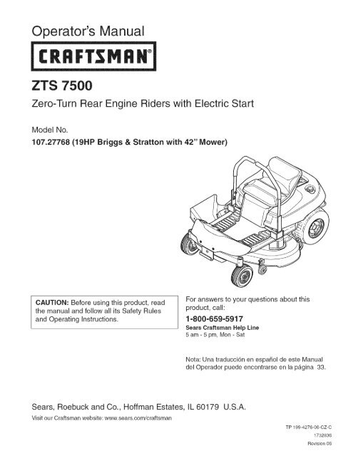
<strong>Operator's</strong> <strong>Manual</strong><br />
ZTS 7500<br />
Zero-Turn Rear Engine Riders with Electric Start<br />
Model No.<br />
107.27768 (19HP Briggs & Stratton with 42" Mower)<br />
CAUTION: Before using this product, read<br />
the manual and follow all its Safety Rules<br />
and Operating Instructions,<br />
For answers to your questions about this<br />
product, call:<br />
1-800-659-5917<br />
Sears Craftsman Help Line<br />
5 am - 5 pm, Mon- Sat<br />
Sears, Roebuck and Co., Hoffman Estates, IL 60179 U.S.A.<br />
Visit our Craftsman website: www.sears.<strong>com</strong>/craftsman<br />
Nota: Una traducci6n en espaSol de este <strong>Manual</strong><br />
del Operador puede encontrarse en la pAgina 33.<br />
TP 199-4276-06-CZ-C<br />
1732838<br />
Revision 08
Nota: Una traducci6n en espaRol de este <strong>Manual</strong> del Operador puede encontrarse en la pb,gina 35.<br />
Warranty Statement ..................................................... 2<br />
Safety Rules & information ......................................... 3<br />
identification Numbers ................................................ 7<br />
Optional Accessories .................................................. 8<br />
Literature Package Contents ...................................... 8<br />
Pre-Operation ............................................................... 9<br />
Operation .................................................................... 10<br />
Maintenance ............................................................... 17<br />
Service & Adjustments ............................................. 26<br />
Storage ....................................................................... 30<br />
Troubleshooting ......................................................... 31<br />
Spanish <strong>Operator's</strong> <strong>Manual</strong> ...................................... 33<br />
Repair Parts ......................................................... PTS=I<br />
Hardware & Torque Specifications ................... PTS=31<br />
Repair Protection Agreement ........ inside Back Cover<br />
Service Numbers ........................................ Back Cover<br />
NOTE: In this manual, "left"and "right"are referred to as seen from the operating position.<br />
LIMITED WARRANTY ON CRAFTSMAN RIDING EQUIPMENT<br />
For two (2) years from the date of purchase, if this Craftsman riding equipment is maintained, lubricated and tuned up<br />
according to the instructions in the owner's manual, Sears will repair or replace free of charge any parts that are<br />
found to be defective in material or workmanship according to the guidelines of coverage listed below. Sears will also<br />
provide free labor for these applicable warrantied parts for the two full years. During the first 30 days of purchase,<br />
there will be no charges to service the product at your home for issues covered by this warranty. (See exclusions<br />
below). For your convenience, IN HOME warranty service will still be available after the first 30 days of purchase, but<br />
a trip charge will apply. This charge will be waived if the Craftsman product is dropped off at an authorized Sears location.<br />
For the nearest authorized Sears location, please call t -800-MY-HOME. This warranty applies only while this<br />
product is within the United States.<br />
THIS WARRANTY DOES NOT COVER:<br />
• Expendable items which be<strong>com</strong>e worn during normal<br />
use, including but not limited to blades, spark plugs,<br />
air cleaners, belts, and oil filters.<br />
• Standard maintenance servicing, oil changes, or<br />
tune-ups.<br />
Tire replacement or repair caused by punctures from<br />
outside objects, such as nails, thorns, stumps, or<br />
glass.<br />
Repairs necessary because of operator abuse,<br />
including but not limited to, damage caused by towing<br />
objects beyond the capability of the riding equipment,<br />
impacting objects that bend the frame or crankshaft,<br />
or over-speeding the engine.<br />
LIMITED WARRANTY ON BATTERY<br />
Repairs necessary because of operator negligence,<br />
including but not limited to, electrical and mechanical<br />
damage caused by improper storage, failure to use<br />
the proper grade and amount of engine oil, failure to<br />
keep the deck clear of flammable debris, or failure to<br />
maintain the equipment according to the instructions<br />
contained in the owner's manual.<br />
• Engine (fuel system) cleaning or repairs caused by<br />
fuel determined to be contaminated or oxidized<br />
(stale). In general, fuel should be used within 30 days<br />
of its purchase date.<br />
Normal deterioration and wear of the exterior of the<br />
exterior finishes, or product label replacement.<br />
Riding equipment used for <strong>com</strong>mercial or rental purposes.<br />
For ninety (90) days from date of purchase, if any battery included with this riding equipment proves defective in<br />
material or workmanship and our testing determines the battery will not hold a charge, Sears will replace the battery<br />
at no charge. During the first 30 days of purchase, there will be no charges to replace the battery at your HOME. After<br />
first 30 days, for your convenience, IN-HOME warranty service will still be available but a trip charge will apply. This<br />
charge will be waived if the Craftsman product is dropped off at an authorized Sears location. FOR THE NEAREST<br />
AUTHORIZED LOCATION, PLEASE CALL 1-800-4-MY-HOME. This battery warranty applies only while this product<br />
is within the United States.<br />
This warranty gives you specific legal rights, and you may also have other rights which vary from state to state.<br />
Sears, Roebuck and Co., Dept. 817WA, Hoffman Estates, IL 60179
Readthesesafetyrulesandfollowthemclosely.Failuretoobeytheserulescouldresultin lossofcontrol<br />
of unit,severepersonal injuryordeathtoyou,or bystanders, ordamagetopropertyorequipment.<br />
This mowing deck is capable of amputating hands and feet and throwin og_bjb'ects.<br />
The triangle _, in text signifies important cautions or warnings which must be followed.<br />
GENERAL OPERATION<br />
1. Read, understand, and follow all instructions in the<br />
manual and on the unit before starting.<br />
2. Do not put hands or feet near rotating parts or under<br />
the machine. Keep clear of the discharge opening at<br />
all times.<br />
3. Only allow responsible adults, who are familiar with<br />
the instructions, to operate the unit (local regulations<br />
can restrict operator age).<br />
4. Clear the area of objects such as rocks, toys, wire,<br />
etc., which could be picked up and thrown by the<br />
blade(s).<br />
5. Be sure the area is clear of other people before mowing.<br />
Stop the unit if anyone enters the area.<br />
6. Never carry passengers.<br />
7. Do not mow in reverse unless absolutely necessary.<br />
Always look down and behind before and while travelling<br />
in reverse.<br />
8. Never direct discharge material toward anyone. Avoid<br />
discharging material against a wall or obstruction.<br />
Material may ricochet back toward the operator. Stop<br />
the blade(s) when crossing gravel surfaces.<br />
9. Do not operate the machine without the entire grass<br />
catcher, discharge guard (deflector), or other safety<br />
devices in place and operational.<br />
10. Slow down before turning.<br />
11. Never leave a running unit unattended. Always disengage<br />
the blades (PTO), set parking brake, stop<br />
engine, and remove keys before dismounting.<br />
12. Disengage blades (PTO) when not mowing. Shut off<br />
engine and wait for all parts to <strong>com</strong>e to a <strong>com</strong>plete<br />
stop before cleaning the machine, removing the grass<br />
catcher, or unclogging the discharge guard.<br />
13. Operate the machine only in daylight or good artificial<br />
light.<br />
14. Do not operate the unit while under the influence of<br />
alcohol or drugs.<br />
15 Watch for traffic when operating near or crossing<br />
roadways.<br />
16. Use extra care when loading or unloading the unit<br />
into a trailer or truck.<br />
17. Always wear eye protection when operating this unit.<br />
18. Data indicates that operators, age 60 years and<br />
above, are involved in a large percentage of power<br />
equipment-related injuries. These operators should<br />
evaluate their ability to operate the equipment safely<br />
enough to protect themselves and others from injury.<br />
TRANSPORTING AND STORAGE<br />
t. When transporting the unit on an open trailer, make<br />
sure it is facing forward, in the direction of travel. If<br />
the unit is facing backwards, wind lift could damage<br />
the unit.<br />
2. Always observe safe refueling and fuel handling practices<br />
when refueling the unit after transportation or<br />
storage.<br />
3. Never store the unit (with fuel) in an enclosed poorly<br />
ventilated structure. Fuel vapors can travel to an ignition<br />
source (such as a furnace, water heater, etc.)<br />
and cause an explosion. Fuel vapor is also toxic to<br />
humans and animals.<br />
TP 600-4103-01-ZT-UV<br />
19. Follow the manufacturer's re<strong>com</strong>mendations for wheel<br />
weights or counterweights.<br />
20. Keep in mind the operator is responsible for accidents<br />
occurring to other people or property.<br />
21. All drivers should seek and obtain professional and<br />
practical instruction.<br />
22. Always wear substantial footwear and trousers.<br />
Never operate when barefoot or wearing sandals.<br />
23. Before using, always visually check that the blades<br />
and blade hardware are present, intact, and secure.<br />
Replace worn or damaged parts.<br />
24. Disengage attachments before: refueling, removing<br />
an attachment, making adjustments (unless the<br />
adjustment can be made from the operators position).<br />
25. When the machine is parked, stored, or left unattended,<br />
lower the cutting means unless a positive<br />
mechanical lock is used.<br />
26. Before leaving the operator's position for any reason,<br />
engage the parking brake (if equipped), disengage<br />
the blades (PTO), stop the engine, and remove the<br />
key.<br />
27. To reduce fire hazard, keep the unit free of grass,<br />
leaves, & excess oil. Do not stop or park over dry<br />
leaves, grass, or <strong>com</strong>bustible materials.<br />
28. It is a violation of California Public Resource Code<br />
Section 4442 to use or operate the engine on or near<br />
any forest-covered, brush-covered, or grass-covered<br />
land unless the exhaust system is equipped with a<br />
spark arrester meeting any applicable local or state<br />
laws. Other states or federal areas may have similar<br />
laws.<br />
29. OSHA regulations may require the use of hearing<br />
protection when exposed to sound levels greater than<br />
85 dBA for an 8 hour time period.<br />
,CAUTION<br />
excess of 85 dBA at the operator's ear and<br />
This can cause machine hearing produces loss though sound levels extended in<br />
periods of exposure.<br />
Wear hearing protection when operating this<br />
machine.<br />
4. Always follow the engine manual instructions for<br />
storage preparations before storing the unit for both<br />
short and long term periods.<br />
5. Always follow the engine manual instructions for<br />
prop.er start-up procedures when returning the unit to<br />
service.<br />
6. Never store the unit or fuel container inside where<br />
there is an open flame or pilot light, such as in a<br />
water heater. Allow unit to cool before storing.
SLOPE OPERATION<br />
Slopes are a major factor related to loss-of-control and tipover<br />
accidents, which can result in severe injury or death.<br />
Operation on all slopes requires extra caution. If you cannot<br />
back up the slope or if you feel uneasy on it, do not operate<br />
on it.<br />
Control of a walk-behind or ride-on machine sliding on a<br />
slope will not be regained by the application of the brake.<br />
The main reasons for loss of control are: insufficient tire<br />
grip on the ground, speed too fast, inadequate braking, the<br />
type of machine is unsuitable for its task, lack of awareness<br />
of the ground conditions, incorrect hitching and load distribution.<br />
1. Mow across slopes, not up and down.<br />
2. Watch for holes, ruts, or bumps. Uneven terrain could<br />
overturn the unit. Tall grass can hide obstacles.<br />
3. Choose a slow speed so that you will not have to stop<br />
or change speeds while on the slope.<br />
4. Do not mow on wet grass. Tires may loose traction.<br />
5. Never mow down slopes.<br />
6. Avoid starting, stopping, or turning on a slope. If tires<br />
lose traction (i.e. machine stops forward motion on a<br />
slope), disengage the blade(s) (PTO) and drive slow<br />
off the slope.<br />
7. Keep all movement on slopes slow andgradual. Do<br />
not make sudden changes in speed or direction,<br />
which could cause the machine to rollover.<br />
8. Use extra care while operating machines with grass<br />
catchers or other attachments; they can affect the<br />
stability of the unit. Do not use on steeps slopes.<br />
9. Do not try to stabilize the machine by putting your<br />
foot on the ground (ride-on units).<br />
10. Do not mow near drop-offs, ditches, or embankments.<br />
The mower could suddenly turn over if a<br />
wheel !s over the edge of a cliff or ditch, or if an edge<br />
caves in.<br />
11. Do not use grass catchers on steep slopes.<br />
12. Do not mow slopes ifyou cannot back up them.<br />
13. See your authorized dealer/retailer for re<strong>com</strong>mendations<br />
of wheel weights or counterweights to improve<br />
stability.<br />
14. Remove obstacles such as rocks, tree limbs, etc.<br />
15. Use slow speed. Tires may lose traction on slopes<br />
even through the brakes are functioning properly.<br />
16. Do not turn on slopes unless necessary, and then,<br />
turn slowly and gradually uphill, if possible. Never<br />
mow down slopes.<br />
TOWED EQUIPMENT (RIDE-ON UNITS)<br />
t. Tow only with a machine that has a hitch designed for<br />
towing. Do not attach towed equipment except at the<br />
hitch point.<br />
2. Follow the manufacturer s re<strong>com</strong>mendations for<br />
weight limit for towed equipment and towing on<br />
slopes. See attaching a trailer under OPERATION.<br />
3. Never allow children or others in or on towed equipment.<br />
4. On slopes, the weight of the towed equipment may<br />
cause loss of traction and loss of control.<br />
5. Travel slowly and allow extra distance to stop.<br />
6. Do not shift to neutral and coast down hill.<br />
WARNING<br />
Never operate on slopes greater than 17.6 percent<br />
(10 °) which is a rise of 3-1/2 feet (106 cm) vertically in<br />
20 feet (607 cm) horizontally.<br />
Select slow ground speed before driving onto slope.<br />
Use extra caution when operating on slopes with rearmounted<br />
grass catchers.<br />
Mow across the face of slopes, not up and down,use<br />
caution when changing directions and DO NOT<br />
START OR STOP ON SLOPE.<br />
CHILDREN<br />
Tragic accidents can occur if the operator is not alert to the<br />
presence of children. Children are often attracted to the unit<br />
and the mowing activity. Never assume that children will<br />
remain where you last saw them.<br />
t. Keep children out of the mowing area and under the<br />
watchful care of another responsible adult.<br />
2. Be alert and turn unit off if children enter the area.<br />
3. Before and during reverse operation, look behind and<br />
down for small children.<br />
4. Never carry children, even with the blade(s) off. They<br />
may fall off and be seriously injured or interfere with<br />
safe unit operation. Children who have been given<br />
rides in the past may suddenly appear in the mowing<br />
area for another ride and be run over or backed over<br />
by the machine.<br />
5. Never allow children to operate the unit.<br />
6. Use extra care when approaching blind corners,<br />
shrubs, trees, or other objects that may obscure<br />
vision.<br />
EMISSIONS<br />
t. Engine exhaust from this product contains chemicals<br />
known, in certain quantities, to cause cancer, birth<br />
defects, or other reproductive harm.<br />
2. Look for the relevant Emissions Durability Period and<br />
Air Index information on the engine emissions label.<br />
IGNITION SYSTEM<br />
t. This spark ignition system coplies with Canadian<br />
ICES-002.
SERVICE AND MAINTENANCE<br />
Safe Handling of Gasoline<br />
1. Extinguish all cigarettes, cigars, pipes, and other<br />
sources of ignition.<br />
2. Use only approved gasoline containers.<br />
3. Never remove the gas cap or add fuel with the engine<br />
running. Allow the engine to cool before refueling.<br />
4. Never fuel the machine indoors.<br />
5. Never store the machine or fuel container where there<br />
is an open flame, spark, or pilot light such as near a<br />
water heater or other appliance.<br />
6. Never fill containers inside a vehicle or on a truck bed<br />
with a plastic bed liner. Always place containers on<br />
the ground away from your vehicle before filling.<br />
7. Remove gas-powered equipment from the truck or<br />
trailer and refuel it on the ground. If this is not possible,<br />
then refuel such equipment on a trailer with a<br />
portable container, rather than from a gasoline dispenser<br />
nozzle.<br />
8. Keep nozzle in contact with the rim of the fuel tank or<br />
container opening at all times until fueling is <strong>com</strong>plete.<br />
Do not use a nozzle lock-open device.<br />
9. If fuel is spilled on clothing, change clothing immediately.<br />
10. Never over-fill the fuel tank. Replace gas cap and<br />
tighten securely.<br />
11. Use extra care in handling gasoline and other fuels.<br />
They are flammable and vapors are explosive.<br />
12. If fuel is spilled, do not attempt to start the engine but<br />
move the machine away from the area of spillage and<br />
avoid creating any source of ignition until fuel vapors<br />
have dissipated.<br />
13. Replace all fuel tank caps and fuel container caps<br />
securely.<br />
Service & Maintenance<br />
1. Never run the unit in an enclosed area where carbon<br />
monoxide fumes may collect.<br />
2. Keep nuts and bolts, especially blade attachment<br />
bolts, tight and keep equipment in good condition.<br />
3. Never tamper with safety devices. Check their proper<br />
operation regularly and make necessary repairs if<br />
they are not functioning properly.<br />
4. Keep unit free of grass, leaves, or other debris buildup.<br />
Clean up oil or fuel spillage, and remove any fuelsoaked<br />
debris. Allow machine to cool before storage.<br />
5. If you strike an object, stop and inspect the machine.<br />
Repair, if necessary, before restarting.<br />
6. Never make adjustments or repairs with the engine<br />
running.<br />
7. Check grass catcher <strong>com</strong>ponents and the discharge<br />
guard frequently and replace with manufacturer s re<strong>com</strong>mended<br />
parts, when necessary.<br />
8. Mower blades are sharp. Wrap the blade or wear<br />
gloves, and use extra caution when servicing them.<br />
9. Check brake operation frequently. Adjust and service<br />
as required.<br />
10. Maintain or replace safety and instructions labels, as<br />
necessary.<br />
11. Do not remove the fuel filter when the engine is hot<br />
as spilled gasoline may ignite. Do not spread fuel line<br />
clamps further than necessary. Ensure clamps grip<br />
hoses firmly over the filter after installation.<br />
12. Do not use gasoline containingMETHANOL, gasohol<br />
containing more than 10% ETHANOL, gasoline additives,<br />
or white gas because engine/fuel system damage<br />
could result.<br />
13. If the fuel tank must be drained, it should be drained<br />
outdoors.<br />
14. Replace faulty silencers/mufflers.<br />
15. Maintain or replace safety and instruction labels as<br />
necessary.<br />
16. Use only fac!ory authorized replacement parts when<br />
making repairs.<br />
17. Always <strong>com</strong>ply with factory specifications on all settings<br />
and adjustments.<br />
18. Only authorized service locations should be utilized<br />
for major service and repair requirements.<br />
19. Never attempt to make major repairs on this unit<br />
unless you have been properly trained. Improper<br />
service procedures can result in hazardous operation,<br />
equipment damage and voiding of manufacturers<br />
warranty.<br />
20. On multiple blade mowers, take care as rotating one<br />
blade can cause other blades to rotate.<br />
21. Do not change engine governor settings or overspeed<br />
the engine. Operating the engine at excessive<br />
speed can increase the hazard of personal injury.<br />
22. Disengage drive attachments, stop the engine,<br />
remove the key, and disconnect the spark plug wire(s)<br />
before: clearing attachment blockages and chutes,<br />
performing service work, striking an object, or if the<br />
unit vibrates abnormally. After striking an object,<br />
inspect the machine for damage and make repairs<br />
before restarting and operating the equipment.<br />
23. Never place hands near the moving parts, such as a<br />
hydro pump cooling fan, when the tractor is running.<br />
(Hydro pump cooling fans are typically located on top<br />
of the transaxle).<br />
24. Units with hydraulic pumps, hoses, or motors: WARN-<br />
ING: Hydraulic fluid escaping under pressure may<br />
have sufficient force to penetrate skin and cause serious<br />
injury. If foreign fluid is injected into the skin it<br />
must be surgically removed within a few hours by a<br />
doctor familiar with this form of injury or gangrene<br />
may result. Keep body and hands away from pin<br />
holes or nozzles that eject hydraulic fluid under high<br />
pressure. Use paper or cardboard, and not hands, to<br />
search for leaks. Make sure all hydraulic fluid connections<br />
are tight and all hydraulic hoses and lines<br />
are in good condition before applying pressure to the<br />
system. If leaks occur, have the unit serviced immediately<br />
by your authorized dealer.<br />
25. WARNING: Stored energy device. Improper release<br />
of springs can result in serious personal injury.<br />
Spnngs should be removed by an authorized technician.<br />
26. Models equipped with an engine radiator: WARNING:<br />
Stored energy device. To prevent serious bodily injury<br />
from hot coolant or steam blow-out, never attempt to<br />
remove the radiator cap while the engine is running.<br />
Stop the engine and wait until it is cool. Even then,<br />
use extreme care when removing the cap.
SAFETY & OPERATION DECALS<br />
This unit has been designed and manufactured to provide<br />
you with the safety and reliability you would expect<br />
from an industry leader in outdoor power equipment<br />
manufacturing.<br />
Although reading this manual and the safety instructions<br />
it contains will provide you with the necessary basic<br />
knowledge to operate this equipment safely and effectively,<br />
we have placed several safety labels on the unit to<br />
remind you of this important information while you are<br />
operating your unit.<br />
OPERATION<br />
Decal - Operation, Upper<br />
Part No. 1727855<br />
Decal - Danger/Warning, Lower<br />
Part No. 1727856<br />
//<br />
Decal - Ignition<br />
Switch<br />
Part No. 1726526<br />
All DANGER, WARNING, CAUTION and instructional<br />
messages on your rider and mower should be carefully<br />
read and obeyed. Personal bodily injury can result when<br />
these instructions are not followed. The information is for<br />
your safety and it is important! The safety decals below<br />
are on your rider and mower.<br />
If any of these decals are lost or damaged, replace them<br />
at once. Contact a Sears Parts & Service Center for<br />
replacements.<br />
These labels are easily applied and will act as a constant<br />
visual reminder to you, and others who may use the<br />
equipment, to follow the safety instructions necessary for<br />
safe, effective operation.<br />
Decal - Cutting<br />
Height Adjustment<br />
Part No. 1726642<br />
ter or eBtire grass _t0her in ph0°<br />
Decal - Danger,<br />
Rotating Blades<br />
Part No. 1704277<br />
Decal - Transmission<br />
Release Valve<br />
Part No. 1720543<br />
Decal - Danger,<br />
Rotating Blades<br />
Part No. 1704276
_\,_ CRAFTSMAN:<br />
II<br />
_>'__w_to B71.1 - 1998 Safety Standards _<br />
When contacting the service center for replacement<br />
parts, service, or information you MUST have these<br />
numbers.<br />
Record your model name/number, manufacturer's identification<br />
numbers, and engine serial numbers in the<br />
space provided for easy access.<br />
The identification tag is located on the underside of the<br />
seat. Tilt the seat forward to access the ID tag.<br />
For answers to your questions about this product, call:<br />
1-800-659-5917<br />
Sears Craftsman Help Line, 5 am - 5 pm,<br />
Monday-Saturday.<br />
Model Description Name/Number<br />
Stock Number Unit Serial Number<br />
Date Purchased<br />
Engine Make Engine Model<br />
ID Tag<br />
Engine Type/Spec Engine Code/Serial Number
- Two Bin Bagger<br />
- Headlight Kit<br />
• Front Bumper Kit<br />
Setup instructions - Setup instructions - <strong>Operator's</strong> <strong>Manual</strong> & Parts<br />
English Spanish Book - English/Spanish<br />
Setup<br />
in6 E_y Step:<br />
Troubleshooting<br />
Keys<br />
Setup<br />
i_,_ _asv Step_:<br />
......... _,_ ,,=_,<br />
Troubleshooting<br />
Ope_to¢_ <strong>Manual</strong><br />
ZTS7_00<br />
@
m<br />
1<br />
m<br />
m<br />
m<br />
Read The <strong>Operator's</strong><br />
<strong>Manual</strong><br />
• Read the operator's manual.<br />
You should always read and follow<br />
the instructions in the operator's<br />
manual. Proper care, performance tips, and safety<br />
information is located in this important document.<br />
Always Check the Oil<br />
Level<br />
• Check the engine oil level.<br />
The engine in your tractor has been<br />
shipped, from the factory, already<br />
filled with oil for use during the engine break-in period.<br />
Always check the oil level before starting the engine.<br />
Fill=Up with FRESH<br />
Gasoline<br />
Fill the tank with fresh fuel.<br />
The single most <strong>com</strong>mon service<br />
issue is stale or contaminated fuel!<br />
Fuel should not be more than 30 days old. Use fuel<br />
stabilizer to extend the life of your fuel, and always<br />
store fuel in an approved, sealed, plastic gas can.<br />
Stale fuel clean-out<br />
ranty.<br />
is not covered under your war-<br />
%<br />
Charge The Battery<br />
• Lift the seat deck to access the<br />
battery. If the unit is put into service<br />
after the month and year indicated<br />
on the battery date tag (located on<br />
top of battery) charge the battery for<br />
one hour at 6-10 amps. Refer to the SERVICE &<br />
ADJUSTMENTS section of the operator's manual for<br />
battery charging information.<br />
Rear Tire Pressure: 10-12 PSI<br />
Front Tire Pressure: 18-20 PSi<br />
Check Tire Pressure<br />
Reduce the tire pressures to the<br />
pressures shown below. Tires are<br />
over-inflated for shipping purposes,<br />
and must be set to the correct pressures<br />
for optimum traction.<br />
m<br />
m<br />
Push Unit Off Crate<br />
To push the unit off the crate:<br />
Set BOTH transmission<br />
release levers to PUSH position<br />
by pulling the levers back<br />
(levers are located at the rear<br />
of the rider).<br />
Cut the steel banding securing rider to pallet (6<br />
bands).<br />
Move the ground speed control levers in to<br />
DRIVE positions.<br />
Set the mower cutting height to its highest setting.<br />
Fold the cardboard used to crate the unit in half,<br />
and place it under the front wheels of the unit.<br />
Push the unit forward off the crate.<br />
Set the transmission release valve levers back<br />
to DRIVE positions (levers pushed in).<br />
OFF<br />
"_, RUN<br />
_START<br />
Start The Engine<br />
To start the engine:<br />
While sitting in the operator's<br />
seat, place the ground speed<br />
control levers in PARK (levers<br />
out). Make sure the yellow<br />
PTO switch is OFF.<br />
• Move the engine throttle control fully forward to<br />
FAST.<br />
Set the choke control to CLOSED<br />
NOTE." A warm engine may not require choking. In<br />
this case, set the choke control to OPEN.<br />
Insert the key into the ignition switch and turn it<br />
to START.<br />
After the engine starts, gradually move the<br />
choke control to OPEN position. Warm the<br />
engine by running it for at least a minute before<br />
turning on the PTO switch, or driving the unit.<br />
After warming the engine, ALWAYS operate<br />
the unit with the throttle set to FAST position<br />
when mowing.<br />
• See the OPERATION section for driving information.
,4F<br />
Left Right<br />
GroundSpeed& GroundSpeed&<br />
ParkingBrake Parking8rake<br />
Lever Lever<br />
Fuel Tank<br />
Cap<br />
I__ _ _1_1<br />
GroundSpeedLevers- GroundSpeedLevers-<br />
DRIVEPesitens PARKPesitens<br />
CONTROL FUNCTIONS<br />
Transmission<br />
ReleaseLevers<br />
_ Throttle<br />
(Fast)<br />
Throttle<br />
(Slow)<br />
Choke<br />
(Closed)<br />
I Choke<br />
(Open)<br />
Figure 1. Controls<br />
The information below briefly describes the function of individual controls. Starting, stopping, driving, and mowing<br />
require the <strong>com</strong>bined use of several controls applied in specific sequences. To learn what <strong>com</strong>bination and sequence<br />
of controls to use for various tasks please read the entire section.<br />
Ground Speed Levers/<br />
Parking Brake<br />
These levers control the ground speed and parking brake<br />
of the rider. The left lever controls the left rear drive<br />
wheel and the right lever controls the right rear drive<br />
wheel and parking brake.<br />
Pushing the levers out, away from the operator's lap<br />
locks the parking brake in PARK position (inset, Figure<br />
1). Pulling the levers in across the operator's lap puts the<br />
levers in DRIVE positions.<br />
From DRIVE position, moving a lever forward increases<br />
the FORWARD speed of the associated wheel. Pulling<br />
back on a lever increases the REVERSE speed. The further<br />
a lever is pushed, the faster the drive wheel will turn.<br />
See DRIVING PRACTICE for steering instructions.<br />
10<br />
_ Throttle Control<br />
The throttle controls engine speed. Always operate at<br />
FULL throttle when mowing. Move the lever forward to<br />
the detent for FULL throttle (FAST). Move the throttle<br />
back to decrease engine speed to iDLE (SLOW).<br />
Choke<br />
Close the choke for cold starting. Open the choke once<br />
the engine starts. A warm engine may not require choking.<br />
Move the lever forward to close the choke. Move the<br />
lever back to open the choke.
Mower Height of Cut Adjustment<br />
To adjust cutting height, rotate the turn crank clockwise<br />
to raise the mower deck and counterclockwise to lower<br />
the mower deck.<br />
ignition Switch<br />
The ignition switch starts and stops the engine; it has<br />
three positions:<br />
OFF Stops the engine and shuts off the<br />
electrical system.<br />
RUN Allows the engine to run and powers the<br />
electrical system.<br />
START Cranks the engine for starting.<br />
NOTE." Never leave the ignition switch in the RUN position<br />
with the engine stopped. This drains the battery.<br />
B Hour Meter<br />
The hour meter measures the number of hours the key<br />
has been in the RUN position.<br />
NOTE." The hour meter will register the passage of time<br />
when the key is in the RUN position, even if the engine is<br />
not running.<br />
GENERAL OPERATING SAFETY<br />
Before first time operation:<br />
• Be sure to read all information in the Safety and<br />
Operation sections before attempting to operate this<br />
rider and mower.<br />
• Be<strong>com</strong>e familiar with all of the controls and how to stop<br />
the unit.<br />
• Drive in an open area without mowing to be<strong>com</strong>e accus-<br />
tomed to driving the unit.<br />
11<br />
PTO Switch<br />
The PTO (Power Take-Off) switch engages and disengages<br />
the mower deck. To turn the mower on, pull the<br />
switch UP. Push the switch DOWN to turn the mower off.<br />
Note that the operator must be seated firmly in the rider<br />
seat for the PTO to function.<br />
Transmission Release Levers<br />
The transmission release levers deactivate the transmissions<br />
so that the unit can be pushed by hand. See<br />
PUSHING THE UNIT BY HAND for operational information.<br />
Fuel Tank<br />
To remove the cap, turn counterclockwise.<br />
,WARNING<br />
if you do not understand how a specific control<br />
functions, or have not yet thoroughly read the<br />
CONTROL FUNCTIONS section, do so now.<br />
Do NOT attempt to operate the rider without first<br />
be<strong>com</strong>ing familiar with the location and function<br />
of ALL controls.
CHECKS BEFORE STARTING<br />
• Check that the crankcase oil is filled to full mark on<br />
dipstick.<br />
• Fill the fuel tank with fresh fuel.<br />
FUEL RECOMMENDATIONS<br />
For daily operation: Use only unleaded gasoline with a<br />
pump sticker octane rating of 87 or higher. Gasohol (up<br />
to 10% ethyl alcohol, 90% unleaded gasoline by volume)<br />
is approved as a fuel. Methyl Teriary Butyl Ether (MTBE)<br />
and unleaded gasoline blends (up to a maximum of 15%<br />
MTBE by volume) are approved as a fuel. No other gasoline/alcohol<br />
or gasoline/ether blends are approved. Do<br />
not use fuel additives other than fuel stabilizer.<br />
For storage: CAUTION: Alcohol blended fuels (called<br />
gasohol or using ethanol or methanol) can attract moisture<br />
which leads to separation and formation of acids<br />
during storage. Acidic gas can damage the fuel system<br />
of an engine while in storage.<br />
To avoid engine problems always use fuel stabilizer,<br />
especially before storage of 30 days or longer. Use fresh<br />
fuel next season. See STORAGE instructions for additional<br />
information.<br />
Never use engine or carburetor cleaner products in the<br />
fuel tank or permanent damage may occur. To add fuel:<br />
1. Remove the fuel cap (B, Figure 2).<br />
2. Fill the tank. Do not overfill. Leave room in the tank<br />
for fuel expansion.<br />
3. Install and hand tighten the fuel cap.<br />
WARNING<br />
Never allow passengers to ride on the unit.<br />
Before leaving the operator's position for any<br />
reason, engage the parking brake, disengage the<br />
PTO, stop the engine and remove the key.<br />
To reduce fire hazard, keep the engine, rider and<br />
mower free of grass, leaves and excess grease.<br />
Do not stop or park rider over dry leaves, grass or<br />
<strong>com</strong>bustible materials.<br />
Gasoline is highly flammable and must be<br />
handled with care. Never fill the tank when the<br />
engine is still hot from recent operation. Do not<br />
allow open flame, smoking or matches in the area.<br />
Avoid over=filling and wipe up any spills.<br />
12<br />
Figure 2. Pre-Start Checks<br />
A. Fuel Tank Cap<br />
WARNING<br />
Never operate on slopes greater than 17.6 percent<br />
(10 °) which is a rise of 3-1/2 feet (106 cm)<br />
vertically in 20 feet (607 cm) horizontally.<br />
Select slow ground speed before driving onto a<br />
slope. Use extra caution when operating on<br />
slopes with a rear-mounted grass catcher.<br />
Mow across the face of slopes, not up and down.<br />
Use caution when changing directions and DO<br />
NOT START OR STOP ON A SLOPE.<br />
WARNING - TRAILERS<br />
Do not load this zero-turn rider on a trailer or<br />
truck using two separate ramps. Only use a<br />
single ramp that is at least one foot wider than<br />
the width of the rear wheels of this rider. This<br />
rider has a zero turning radius and the wheels<br />
could fall off the ramps, or the rider could tip over<br />
injuring the operator or bystanders.
EMERGENCY STOPPING<br />
In the event of an emergency the engine can be stopped<br />
by simply turning the ignition switch to STOR Use this<br />
method only in emergency situations. For normal engine<br />
shut down follow the procedure given in STOPPING THE<br />
RIDER AND ENGINE.<br />
STOPPING THE RIDER & ENGINE<br />
1. Returning the ground speed control levers to PARK<br />
positions will stop rider movement and engage the<br />
parking brake.<br />
2. Stop the mower by pushing down on the PTO switch.<br />
3. Move the throttle control to SLOW position and turn<br />
the ignition key to OFR Remove the key.<br />
STARTING THE ENGINE<br />
1. While sitting in the operator's seat, make sure the<br />
PTO switch is OFF and the ground speed control<br />
levers are locked in PARK positions.<br />
2. Move the engine throttle control fully forward to FAST.<br />
Set the choke control to CLOSED.<br />
NOTE: A warm engine may not require choking. In this<br />
case, set the choke control to OPEN.<br />
3. Insert the key into the ignition switch and turn it to<br />
START.<br />
4. After the engine starts, gradually move the choke<br />
control back to OPEN position. Warm the engine by<br />
running it for at least a minute before turning on the<br />
PTO switch, or driving the unit.<br />
5. After warming the engine, ALWAYS operate the<br />
unit with the throttle set to FAST, especially when<br />
mowing.<br />
MOWING<br />
1. Make sure the PTO switch is OFF, the ground speed<br />
control levers are locked in their PARK positions, and<br />
the operator is in the seat.<br />
2. Set the mower cutting height to the desired setting.<br />
3. Start the engine (see STARTING THE ENGINE).<br />
4. Set the throttle to FAST.<br />
5. Turn the PTO switch ON to engage the mower deck.<br />
6. Move the ground speed control levers from PARK<br />
positions to drive positions (levers in across the operator's<br />
lap).<br />
7. Begin mowing. See DRIVING PRACTICE.<br />
8. When finished, turn the PTO switch OFR<br />
9. Stop the engine (see STOPPING THE RIDER AND<br />
ENGINE).<br />
PUSHING THE RIDER BY HAND<br />
1. Turn the PTO switch OFF, set the ground speed control<br />
levers to PARK, turn the ignition switch OFF,<br />
remove the key, and wait for all moving parts to stop.<br />
2. Locate the transmission release levers (C, Figure 3)<br />
at the rear of the unit.<br />
3. Pull both levers back and down to release the trans-<br />
missions (position B, Figure 3).<br />
4. Set the ground speed control levers to DRIVE positions<br />
(levers moved in).<br />
The rider can now be pushed by hand.<br />
5. After moving the rider, set the ground speed control<br />
levers to PARK and push both transmission release<br />
levers forward to re-engage the transmissions (position<br />
A, Figure 3).<br />
® DO<br />
NOTTOW RIDER<br />
Towing the unit will cause transmission damage.<br />
Do not use another vehicle to push or<br />
pull this unit.<br />
Figure 3. Transmission Release Levers<br />
A. Drive Position<br />
B. Push Position<br />
C. Transmission Release Levers<br />
13
DRiViNG PRACTICE-<br />
BASIC DRIVING<br />
WARNING: Never operate on slopes greater than 17.6%<br />
(10°). See SLOPE OPERATION in the safety section.<br />
Zero turn riders operate differently from other burwheeled<br />
vehicles. The drive wheels are also your steering<br />
wheels. If you cannot drive the unit on a hill, you will<br />
not be able to steer the unit on it. Operating zero turn<br />
units on slopes requires extra caution.<br />
The lever controls of the zero turn rider are very responsive,<br />
and learning to gain a smooth and efficient control<br />
of the rider's forward, reverse, and turning movements<br />
will take some practice.<br />
Spend some time going through the following maneuvers<br />
and be<strong>com</strong>ing familiar with how the unit accelerates,<br />
travels, and steers -- before you begin mowing --is<br />
absolutely essential to getting the most out of the zero<br />
turn rider.<br />
Locate a smooth, fiat area of your lawn -- one with<br />
plenty of room to maneuver. (Clear the area of objects,<br />
people and animals before you begin.) Operate the unit<br />
at mid-throttle during this practice session (ALWAYS<br />
operate at full throttle when mowing), and turn slowly to<br />
prevent tire slippage and damage to your lawn.<br />
We suggest you begin with the Smooth Travel procedure<br />
to the right, and then advance through the forward,<br />
reverse, and turning maneuvers.<br />
WARNING<br />
Do not mow in reverse unless absolutely<br />
necessary. Always look down and behind before<br />
and while travelling in reverse.<br />
Forward Travel<br />
Smooth Travel<br />
The lever controls of the<br />
zero turn rider are<br />
highly responsive.<br />
The BEST method of<br />
handling the ground<br />
speed control levers is in<br />
three steps -- as shown<br />
in Figure 4.<br />
FIRST place your hands<br />
onto the levers as<br />
shown.<br />
SECOND, to go forward<br />
gradually push the levers<br />
forward with your palms.<br />
THIRD, to speed up<br />
move the levers farther<br />
forward. To slow down<br />
smoothly, slowly move<br />
the levers back toward<br />
neutral.<br />
Forward Travel Practice<br />
Figure 4. Move Control<br />
Levers Gradually<br />
Gradually move both ground speed control levers evenly<br />
FORWARD from neutral. Slow down and repeat.<br />
Reverse Travel Practice<br />
LOOK DOWN & BEHIND, then gradually move both<br />
ground speed control levers evenly BACK from neutral.<br />
Slow down and repeat.<br />
NOTE: Practice backing up for several minutes before<br />
attempting to do so near objects. The rider turns as<br />
sharply in reverse as when going forward, and backing<br />
up straight takes practice.<br />
Reverse Travel<br />
Figure 5. Forward Travel Figure 6. Reverse Travel<br />
14
Practice Turning Around a Corner<br />
While traveling forward allow one handle to gradually<br />
return back toward neutral. Practice several times before<br />
mowing.<br />
NOTE." To prevent damaging your lawn by pivoting directly<br />
on the tire tread, it is best to keep both wheels going at<br />
least slightly forward.<br />
Practice Turning in Place<br />
Executing Turns Turning In Place<br />
To "zero turn" means to turn in place. To turn in place,<br />
gradually move one ground speed control lever forward<br />
from neutral and one lever back from neutral simultaneously.<br />
Repeat several times.<br />
Figure 7. RightTurn Figure 8. Turning in Place<br />
ADVANCED DRIVING<br />
Executing an End=Of=Row Zero<br />
Turn<br />
Your zero turn rider's unique ability to turn in<br />
place allows you to turn around at the end of<br />
a cutting row rather than having to stop and<br />
make a Y-turn before starting a new row.<br />
For example, to execute a right end-of row<br />
zero turn:<br />
1. Slow down at the end of the row.<br />
2. Move the LEFT ground speed control<br />
lever forward slightly while moving the<br />
RIGHT ground speed control lever back to<br />
center and then slightly back from center.<br />
3. Begin mowing forward again.<br />
This technique turns the rider RIGHT and<br />
slightly overlaps the row just cut --eliminating<br />
the need to back up and re-cut missed grass.<br />
As you be<strong>com</strong>e more familiar and experienced<br />
with operating the zero turn rider, you<br />
will learn more maneuvers that will make your<br />
mowing time easier and more enjoyable.<br />
Remember, the more you practice, the bet=<br />
ter your control of the rider will be!<br />
15<br />
Figure 9. Executing an End-Of-RowTurn
MOWER DECK REMOVAL &<br />
INSTALLATION<br />
NOTE: Perform mower removal and installation on a<br />
hard, level surface such as a concrete floor.<br />
WARNING<br />
Engage parking brake, disengage PTO, stop<br />
engine and remove key before attempting to<br />
install or remove the mower.<br />
Removing the Mower Deck<br />
1. Turn the PTO off, put the control levers in PARK position,<br />
turn the ignition OFF, remove the key, and wait<br />
for all moving parts to stop.<br />
2. Pivot the rider's front wheels forward.<br />
3. Place the cutting height adjustment crank (D, Figure<br />
10) in the lowest cutting position.<br />
4. Release tension on the drive belt using the mower<br />
belt release lever (E, Figure 10) and remove the drive<br />
belt from the engine pulley.<br />
5. Disconnect the front hitch by removing the hitch rod<br />
and clip (A, Figures 10 & 11), and lifting the mower<br />
hitch (B) up and off the rider hitch bracket (D).<br />
6. Slide the mower deck forward until the rear mower<br />
supports (C) disengage the frame of the rider.<br />
7. Slide the mower deck out from under the right side of<br />
the rider.<br />
Installing the Mower Deck<br />
1. Pivot the rider's front wheels forward.<br />
2. Place the cutting height adjustment crank (D, Figure 10)<br />
in the lowest cutting position.<br />
3. Slide the mower deck under the right side of the rider.<br />
Slide the mower backwards making sure that the rear<br />
mower supports (C, Figure 11) slide up the ramps on<br />
the frame. The rear of the mower is supported by<br />
these frame ramps.<br />
4. Hang the mower hitch (B, Figure 11) on the rider<br />
hitch bracket (D) and secure with the hitch rod and<br />
clip (A).<br />
5. Use the mower belt release lever (D, Figure 12) to<br />
release tension on the mower idler pulley, and install<br />
the drive belt as shown in Figure 12.<br />
16<br />
®<br />
Figure 10. Mower Components<br />
A. Hitch Rod and Clip<br />
B. Mower Hitch<br />
C. Rear Mower Supports<br />
D. Cutting Height Adjustment Crank<br />
E. Mower Belt Release Lever<br />
Figure 11. Mower Hitch Components<br />
A. Hitch Rod and Clip<br />
B. Mower Hitch<br />
C. Rear Mower Supports<br />
D. Rider Hitch Bracket<br />
Figure 12. Mower Belt Routing<br />
A. Engine Pulley<br />
B. Mower Drive Belt<br />
C. Back=Side Idler Pulleys<br />
D. Mower Belt Release Lever<br />
E. Arbor Pulleys
MAINTENANCE SCHEDULE<br />
The following schedules should be followed for normal care of your rider and mower.<br />
RIDER MAINTENANCE, All Models Before Spring 8 25 100 200 IYearly<br />
Each Use & Fall Hours Hours Hours Hours<br />
Clean Debris from Rider and Engine Compartment * ®<br />
Clean Debris from Engine Cooling Areas & Air Filter * ®<br />
Check Tire Pressure •<br />
Lubricate Rider & Mower * •<br />
Clean Deck & Check/Replace Mower Blades •<br />
Clean Battery & Cables •<br />
Check Rider Safety System ** ® ® ®<br />
Check / Adjust PTO Clutch •<br />
ENGINE MAINTENANCE, 8 Hours 25 Hours 50 Hours 100 Hours 200 Hours or Yearly<br />
19HP Briggs & Stratton or Daily or Every or Every or Every Every Season<br />
Season Season Season<br />
Check Engine Oil Level * ®<br />
Service Air Pre-Cleaner * ®<br />
Change Oil * •<br />
Service Air Filter * •<br />
Change Oil & Filter * •<br />
Clean Cooling Fins * •<br />
Replace Air Filter * •<br />
Replace Spark Plugs •<br />
Replace Fuel Filter 1 •<br />
Check Valve Clearance 1 •<br />
* More often in hot (over 85 ° F: 30 ° C) weather or dusty operating conditions.<br />
** Check the function of the safety system after the unit has been stored for 30 days or longer.<br />
1 These services should be performed by Sears or other qualified service dealer.<br />
17
Rider Maintenance items<br />
CLEAN DEBRIS FROM RIDER AND<br />
ENGINE COMPARTMENT<br />
Service IntervaJ: Before each use.<br />
CAUTION: if debris is not removed from the engine<br />
<strong>com</strong>partment and other hot surfaces, it creates a fire<br />
hazard. Before starting the unit at the beginning of the<br />
mowing session, remove any grass clippings, dirt,<br />
leaves, or other debris from the unit. Also clean out the<br />
engine <strong>com</strong>partment.<br />
CLEAN DEBRIS FROM ENGINE<br />
COOLING AREAS AND AIR FILTER<br />
Service interval: Before each use.<br />
CAUTION: if debris is not removed from the engine<br />
<strong>com</strong>partment and other hot surfaces, it creates a fire<br />
hazard. Before starting the unit at the beginning of the<br />
mowing session, lift the seat deck and clean any debris<br />
from the intake screen on top of the engine (A, Figure<br />
13), exposed engine cooling fins, and around the air filter<br />
assembly. Also open the air filter cover (B) and remove<br />
any debris that has accumulated in the air filter <strong>com</strong>partment.<br />
CHECKTIRE PRESSURE<br />
Service Interval: 25 Hours.<br />
Tire pressure should be checked periodically, and maintained<br />
at the levels shown in Figure 14. Note that these<br />
pressures may differ slightly from the "Max Inflation"<br />
stamped on the side-wall of the tires. The pressures<br />
shown provide proper traction, improve cut quality, and<br />
extend tire life.<br />
18<br />
Figure 13. Engine Compartment<br />
A. intake Screen<br />
B. Air Filter Cover<br />
Tire Pressure<br />
Front 18-20 psi (1,24-1,38 bar)<br />
Rear 10-12 psi (,69-,83 bar)<br />
Figure 14. Tire Pressures
LUBRiCATiON<br />
Service Interval: 25 hours.<br />
Lubricate the unit at the locations shown in Figures 15<br />
through 17 as well as the following lubrication points.<br />
Grease:<br />
• front wheel bushings<br />
• mower pivots<br />
f ,,front<br />
• mower<br />
wheel<br />
arbors<br />
grease fittings<br />
Use grease fittings when present.<br />
Not all greases are <strong>com</strong>patible. Use automotive-type lithium<br />
grease.<br />
Oil:<br />
• hydro linkage<br />
• rear frame assembly pivot<br />
• brake linkage<br />
frame pivot points<br />
• mower deck height adjustment linkage<br />
• brake linkage<br />
Figure 15a. Mower Lubrication<br />
Figure 15b. Arbor Lubrication (3-Blade Model Shown)<br />
19<br />
Generally, all moving metal parts should be oiled where<br />
contact is made with other parts. Keep oil and grease off<br />
belts and pulleys. Remember to wipe fittings and surfaces<br />
clean both before and after lubrication.<br />
Figure 16. Lubricating Rider<br />
\<br />
\<br />
Figure 17. Lubricating Rider
CLEAN DECK &<br />
CHECK / REPLACE MOWER BLADES<br />
Service Intervah 25 hours or as required.<br />
WARNING<br />
For your personal safety, do not handle the sharp<br />
mower blades with bare hands. Careless or<br />
improper handling of blades may result in serious<br />
injury.<br />
WARNING<br />
For your personal safety, blade mounting<br />
capscrews must each be installed with two spring<br />
washers or a hex washer and spring washer, then<br />
securely tightened. Torque blade mounting nut to<br />
80 - 90 ft. Ibs. (108 - 122 Nm).<br />
1. Remove mower deck (see "Mower Deck Removal" in<br />
the OPERATION section).<br />
2. See Figure 18. Remove blade to inspect it or to safely<br />
access the underside of the mower deck. Use a<br />
block of wood to prevent blade rotation while loosening<br />
the capscrew by turning it counterclockwise.<br />
3. Remove the capscrew (D, Figure 20), spring washer<br />
(C), hex washer (B), and blade.<br />
4. Clean the underside of the mower deck.<br />
5. Inspect the blades for nicks or dull edges. Use a file<br />
to sharpen blade to a fine edge. If the blade is damaged,<br />
it must be replaced.<br />
6. Balance the blade as shown in Figure 19. Center the<br />
blade's hole on a nail lubricated with a drop of oil. A<br />
balanced blade will remain level. If the blade is not<br />
balanced, continue to sharpen the heavy side until it<br />
balances.<br />
7. Reinstall the blade with the lift wings (D, Figure 20)<br />
pointing up toward the mower deck as shown.<br />
8. Reinstall the spring washers (B, Figure 20) and nut<br />
(C). Use a wooden block (A) to prevent blade rotation<br />
while tightening the nut (C) to 80-90 ft. Ibs. (108-122<br />
Nm).<br />
2O<br />
Figure 18. Blade Removal<br />
Workbench<br />
C<br />
Figure 19. Balancing The Blade<br />
Figure 20. Blade installation<br />
A. 4x4 Wood Block C. Blade Nut<br />
B. Spring Wshers D. Lift Wings<br />
Nail
CLEANING THE BATTERY AND<br />
CABLES<br />
WARNING<br />
Be careful when handling the battery. Avoid<br />
spilling electrolyte. Keep flames and sparks away<br />
from the battery.<br />
When removing or installing battery cables,<br />
disconnect the negative cable FIRST and reconnect<br />
it LAST. if not done in this order, the positive<br />
terminal can be shorted to the frame by a tool.<br />
Always wear safety glasses and gloves when<br />
handling batteries.<br />
Service interval: 100 Hours<br />
1. Disconnect the cables from the battery, negative<br />
cable first (B, Figure 21).<br />
2. Remove the rubber strap securing the battery, and<br />
remove the battery.<br />
3. Clean the battery and battery <strong>com</strong>partment with a<br />
solution of baking soda and water.<br />
4. Clean the battery terminals and cable ends with a<br />
wire brush until shiny.<br />
5. Reinstall the battery and secure with the rubber strap.<br />
6. Reattach the battery cables: first attach the positive<br />
cable (see A, Figure 21), then attach the negative<br />
cable (B).<br />
7. Coat the cable ends and battery terminals with petroleum<br />
jelly or non-conducting grease.<br />
Figure 21. Engine Compartment<br />
A. Positive (+) Battery Cable<br />
B. Negative (-) Battery Cable<br />
21<br />
CHECK RIDER SAFETY<br />
SYSTEM<br />
Service Interval: Every 100 hours, every spring/fall,<br />
and after storage of 30 days or longer.<br />
This unit is equipped with safety interlock switches.<br />
These safety systems are present for your safety. Do<br />
not attempt to bypass safety switches, and never tamper<br />
with safety devices. Check their operation regularly.<br />
Operational SAFETY Checks<br />
TEST 1 -- ENGINE SHOULD NOT CRANK IF:<br />
* PTO switch is ON, OR<br />
* Ground speed control levers are not in their PARK<br />
positions.<br />
TEST 2 -- ENGINE SHOULD CRANK IF:<br />
* PTO switch is OFF, AND<br />
* Ground speed control levers are in their PARK positions.<br />
TEST 3 -- ENGINE SHOULD SHUT OFF IF:<br />
* Operator rises off seat with the PTO ON, OR<br />
* Operator rises off seat with the ground speed levers<br />
in DRIVE positions, OR<br />
* Operator moves the left ground speed control lever<br />
out of its PARK position while leaving the right lever<br />
in park (both levers must be moved from PARK to<br />
DRIVE position simultaneously to avoid shutoff).<br />
TEST 4 -- BLADE BRAKE CHECK<br />
The mower blades and mower drive belt should <strong>com</strong>e<br />
to a <strong>com</strong>plete stop within five seconds after the PTO<br />
switch is turned OFR if mower drive belt does not stop<br />
within five seconds, contact a Sears Parts & Repair<br />
Center.<br />
NOTE: Once the engine has stopped, the PTO switch<br />
must be turned OFF and the ground speed control<br />
levers must be locked in their PARK positions in order<br />
to start the engine.<br />
WARNING<br />
if the unit does not pass a safety test, do not<br />
operate it. See a Sears Parts & Repair Center.<br />
Under no circumstance should you attempt to<br />
defeat the purpose of the safety interJock<br />
system.
CHECK / ADJUST PTO CLUTCH<br />
• ILWARNING<br />
To avoid serious injury, perform adjustments only<br />
with engine stopped, key removed and tractor on<br />
level ground.<br />
Service interval: 200 Hours.<br />
The PTO clutch is engaged and disengaged by the PTO<br />
switch. The clutch powers and brakes the mower blades.<br />
Check the PTO clutch adjustment every 200 hours of<br />
operation. Also perform the following procedure if the<br />
clutch is slipping, will not engage, or if a new clutch has<br />
been installed.<br />
1. Remove key from ignition switch and disconnect<br />
spark plug wires to prevent the possibility of accidental<br />
starting while the PTO is being adjusted.<br />
2. See Figure 22. Note the position of the 3 adjustment<br />
windows (A) in the side of the brake plate and the<br />
nylock adjustment nuts (B).<br />
3. Insert a .012"-.015" (2,5-4mm) feeler gauge (C)<br />
through each window, positioning the gauge between<br />
the rotor face and the armature face as shown in<br />
Figure 23.<br />
4. Alternately tighten the adjustment nuts (B, Figure 22)<br />
until the rotor face and armature face just contacts<br />
the gauge.<br />
5. Check the windows for an equal amount of tension<br />
when the gauge is inserted and removed, and make<br />
any necessary adjustments by tightening or loosening<br />
the adjustment nuts.<br />
NOTE: The actual air gap between the rotor and armature<br />
may vary even after performing the adjustment procedure.<br />
This is due to dimensional variations on <strong>com</strong>ponent<br />
parts, and is an acceptable condition.<br />
6. Check the mower blade stopping time. The mower<br />
blades and mower drive belt should <strong>com</strong>e to a <strong>com</strong>plete<br />
stop within five seconds after the electric PTO<br />
switch is turned off. If adjustment does not stop a<br />
mower braking problem, replace the electric PTO<br />
clutch.<br />
22<br />
Figure 22. PTO Clutch Adjustment<br />
A. Adjustment Window (Qty. 3, one shown)<br />
B. Adjustment Nut<br />
Figure 23. Adjust PTO Clutch<br />
A. Window<br />
B. Adjustment Nut<br />
C. Feeler Gauge
CHECK ENGINE OIL LEVEL<br />
Service Interval: Before each use, and every 8 hours.<br />
1. Turn the engine off, and set the parking brake to<br />
PARK.<br />
2. Clean the area around the dip stick (C, Figure 25).<br />
3. Remove the dip stick (C) and clean it with a paper<br />
towel.<br />
4.<br />
5.<br />
Insert the dip stick back into the engine. Thread the<br />
cap back onto the tube (D).<br />
Remove the dip stick and read the oil level. The oil<br />
level should be between the "FULl" and "ADD" marks<br />
(D). If not, add oil according to the oil re<strong>com</strong>mendations<br />
chart (Figure 24).<br />
CHANGE ENGINE OIL<br />
Service Interval: 50 hours or once per season.<br />
Oil Capacity: 1-7/8 quarts (1.8L) without filter change.<br />
NOTE." Change engine oil while the engine b warm. Run<br />
the engine for a few minutes, then shut the engine off<br />
and allow it to cool from hot to warm.<br />
1. Clean the area around the dip stick (C, Figure 25)<br />
and oil drain tube (A).<br />
2. Remove the oil drain plug (A) from the end of the oil<br />
drain tube. Remove the dip stick (C). Allow ample<br />
time for <strong>com</strong>plete drainage.<br />
3. Reinstall the oil drain plug (A) and route the hose<br />
next to the engine.<br />
4. Fill the crankcase with oil. See CHECK ENGINE OIL<br />
LEVEL above.<br />
CHANGE ENGINE OIL & FILTER<br />
Service Interval: 100 hours or once per season.<br />
Oil Capacity: 2 quarts (1.9L) with oil filter change.<br />
NOTE: Change engine oil while the engine is warm. Run<br />
the engine for a few minutes, then shut the engine off<br />
and allow it to cool from hot to warm.<br />
1. Clean the area around the dip stick (C, Figure 25)<br />
and oil drain (A).<br />
2. Remove the oil drain plug (A) and dip stick (C). Allow<br />
ample time for <strong>com</strong>plete drainage.<br />
3. Remove the oil filter (B). Discard the filter.<br />
4. Using a drop of oil on your finger tip, wet the rubber<br />
gasket on the bottom of the new filter.<br />
6. Turn the filter clockwise until the rubber gasket meets<br />
the filter base. Then turn 1/2 to 3/4 turn more.<br />
7. Reinstall the oil drain plug (A).<br />
23<br />
Useoil classifiedAPI Service Class SF,<br />
SG, SH, SJ or betterwith SAEViscosity:<br />
I I i --<br />
°F -20 0 20 32 40 60 80 100<br />
°C -30 -18 -7 O 4 16 27 38<br />
*CAUTION: Air cooled engines run hotter than automotive engines.<br />
Tile use of n0n-synthetic multi-visc0sity oils (5W-30, 10W-30, etc.)<br />
in temperatures above 400 F(4°0) will result in higher than normal<br />
oil consumption. When using a multi-viscosity oil, check oil level<br />
more frequently.<br />
**CAUTION: SAE 30 oil, if used below 400F (4°0), will result in hard<br />
starting and possible engine bore damage due to inadequate<br />
lubrication.<br />
Figure 24. Re<strong>com</strong>mended Engine Oil -<br />
Briggs & Stratton Models<br />
Figure 25. Oil Change =Briggs & Stratton Models<br />
A. Oil Drain Tube<br />
B. Oil Filter<br />
C. Dip Stick<br />
D. Checking Oil Level<br />
8. Fill the crankcase with oil. See CHECK ENGINE OIL<br />
LEVEL above.<br />
9. Test run the engine to check for leaks. Stop the<br />
engine for 1 minute, then recheck the oil level.<br />
v
AiR FILTER & PRE-CLEANER<br />
Service interval: Pre-Cleaner: Every 25 hours or as<br />
required. Air Filter: Every 50 hours or as required.<br />
Replacement interval: Pre-Cleaner: As required. Air<br />
Filter: Every 200 hours or once per season.<br />
Air Filter Removal & Installation<br />
1. Lift up on the bottom of the latch (A, Figure 26 or 27)<br />
and flip the latch away from the cover.<br />
2. Remove the cover (B). Remove the filter (C, Figure<br />
27) and pre-cleaner (D).<br />
3. Install the pre-cleaner (D) with the mesh side up.<br />
Install the filter (C) as shown.<br />
4. Install the cover (B, Figure 27) making sure the tabs<br />
are inserted into their slots. Secure with the latch (A).<br />
24<br />
•<br />
Figure 26. Air Filter Assembly - Briggs & Stratton<br />
Single Cylinder Models<br />
A. Air Filter Latch<br />
B. Air Filter Cover<br />
Figure 27. Air Filter Service = Briggs & Stratton<br />
Single Cylinder Models<br />
A. Air Filter Latch<br />
B. Air Filter Cover<br />
C. Air Filter<br />
D. Pre=Cleaner<br />
•<br />
®
Pre=Cleaner Service<br />
NOTE: Replace a worn or damaged pre-cleaner.<br />
1. Figure 28. Wash the pre-cleaner in liquid detergent<br />
and water.<br />
2. Squeeze the pre-cleaner dry and saturate with<br />
engine oil. Remove all excess oil by squeezing the<br />
pre-cleaner in an absorbent cloth.<br />
Air Filter Service<br />
NOTE: Replace a worn or damaged air filter.<br />
1. Figure 28. If stamped "Washable," the filter can be<br />
washed with warm water and mild soap.<br />
2. Rinse with tap water with the screen side UP allowing<br />
dirt and debris to filter out.<br />
3. Allow the filter to dry overnight before reinstalling.<br />
REPLACE SPARK PLUG<br />
Service Interval: Yearly<br />
Replacement Spark Plug: 71/500/691043<br />
Spark Plug Gap: .030" (.76mm)<br />
1. Stop the engine and allow it to cool.<br />
2. Clean the area around the spark plug.<br />
3. Remove the spark plug.<br />
4. Check the spark plug gap. It should be .030" (see<br />
Figure 29).<br />
5. Reinstall the plug into the cylinder head. Torque the<br />
plug to 180 in. Ibs (20 N.m.).<br />
25<br />
Pre-Cleaner<br />
=<br />
Figure 28. Air Filter Service<br />
_ "030i"<br />
Figure 29. Spark Plug Gapping<br />
=
GROUND SPEED CONTROL LEVER<br />
ADJUSTMENT<br />
The control levers have three adjustments:<br />
To Adjust Control Lever Height: Pull the levers in<br />
across the operator's lap to their DRIVE positions.<br />
Loosen the mount bolts (D, Figure 30) and raise or lower<br />
the levers to the desired position. Tighten the mounting<br />
bolts.(D).<br />
To Adjust Control Lever End Gap: The control lever<br />
end gap should be adjusted so that the levers do not<br />
contact each other when placed in DRIVE positions.<br />
Loosen the jam nut (A, Figure 30) and adjust the length<br />
of the carriage bolt (B) so that the levers do not contact<br />
each other. Repeat on the opposite side. Tighten the<br />
jam nut (A) to lock the carriage bolt in position.<br />
To Adjust Operator Clearance: The space between the<br />
operator and the control levers can be increase by<br />
removing the lower mounting bolt (D, Figure 30), pivoting<br />
the lever forward, and reinstalling the capscrew through<br />
the control lever and forward slot (C). Repeat with the<br />
other ground speed lever.<br />
SPEED BALANCING ADJUSTMENT<br />
If the rider veers to the right or left when the ground<br />
speed control levers are in the maximum forward position,<br />
the top speed of the right lever can be balanced by<br />
turning the adjustment knob (E, Figure 30). Loosen the<br />
jam nut and turn the knob COUNTERCLOCKWISE to<br />
increase speed or CLOCKWISE to decrease speed.<br />
Tighten the jam nut when <strong>com</strong>plete.<br />
26<br />
\<br />
Figure 30. Control Lever Adjustment<br />
A. Jam Nut<br />
B. Carriage Bolt<br />
C. Forward Slot<br />
D. Mount Bolts<br />
E. Knob
CUTTING HEIGHT ADJUSTMENT<br />
Turn the cutting height adjustment crank (A, Figure 31)<br />
clockwise to raise the mower deck and counterclockwise<br />
to lower it. If the crank is difficult to turn, thoroughly<br />
clean and lubricate it.<br />
PTO CLUTCH ADJUSTMENT<br />
See CHECK / ADJUST PTO CLUTCH in the<br />
Maintenance Section.<br />
BRAKE ADJUSTMENT<br />
1. Stop the unit, turn the ignition OFF, set the ground<br />
speed levers to PARK positions, and wait for all moving<br />
parts to stop.<br />
2. Locate the brake rod (A, Figure 32) and adjustment<br />
nut (B).<br />
4. Measure the parking brake spring. Its <strong>com</strong>pressed<br />
length, with the ground speed levers in their PARK<br />
positions should be 3" (7.62cm). Adjust the spring<br />
length by turning the adjustment nut (B), if necessary.<br />
BATTERY CHARGING<br />
WARNING<br />
Keep open flames and sparks away from the<br />
battery; the gasses <strong>com</strong>ing from it are highly<br />
explosive. Ventilate the battery well during<br />
charging.<br />
A dead battery or one too weak to start the engine may<br />
be the result of a defect in the charging system or other<br />
electrical <strong>com</strong>ponent. If there is any doubt about the<br />
cause of the problem, contact a Sears Parts & Repair<br />
Center. If you need to replace the battery, follow the<br />
steps under Cleaning the Battery & Cables in the<br />
Regular Maintenance Section.<br />
To charge the battery, follow the instructions provided by<br />
the battery charger manufacturer as well as all warnings<br />
included in the safety rules sections of this book. Charge<br />
the battery until fully charged (until the specific gravity of<br />
the electrolyte is 1.250 or higher and the electrolyte temperature<br />
is at least 60° F). Do not charge at a rate higher<br />
than 10 amps.<br />
ENGINE ADJUSTMENTS<br />
The engine is designed to deliver the correct performance<br />
under all operating conditions. Any adjustments<br />
must be performed by a Sears or other qualified service<br />
dealer.<br />
27<br />
Figure 31. Cutting Height Adjustment<br />
A. Cutting Height Adjustment Crank<br />
3" (7.62cm)<br />
Figure 32. Brake Adjustment<br />
A. Brake Rod<br />
B. Adjustment Nut<br />
C. Return Spring (Removed for Illustration Only)<br />
D. Return Spring Hole
MOWER DECK LEVELING<br />
ADJUSTMENTS<br />
WARNING<br />
Before checking mower, shut off PTO and engine.<br />
Allow all moving parts to stop. Remove ignition<br />
key, then disconnect the spark plug wire and<br />
fasten it away from the spark plug.<br />
Side to Side Leveling<br />
If the cut is uneven, the mower may need leveling.<br />
Unequal or improper tire pressure may also cause an<br />
uneven cut. See CHECK TiRE PRESSURE.<br />
1. With the mower installed, place the rider on a<br />
smooth, level surface such as a concrete floor. Turn<br />
the front wheels straight forward. Turn the engine off,<br />
set the ground speed control levers to PARK, and<br />
wait for all moving parts to stop.<br />
2. Check for bent blades and replace if necessary.<br />
3. Check the tire pressures. See CHECK TiRE PRES-<br />
SURE.<br />
4. Set the cutting height to mid position. Arrange the<br />
mower blades so that they are pointing from side-toside<br />
(Figure 34).<br />
5. Measure the distance between the tips of the outside<br />
blades and the ground (Figures 33 & 34). If there is<br />
more than 1/8" (3mm) difference between the measurements<br />
on each side, proceed to step 6. If the difference<br />
is 1/8" (3mm) or less, proceed to Front To<br />
Back Leveling.<br />
6. See Figure 35. Loosen the outside nut (A) and taptite<br />
screw (C), then turn the eccentric nut (B) to raise or<br />
lower the left side of the deck. When the mower deck<br />
is level, hold the eccentric nut while tightening the<br />
outside nut. Tighten the taptite screw (C).<br />
28<br />
\<br />
u,.3u<br />
Figure 33. Measure ElladeTips to Ground<br />
A. Mower Deck<br />
El. Ellade Tip<br />
C. Level Ground<br />
Figure 34. Orient Blades Side-to-Side<br />
Figure 35. Side=to=Side Adjustment<br />
A. Outside Nut<br />
El. Eccentric Nut<br />
C. Taptite Screw
Figure 36. Orient Blades Front-to=Back<br />
Front To Back Leveling<br />
If the cut is uneven, the mower may need leveling.<br />
Unequal or improper tire pressure may also cause an<br />
uneven cut. See CHECK TiRE PRESSURE.<br />
1. Turn the blades front-to-back as shown in Figure 36.<br />
Measure the distance from the ground to front tip of<br />
center blade, and from ground to rear tips of left hand<br />
and right hand blades (Figures 36). Front tips should<br />
be 1/8"-1/4" (3-6 mm) higher than rear tips. If not, proceed<br />
to step 2.<br />
2. To raise or lower the front of mower deck, loosen lock<br />
nut (A, Figure 37 inset) and turn eccentric nut (B).<br />
3. Recheck measurement before tightening lock nut (A)<br />
against bracket.<br />
MOWER BELT REPLACEMENT<br />
Mower Drive Belt Replacement<br />
1. Park the rider on a level surface. Disengage the PTO,<br />
turn off the engine and set the ground speed control<br />
levers to PARK. Remove the key.<br />
2. Use the idler pulley arm (C, Figure 38) to release belt<br />
tension and remove the mower drive belt (A) from the<br />
PTO pulley (E).<br />
3. Remove the belt from the remaining deck pulleys.<br />
Note: It is not necessary to remove the mower deck.<br />
4. install the new belt (A) as shown in Figure 38.<br />
29<br />
6<br />
Starting Position Max 1/4 Turn Max 1/4 Turn<br />
to Lower the to Raise the<br />
Frontof the Frontof the<br />
Mower Mower<br />
Figure 37. Front-to=Back Leveling<br />
A. Lock Nut<br />
B. Eccentric Nut<br />
Figure 38. PTO Belt Routing<br />
A. Mower Drive Belt<br />
B. Right Arbor Pulley<br />
C. Idler Pulley Arm<br />
D. Left Arbor Pulley<br />
E. Engine PTO Pulley<br />
F. Backside idler Pulley
STO RAG E<br />
Before you store your unit for the off-season, read the<br />
Maintenance and Storage instructions in the Safety<br />
Rules section, then perform the following steps:<br />
• Disengage the PTO, set the ground speed control<br />
levers to PARK, & remove the key.<br />
Check all fluid levels. Check all maintenance items.<br />
• Battery life will be increased if it is removed, put in a<br />
cool, dry place and fully charged about once a<br />
month. If the battery is left in the unit, disconnect the<br />
negative cable.<br />
It is important to prevent gum deposits from forming in<br />
the essential fuel system parts such as the carburetor,<br />
fuel filter, fuel line, and fuel tank during storage. Also,<br />
alcohol blended fuels (called gasohol or using ethanol or<br />
methanol) can attract moisture which leads to the separation<br />
and formation of acids during storage. Acidic gas<br />
can damage the fuel system of an engine while in storage.<br />
To avoid engine problems use fuel stabilizer, especially<br />
before storage of 30 days or longer.<br />
Before starting the unit after it has been stored:<br />
Check all fluid levels. Check all maintenance items.<br />
• Fill with FRESH fuel.<br />
After starting, allow the engine to warm before operating.<br />
3O<br />
WARNING<br />
Never store the unit (with fuel) in an enclosed,<br />
poorly ventilated structure. Fuel vapors can<br />
travel to an ignition source (such as a furnace,<br />
water heater, etc.) and cause an explosion.<br />
Fuel vapor is also toxic to humans and animals.<br />
Figure 39. Engine Compartment<br />
A. Fuel Filter<br />
WARNING<br />
Gasoline is highly flammable and must be<br />
handled with care. Never fill the tank when the<br />
engine is still hot from recent operation. Do not<br />
allow open flame, smoking or matches in the area.<br />
Avoid over-filling and wipe up any spills.
While normal care and regular maintenance will extend the life<br />
of your equipment, prolonged or constant use may eventually<br />
require that service be performed to allow it to continue operating<br />
properly. The troubleshooting guide below lists the most<br />
<strong>com</strong>mon problems, their causes and remedies.<br />
If you prefer, all of these procedures can be performed for you<br />
by a Sears Parts & Repair Center. See the back cover for<br />
important Sears Parts & Repair Center information.<br />
Troubleshooting the Rider<br />
PROBLEM<br />
Engine will<br />
not turnover<br />
or start.<br />
CAUSE<br />
Ground speed controls not set to PARK<br />
PTO switch in ON position.<br />
Ground speed levers not in PARK positions.<br />
Choke not in CLOSED position.<br />
Key not turned fully to START position.<br />
Out of fuel.<br />
Engine flooded.<br />
Fuel is old or stale, or water in fuel.<br />
Battery terminals require cleaning.<br />
Battery discharged or dead.<br />
Spark plug(s) faulty, fouled or incorrectly<br />
gapped.<br />
Wiring loose or broken.<br />
Solenoid or starter motor faulty.<br />
Safety interlock switch faulty.<br />
Engine starts Air filter plugged<br />
hard or runs<br />
poorly. Choke not set to CLOSED position when<br />
cranking the engine, OR choke not set to<br />
OPEN after engine starts.<br />
Engine Low oil level.<br />
Spark plug faulty, fouled, or incorrectly gapped.<br />
knocks. Using wrong grade oil.<br />
Excessive oil Engine running too hot.<br />
consumption.<br />
,WARNING<br />
To avoid serious injury, perform maintenance on<br />
the rider or mower only when the engine is<br />
stopped and the ground speed levers are set to<br />
PARK.<br />
Always remove the ignition key, disconnect the<br />
spark plug wire and fasten it away from the plug<br />
before beginning the maintenance, to prevent<br />
accidental starting of the engine.<br />
REMEDY<br />
Set to PARK.<br />
Place in OFF position.<br />
Move ground speed levers to PARK positions.<br />
Move choke to CLOSED position.<br />
Turn key fully to START position.<br />
Allow engine to cool, then refill the fuel tank.<br />
Set choke to OPEN position when cranking engine.<br />
Drain fuel & replace with fresh fuel. Contact Sears<br />
Parts & Repair.<br />
Clean the battery terminals<br />
Recharge or replace.<br />
Clean and gap or replace.<br />
Visually check wiring & replace broken or frayed<br />
wires. Tighten loose connections.<br />
Replace. Contact Sears Parts & Repair.<br />
Replace. Contact Sears Parts & Repair.<br />
Service pre-cleaner and/or replace air filter element.<br />
Set choke to CLOSED when cranking. Set choke to<br />
OPEN when engine is running. A warm engine may<br />
not require choking.<br />
Clean and gap or replace.<br />
Check/add oil as required.<br />
See "Change Engine Oil" in the Maintenance<br />
Section.<br />
Clean engine cooling fins, blower screen and air<br />
cleaner.<br />
Using wrong weight oil. See "Change Engine Oil" in the Maintenance<br />
Section.<br />
Too much oil in crankcase. Drain excess oil.<br />
Engine Dirty air filter or precleaner, or both. Service or replace as required. See Maintenance<br />
exhaust is Section.<br />
black. Choke set to CLOSED when engine is running. Set choke to OPEN as soon as engine starts.<br />
31
Engineruns, but<br />
rider will not<br />
drive.<br />
Rider drive belt<br />
slips.<br />
Parking brake<br />
will not hold.<br />
Rider steers or<br />
handles poorly.<br />
Rider tracks to<br />
one side.<br />
Troubleshooting<br />
PROBLEM<br />
Mower cutting<br />
height difficult to<br />
adjust.<br />
Mower cut is<br />
uneven.<br />
Mower cut is rough<br />
looking.<br />
Engine stalls easily<br />
with mower<br />
engaged.<br />
Excessive mower<br />
vibration.<br />
Mower drive belt<br />
slips or fails to<br />
drive.<br />
Transmission release levers in PUSH<br />
9ositions.<br />
Drive belt slips.<br />
Belt is broken.<br />
Parking brake is not fully released.<br />
Pulleys or belt greasy or oily.<br />
Belt stretched or worn.<br />
Parking brake is incorrectly adjusted.<br />
Improper tire inflation.<br />
Steering linkage is loose.<br />
Ground speed adj. knobs not adjusted.<br />
the Mower<br />
CAUSE<br />
Cutting height crank threads dirty or<br />
require lube.<br />
Rider tires not inflated equally or properly.<br />
Mower not leveled properly.<br />
Engine speed too slow.<br />
Ground speed too fast.<br />
Blades are dull.<br />
Mower drive belt slipping because it is oily<br />
or worn.<br />
Blades not properly fastened to arbors.<br />
Engine speed too slow.<br />
Ground speed too fast.<br />
Cutting height set too low.<br />
Underside of mower deck dirty.<br />
Discharge chute jamming with cut grass.<br />
Blade mounting nuts are loose.<br />
Mower blades, arbors, or pulleys are bent.<br />
Mower blades are out of balance.<br />
Belt installed incorrectly.<br />
Idler pulley spring broken or not properly<br />
attached.<br />
Mower drive belt broken.<br />
PTO clutch out of adjustment.<br />
32<br />
Move levers to DRIVE positions.<br />
Clean or replace belt as necessary.<br />
Replace drive belt. Contact Sears Parts & Repair.<br />
Contact Sears Parts & Repair.<br />
Clean as required.<br />
Replace belt. Contact Sears Parts & Repair.<br />
See Service & Adjustments Section.<br />
See Maintenance Section.<br />
Check and tighten any loose connections.<br />
See SPEED BALANCING ADJUSTMENT<br />
REMEDY<br />
Thoroughly clean and lubricate cutting height crank<br />
with oil.<br />
See Maintenance Section.<br />
See "Mower Leveling" in Service & Adjustments.<br />
Always set throttle to FULL when mowing.<br />
Decrease ground speed.<br />
Sharpen or replace blades. See Maintenance<br />
Section.<br />
Clean or replace belt as necessary.<br />
See "Check/Replace Mower Blades" in<br />
Maintenance Section.<br />
Always set throttle to FULL when mowing.<br />
Decrease Ground Speed.<br />
Cut tall grass at maximum cutting height during first<br />
3ass.<br />
Remove mower deck and clean underside.<br />
Cut grass with discharge pointing toward previously<br />
cut area.<br />
Tighten to 80-90 ft. Ibs. (108-122 N.m.).<br />
Check and replace as necessary.<br />
Replace or balance blades. See Maintenance<br />
Section.<br />
Reinstall correctly.<br />
Repair or replace as needed.<br />
Replace drive belt.<br />
Adjust PTO clutch. See Maintenance Section.
<strong>Manual</strong> Del Dueho<br />
ZTS 7500<br />
Gire a cero los montables posteriores del motor con<br />
el arranque electrico<br />
No. de modelo<br />
107.27768 (19HP Briggs & Stratton con segadora de 42")<br />
PRECAUCION: Este producto tiene un mot<br />
or con expulsi6n baja el cual funciona diferentemente<br />
a otros motores. Antes que<br />
arranque el motor, lea y <strong>com</strong>prenda el<br />
<strong>Manual</strong> del Due5o.<br />
33<br />
Para obtener respuestas a qualquier pregunta<br />
sobre este producto, Ilame al num6ro de tel&<br />
fono-(sin cobro) siguiente:<br />
1-800-659-5917<br />
Servicio de ayuda Sears Craftsman<br />
5 am - 5 pm, Lunes a Sabado
Declaraci6nde Garantia ........................................... 34<br />
Reglas e Informaci6n de Seguridad ........................ 35<br />
NQmetos de Identificaci6n ........................................ 39<br />
Accesorios Opcionales ............................................. 40<br />
Contenido del Paquete de Literatura ....................... 40<br />
Pre-Operaci6n ............................................................ 41<br />
Opetaci6n ................................................................... 42<br />
Mantenimiento ........................................................... 49<br />
Servicio y Ajustes ...................................................... 58<br />
AImacenamiento ........................................................ 62<br />
Diagn6stico ................................................................ 63<br />
Partes de Refacci6n ............................................ PTS-1<br />
Hardware y Especificaciones del Esfuerzo de<br />
Torsi6n ............................................................... PTS-31<br />
Repare El Acuerdo De la<br />
Protecci6n .................... Dentro De la Cubierta Trasera<br />
Mantenga Los Ndmeros De<br />
Phono ................................................. Cubierta Trasera<br />
NOTA: En este manual, "izquierda" y "derecha" se refieren segdn <strong>com</strong>o se vea desde la posicidn de operacidn.<br />
GARANTJA LIMITADA DEL EQUIPO MONTABLE DE CRAFTSMAN<br />
Pot dos (2) aSos a partir de la fecha de <strong>com</strong>pra, si este equipo montable de Craftsman es mantenido, lubficado y afinado<br />
conforme alas instrucciones en el manual del propietafio, Sears repararb, o reemplazarA sin costo alguno cualquier parte<br />
que se encuentre defectuosa en material o mane de obra conforme a los lineamientos de la cobertura enumerada a continuacidn.<br />
Sears tambi6n proporcionarb, mano de obra gratis pot las partes garantizadas que apliquen durante estos dos aSos<br />
<strong>com</strong>pletos. Durante los primeros 30 dias de <strong>com</strong>pra, no habrb,cargos para dar servicio al producto en su domicilio pot<br />
problemas cubiertos pot esta garanfia. (Vea las excepciones abajo). Para su conveniencia, el servicio de garanfia A DOMI-<br />
CILIO seguirb,estando disponible despu6s de los primeros 30 dfas de <strong>com</strong>pra, pero habrb, un cargo per el recorfido. Este<br />
cargo quedarA anulado si se Ileva el producto Craftsman en uno de los lugares autorizados de Sears. Para averiguar cubJ<br />
es el Sears mb.scercano a usted, le rogamos que Ilame a 1-800-MY-HOME. Esta garanfia aplica s61omientras el producto<br />
est6 dentro de los Estados Unidos.<br />
ESTA GARANTIA NO CUBRE:<br />
• Articulos consumibles que se desgastan con el use<br />
normal, Io que incluye, entre otros las aspas, bujias, illtros<br />
de aire, bandas y filtros de aceite.<br />
. Servicio por mantenimiento estandar, cambios de<br />
aceite y afinaciones.<br />
Reemplazo o reparaci6n de Ilantas causado por ponchaduras<br />
de objetos externos, <strong>com</strong>o clavos, pOas,<br />
troncos cortados o vidrio.<br />
. Las reparaciones necesarias por abuse del operador,<br />
Io que incluye, entre otros, daSos causados por remolcar<br />
objetos que sobrepasan las capacidades del<br />
equipo montable, impacto contra objetos que doblen el<br />
bastidor o cigQefial o exceder la velocidad del motor.<br />
. Las reparaciones necesarias por negligencia del oper-<br />
GARANTJA LIMITADA DE LA BATERJA<br />
ador, Io que incluye, entre otros, daSos el6ctricos y<br />
mecanicos causados por el almacenamiento inadecuado,<br />
no usar el grade y la cantidad adecuada de aceite<br />
para motor, no mantener la cubierta libre de despojos<br />
inflamables o no mantener el equipo conforme alas<br />
instrucciones contenidas en el manual del propietario.<br />
La limpieza del motor (instalaci6n de <strong>com</strong>bustible) o<br />
reparaci6n causada por gasolina que se decide esta<br />
contaminada u oxidada (viciada). En general, el <strong>com</strong>bustible<br />
debe usarse en un lapso de 30 dias de su<br />
fecha de <strong>com</strong>pra.<br />
• El deterioro y desgaste normal de los acabados del<br />
exterior ni el reemplazo de las etiquetas del producto.<br />
. Cuando el equipo montable que se usa con fines <strong>com</strong>erciales<br />
o de alquiler.<br />
Per noventa (90) dias a partir de la fecha de <strong>com</strong>pra, si la bateria incluida con este equipo montable prueba estar defectu-<br />
osa en material o mano de obra y nuestras pruebas determinan que la bateria no retiene la carga; Sears reemplazarb, la<br />
bateria sin cargos. Durante los primeros 30 dias de <strong>com</strong>pra, no habrb, cargos para reemplazar la bateria en su DOMIClLIO.<br />
Despu6s de los primeros 30 dias, para su conveniencia, el servicio de garantia A DOMICILIO seguirb, estando disponible,<br />
pero habrb, un cargo pot el recorrido. Este cargo quedara anulado si se Ileva el producto Craftsman en uno de los lugares<br />
autorizados de Sears. PARA AVERIGUAR CUA, L ES EL SEARS MA,S CERCANO A USTED, LE ROGAMOS QUE LLAME<br />
A 1-800-MY-HOME. Esta garantia de la bateria aplica s61o mientras el producto est6 dentro de los Estados Unidos.<br />
Esta garantia le otorga derechos legales especificos, pero es posible que usted tenga otros derechos, los cuales varian de<br />
un estado a otto.<br />
Sears, Roebuck and Co., Dept. 817WA, Hoffman Estates, IL 60179<br />
34
Leaestasreglasdeseguridady sigalasconcuidado.Noobedecerestasreglaspuedeocasionar la p6rdida<br />
delcontrolsobrelaunidad,lesione severasala personao lamuertedeusted,o espectadores, odaffosa la<br />
propiedado alequipo.Estacubiertade la podadoraescapazdeamputarmanosy piesy dearrojar<br />
_etos. Eltriangulo,_ eneltextodenotaprecauciones oadvertencias importantesquedebenobedecerse.<br />
OPERACION GENERAL<br />
1. Lea, entienda y siga todas las instrucciones en el manual y<br />
en la unidad antes de arrancar.<br />
2. No coloque las manos o pies cerca de las partes giratorias o<br />
debajo de la mAquina. Mantengase alejado de la abertura<br />
de expulsi6n en todo momento.<br />
3. Solo permita que un adulto responsable, que este familiarizado<br />
con las instrucciones, opere la unidad (los reglamentos<br />
locales pueden restringir la edad del operador).<br />
4. Retire del Area objetos tales <strong>com</strong>o piedras, juguetes, etc.,<br />
que pueden ser cogidos y arrojados por las aspas.<br />
5. Asegurese de que el Area este libre de otra gente antes de<br />
podar el cesped. Detenga la unidad si alguien entra en el<br />
Area.<br />
6. Nunca Ileve pasajeros.<br />
7. No pode el cesped en reversa a menos que sea absolutamente<br />
necesario. Siempre mire hacia abajo y hacia atrAs<br />
antes de echarse en reversa y mientras Io hace.<br />
8. Nunca descargue el material directamente hacia alguien.<br />
Evite descargar el material contra una pared u obstrucci6n.<br />
El material puede rebotar hacia el operador. Detenga las<br />
aspas cuando cruce por superficies cubiertas de grava.<br />
9. No opere la mAquina sin el recogedor <strong>com</strong>pleto de hierba,<br />
guarda de descarga (deflector) ni otros dispositivos de<br />
seguridad en su lugar y operacionales.<br />
10. Baje la velocidad antes de dar la vuelta.<br />
11. Nunca deje la unidad operando sin supervisi6n. Siempre<br />
desacople las cuchillas (PTO), ponga el freno de mano,<br />
detenga el motor y quite las Ilaves antes de desmontar.<br />
12. Desacople las cuchillas (PTO) cuando no este podando el<br />
cesped. Apague el motor y espere a que todas las partes<br />
se detengan pot <strong>com</strong>pleto antes de limpiar la mAquina,<br />
quitar el recolector de hierba o desatascar la guarda de la<br />
descarga.<br />
13. Opere la mAquina s61o a la luz del dia o con buena luz artificial.<br />
14. No opere la unidad si usted estA bajo la influencia de alcohol<br />
o drogas.<br />
15. Tenga cuidado con el trAfico si opera cerca de alguna calle.<br />
16. Sea extremadamente cuidadoso al cargar o descargar la<br />
unidad en un remolque o camioneta.<br />
17. Siempre protejase los ojos cuando opere esta unidad.<br />
18. Los datos indican que operadores, de 60 afros y mAs, estAn<br />
involucrados en un gran porcentaje de lesiones asociadas<br />
con equipos motorizados. Estos operadores debeffan eval-<br />
TRANSPORTE Y ALMACENAM[ENTO<br />
1. Cuando se transporta la unidad sobre un remolque abierto,<br />
asegurese de que mire hacia el frente, en direcci6n del<br />
desplazamiento. Si la unidad estA mirando hacia atrAs, la<br />
fuerza del aire puede daffar la unidad.<br />
2. Siempre obedezca las prActicas seguras para cargar <strong>com</strong>bustible<br />
y manejar <strong>com</strong>bustible al cargar la unidad con<br />
<strong>com</strong>bustible despues del transporte o almacenamiento.<br />
3. Nunca almacene la unidad (con <strong>com</strong>bustible) en una estructufa<br />
cerrada con poca ventilaci6n. Los vapores del <strong>com</strong>bustible<br />
pueden viajar a una fuente de ignici6n (<strong>com</strong>o un<br />
horno, calentador de agua, etc.) y ocasionar una explosi6n.<br />
TP 625-4103-01-ZT-UV<br />
35<br />
uar su habilidad de operar el equipo con la suficiente<br />
seguridad para protegerse a si mismos y a otros de<br />
lesiones.<br />
19. Siga las re<strong>com</strong>endaciones del fabricante respecto a los<br />
pesos y contrapesos para Ilantas.<br />
20. Recuerde que el operador es responsable de los accidentes<br />
que ocurran a otra gente o propiedad.<br />
21. Todos los conductores deberfan pedir y obtener instrucclones<br />
profesionales y prActicas.<br />
22. Siempre use zapatos cerrados y pantalones. Nunca opere<br />
la unidad descalzo o usando sandalias.<br />
23. Antes de su uso, siempre verifique visualmente que las<br />
cuchillas y sus aditamentos esten presentes, intactos y aftanzados.<br />
Reemplace las partes da_adas o desgastadas.<br />
24. Desacople los accesorios antes de: cargar <strong>com</strong>bustible,<br />
retirar un accesorio, hacer ajustes (a menos de que el<br />
ajuste pueda hacerse desde el puesto del operador).<br />
25. Cuando la mAquina estA estacionada, almacenada o se<br />
deja sin supervisi6n, baje los medios de corte a menos de<br />
que use una traba mecanica positiva.<br />
26. Antes de dejar el puesto del operador por cualquier raz6n,<br />
accione el freno de mano (si viene equipado con uno),<br />
desacople las cuchillas (PTO), detenga el motor y quite la<br />
Ilave.<br />
27. Para reducir el peligro de incendio, mantenga la unidad libre<br />
de cesped, hojas y aceite excesivo. No se detenga ni estaclone<br />
sobre hojas secas, cesped o materiales <strong>com</strong>bustibles.<br />
28. Usar u operar un motor sobre o cerca de tierras cubiertas<br />
de bosques, matorrales o cesped es una violaci6n de la<br />
Secci6n 4442 del C6digo de Recursos PQblicos de<br />
California a menos que el sistema de escape este equipado<br />
con un parachispas que cumpla con las leyes locales o<br />
estatales aplicables. Es posible que otras Areas estatales o<br />
federales tengan leyes similares.<br />
29. Las regulaciones del OSHA pueden requerir el uso de la<br />
protecci6n de o[do cuando estAn expuestas a los niveles de<br />
sonido mayor DBA de 85 por un perfodo de 8 horas.<br />
CAUTION<br />
exceso de DBA 85 en el o[do del operador y puede<br />
causar Esta maquina periodosproduce sin embargo niveles prolongados de sonido endeella perdida de ofdo de la exposicion.<br />
Protecci6n de ofdo del desgaste al funcionar esta mAquina.<br />
Los vapores del <strong>com</strong>bustible tambien son t6xicos para los<br />
humanos y animales.<br />
4. Siempre siga las instrucciones del manual del motor respecto<br />
alas preparaciones de almacenamiento antes de almacenar<br />
la unidad ya sea por periodos cortos o largos.<br />
5. Siempre siga las instrucciones del manual del motor respecto<br />
a los procedimientos apropiados de arranque cuando<br />
reintegre la unidad al servicio.<br />
6. Nunca almacene la unidad ni el contenedor de <strong>com</strong>bustible<br />
en un lugar cerrado, donde haya una llama abierta o piloto,<br />
<strong>com</strong>o sucede con un calentador de agua. Permita que la<br />
unidad se enfrie antes de almacenarla.
OPERACION EN CUESTAS<br />
Las cuestas son un factor importante relacionado con los accidentes<br />
por perdida de control y volcaduras, y pueden propiciar<br />
lesiones severas o la muerte. Cualquier operaci6n en cuestas<br />
exige precauciones extremas. Si usted no puede dar marcha<br />
atrAs en una cuesta o se siente inquieto en ella, no opere en<br />
ella.<br />
No se puede recuperar el control de una mAquina de empujar<br />
o montable que se desliza por una cuesta accionando el freno.<br />
Las principales razones de perdida de control son: agarre<br />
insuficiente de las Ilantas en la tierra, velocidad demasiado<br />
alta, frenado inadecuado, el tipo de maquina es inadecuada<br />
para la labor, falta de conocimiento sobre las condiciones de la<br />
tierra, enganche y distribuci6n de la carga incorrectos.<br />
1. Pode el cesped de la cuesta de un lado a otro, no hacia arriba<br />
y abajo.<br />
2. Tenga con cuidado con los baches, rafces o topes. Un terreno<br />
accidentado puede volcar la unidad. El cesped alto puede<br />
ocultar obstAculos.<br />
3. Opte por una velocidad lenta de modo que no tenga que<br />
detenerse o cambiar de velocidad mientras este en la cuesta.<br />
4. No pode cesped mojado. Las Ilantas pueden perder la tracci6n.<br />
5. Nunca pode el cesped cuesta abajo.<br />
6. Evite arrancar, detenerse o dar la vuelta sobre una cuesta. Si<br />
las Ilantas pierden tracci6n (es decir, la mAquina detiene el<br />
movimiento hacia adelante en una cuesta), desacople las<br />
cuchillas (PTO) y conduzca lentamente hasta salir de la cuesta.<br />
7. Mantenga todos los movimientos en la cuesta lentos y graduales.<br />
No haga cambios bruscos de velocidad o direccion,<br />
pues esto podrfa hacer que se vuelque la maquina.<br />
8. Extreme precauciones mientras opere maquinas con recolectores<br />
de hierba u otros accesorios; estos pueden afectar la<br />
estabilidad de la unidad. No los use en cuestas pronunciadas.<br />
9. No intente estabilizar la mAquina poniendo el pie en el piso (en<br />
unidades montables).<br />
10. No pode el cesped cerca de barrancos, zanjas o diques. La<br />
podadora podrfa volcarse repentinamente si una Ilanta cae<br />
por la orilla de un acantilado o zanja o si se derrumba una<br />
orilla.<br />
11. No use los recolectores de hierba en cuestas pronunciadas.<br />
12. No pode el cesped en cuestas en las cuales no pueda dar<br />
marcha atrAs.<br />
13. Consulte con su distribuidor o concesionario autorizado<br />
respecto a re<strong>com</strong>endaciones sobre pesos o contrapesos<br />
para Ilantas para mejorar la estabilidad.<br />
14. Quite obstAculos tales <strong>com</strong>o piedras, ramas de Arboles, etc.<br />
15. Use la velocidad lenta. Las Ilantas pueden perder la tracci6n<br />
en las cuestas aun cuando los frenos funcionan debidamente.<br />
16. No de vuelta en una cuesta a menos de que sea necesario, y<br />
entonces, gire lenta y gradualmente cuesta arriba, si es posible.<br />
Nunca pode el cesped cuesta abajo.<br />
EQUIPO RElVlOLCADO (UNIDADES MONTA-<br />
BLES)<br />
1. Solamente remolque aquellas mAquinas que tienen un<br />
enganche diseSado para remolcar. No enganche el equipo<br />
remolcado excepto en el punto del enganche.<br />
2. Siga las re<strong>com</strong>endaciones del fabricante respecto al limite<br />
de peso para el equipo remolcado y el declive de remolcado.<br />
Vea enganchar un remolque en la seccion de<br />
OPERACION.<br />
3. Nunca permita que los nidos u otros se suban o metan al<br />
36<br />
ADVERTENCIA<br />
Nunca opere en cuestas mayores a 17.6 pot ciento<br />
(10 °) Io cual es una inclinaci6n de 3 1/2 pies (106 cm)<br />
verticalmente en 20 pies (607 cm) horizontalmente<br />
Opte per una velocidad lenta antes de subir la<br />
cuesta. Extreme precauciones al opere en cuestas<br />
con un recolector de c6sped montado en la parte<br />
trasera.<br />
Pode el c_sped de la cuesta de un lade al otro y no<br />
hacia arriba hacia abajo, extreme precauciones al<br />
cambiar de direcci6n y NO ARRANQUE NI SE<br />
DETENGA EN LA CUESTA.<br />
equipo remolcado.<br />
4. En las cuestas, el peso del equipo remolcado puede ocasionar<br />
perdida de tracci6n y perdida de control.<br />
5. TraslAdese lentamente y conceda una distancia adicional<br />
para frenar.<br />
6. No cambie a neutral para deslizarse cuesta abajo.<br />
NIQOS<br />
Pueden ocurrir accidentes trAgicos si el operador no esta alerta a<br />
la presencia de ni_os. Los ni_os con frecuencia seven atraidos<br />
por la unidad y la poda de cesped. Nunca suponga que los nihos<br />
se quedarAn donde usted los viola ultima vez.<br />
1. Mantenga a los ni_os lejos del Area de poda del cesped y bajo<br />
el cuidado atento de otro adulto responsable.<br />
2. Este alerta y apague la unidad si los niSos entran al Area.<br />
3. Antes y durante la operaci6n en reversa, mire hacia atrAs y<br />
abajo por si hay niSos pequedos.<br />
4. Nunca Ileve niRos, ni siquiera con las cuchillas apagadas.<br />
Estos pueden caerse y salir gravemente heridos o interferir<br />
con la operaci6n segura de la unidad. Los nihos que recibieron<br />
un paseo anteriormente pueden aparecer repentinamente<br />
en el Area de poda del cesped para que les den otro<br />
paseo y ser atropellados pot la mAquina.<br />
5. Nunca permita que un niRo opere la unidad.<br />
6. Extreme precauciones cuando se acerque a esquinas fuera de<br />
su angulo de visi6n, arbustos, Arboles u otros objetos que<br />
pueden obstruir la visi6n.<br />
EIVIISIONES<br />
1. Se descubri6 que las emisiones del motor de este producto<br />
contienen quimicos que, en ciertas cantidades, causan<br />
cancer, defectos de nacimiento u otros daRos reproductivos.<br />
2. Busque la informaci6n relevante sobre el Periodo de<br />
Durabilidad de las Emisiones e indice del Aire en las eti-<br />
quetas de emisiones del motor.<br />
SISTEMA DE ENCENDIDO<br />
1. Este sistema de encendido por chispa cumple con ICES-002<br />
de CanadA.
SERViCiO Y MANTENilVllENTO<br />
Manejo Seguro de la Gasolina<br />
1. Apague cigarros, puros, pipas y otras fuentes de ignici6n.<br />
2. Use s61o los contenedores aprobados para gasolina.<br />
3. Nunca quite el tap6n de la gasolina ni cargue <strong>com</strong>bustible<br />
con el motor encendido. Permita que el motor se enfrie<br />
antes de poner <strong>com</strong>bustible.<br />
4. Nunca cargue <strong>com</strong>bustible para la mAquina en espacios cerrados.<br />
5. Nunca almacene la mAquina ni el contenedor de <strong>com</strong>bustible<br />
donde haya una llama abierta, chispa o piloto, <strong>com</strong>o cerca<br />
de un calentador de agua u otto dispositivo.<br />
6. Nunca Ilene los contenedores dentro de un vehfculo o en la<br />
caja de una camioneta con cobertor de plat6n de plAstico.<br />
Siempre coloque los contenedores en el piso, lejos de su<br />
vehiculo antes del rellenado.<br />
7. Retire el equipo accionado pot gasolina de la camioneta o<br />
remolque y cargue el <strong>com</strong>bustible estando el equipo en el<br />
piso. Si esto no es posible, entonces cargue el <strong>com</strong>bustible<br />
en el equipo colocado en el remolque con un contenedor<br />
portAtil, en vez de usar un dispensador de gasolina.<br />
8. Mantenga el dispensador en contacto con la orilla del tanque<br />
de gasolina o con la abertura del contenedor en todo<br />
momento hasta que termine de cargar <strong>com</strong>bustible. No use<br />
un dispensador con un dispositivo de cerrado y abierto.<br />
9. Si derrama <strong>com</strong>bustible sobre la ropa, cambiese de ropa de<br />
inmediato.<br />
10. Nunca Ilene demasiado el tanque de gasolina. Coloque<br />
nuevamente el tap6n de la gasolina y aprietelo fijamente.<br />
11. Extreme precauciones en el manejo de la gasolina y otros<br />
<strong>com</strong>bustibles. Son inflamables y los vapores son explosivos.<br />
12. Si se derrama <strong>com</strong>bustible, no intente arrancar el motor<br />
sino mAs bien mueva la maquina lejos del Area de derrame<br />
y evite crear cualquier fuente de ignici6n hasta que se<br />
hayan disipado los vapores del <strong>com</strong>bustible.<br />
13. Vuelva a colocar fijamente las tapas del tanque de gasolina<br />
y las tapas del contenedor del <strong>com</strong>bustible.<br />
Servicio y Mantenimiento<br />
1. Nunca ponga en marcha la unidad en un Area cerrada donde<br />
se pueden acumular los gases del mon6xido de carbono.<br />
2. Mantenga apretadas las tuercas y pernos, en especial los<br />
pernos de ajuste para las cuchillas, y mantenga el equipo<br />
en buenas condiciones.<br />
3. Nunca manipule los dispositivos de seguridad. Verifique su<br />
operaci6n adecuada con regularidad y asegt]rese de hacer<br />
las reparaciones necesarias si no funcionan debidamente.<br />
4. Mantenga la unidad libre de cesped, hojas u otra acumulaci6n<br />
de despojos. Limpie derrames de aceite o <strong>com</strong>bustible<br />
y quite cualquier despojo impregnado de <strong>com</strong>bustible.<br />
Siempre permita que su mAquina se enfrfe antes<br />
de almacenarla.<br />
5. Detenga e inspeccione la maquina, si pega contra un objeto.<br />
Repare, si es necesario, antes de volver a arrancar.<br />
6. Nunca haga ajustes ni reparaciones con el motor encendido.<br />
7. Verifique los <strong>com</strong>ponentes del recolector de hierba y la guarda<br />
de la descarga con frecuencia y reemplacelos con las<br />
partes re<strong>com</strong>endadas por el fabricante, cuando sea necesario.<br />
8. Las cuchillas de la podadora estAn afiladas. Envuelva las<br />
cuchillas o utilice guantes, y extreme precauciones cuando<br />
les de mantenimiento.<br />
9. Verifique la operaci6n de los frenos con frecuencia. Ajuste y<br />
de mantenimiento segt]n se requiera.<br />
10. Mantenga o reemplace las etiquetas de seguridad y de<br />
instrucciones seg0n sea necesario.<br />
11. No quite el filtro de la gasolina cuando el motor estA<br />
caliente ya que la gasolina que se derrame se puede incen -37<br />
diar. No extienda las abrazaderas de la tuberfa del <strong>com</strong>bustible<br />
mas alia de Io necesario. Asegurese de que las<br />
abrazaderas agarren firmemente la manguera sobre el filtro<br />
despues de la instalacion.<br />
12. No use gasolina que contenga METANOL, gasohol con mas<br />
de110% de ETANOL, aditivos para gasolina ni gas blanco<br />
porque podria ocasionar daSos al motor o a la instalaci6n<br />
del <strong>com</strong>bustible.<br />
13. Si debe drenar el tanque de gasolina, debe hacerlo al aire<br />
libre.<br />
14. Reemplace los silenciadores/mofles defectuosos.<br />
15. Mantenga o reemplace las etiquetas de seguridad y de<br />
instrucciones segun sea necesario.<br />
16. Use s61o las partes de repuesto autorizadas de fAbrica al<br />
reparar la unidad.<br />
17. Siempre acate las especificaciones de fabrica respecto a<br />
todas las disposiciones y ajustes.<br />
18. Solo acuda a lugares autorizados de servicio si requiere de<br />
servicio y reparaciones mayores.<br />
19. Nunca intente hacer reparaciones mayores en esta unidad<br />
a menos que tenga la preparaci6n para ello. Los procedimientos<br />
inadecuados de mantenimiento pueden ocasionar<br />
peligros en la operaci6n, daffos al equipo y anulaci6n de la<br />
garantia del fabricante.<br />
20. En las podadoras con cuchillas mQltiples, tenga cuidado ya<br />
que hacer girar una cuchilla puede hacer que otras<br />
cuchillas tambien giren.<br />
21. No cambie el limitador de velocidad del motor ni acelere<br />
demasiado el motor. Operar el motor a una velocidad excesiva<br />
puede aumentar los peligros de lesiones a la persona.<br />
22. Desacople los accesorios de conducci6n, detenga el motor,<br />
quite la Ilave y desconecte el cable de la bujia antes de:<br />
desatorar obstrucciones en accesorios y tolvas, dar mantenimiento<br />
a la unidad, pegarle a un objeto o si la unidad<br />
vibra de modo anormal. Despues de pegarle a un objeto,<br />
inspeccione la mAquina para ver si fue daffada y haga las<br />
reparaciones antes de volver a arrancar y operar el equipo.<br />
23. Nunca coloque sus manos cerca de las partes en<br />
movimiento, <strong>com</strong>o el ventilador de enfriamiento de la<br />
bomba hidraulicas, cuando la unidad estA encendida. (Los<br />
ventiladores de enfriamiento de las bombas hidrAulicas normalmente<br />
se encuentran arriba del transeje).<br />
24. Las unidades con bombas hidrAulicas, mangueras o<br />
motores: ADVERTENClA: El fluido hidraulico que se fuga<br />
bajo presi6n tiene la suficiente fuerza para penetrar la piel y<br />
ocasionar lesiones graves. Si se inyecta un fluido extraffo<br />
bajo la piel, un medico familiar con esta forma de lesi6n<br />
debe sustraerlo quirt]rgicamente en el lapso de unas cuantas<br />
horas o puede acabar en gangrena. Mantenga el cuerpo<br />
y las manos lejos de los orificios de regulaci6n o inyectores<br />
que expulsan fluido hidraulico bajo alta presi6n. Use<br />
papel o cart6n, y no las manos, para buscar fugas.<br />
Asegurese de que todas las conexiones del fluido hidraulico<br />
estAn fijas y que todas las mangueras y Ifneas hidrAulicas<br />
esten en buenas condiciones antes de ejercer presi6n<br />
sobre el sistema. Si hay fugas, mande la unidad de inmediato<br />
a mantenimiento con su distribuidor autorizado.<br />
25. ADVERTENClA: Aparato electrico almacenado. El desenganche<br />
indebido de resortes puede ocasionar lesiones<br />
graves a la persona. Los resortes deben ser quitados por<br />
un tecnico autorizado.<br />
26. Modelos equipados con un radiador para motor: ADVER-<br />
TENCIA: Aparato electrico almacenado. Para evitar<br />
lesiones graves al cuerpo pot Ifquido refrigerante caliente o<br />
erupci6n de vapor, nunca intente quitar la tapa del radiador<br />
mientras el motor estA encendido. Detenga el motor y<br />
espere hasta que haya enfriado un poco. Incluso entonces,<br />
extreme precauciones al quitar la tapa.
CALCOMANiAS DE SEGURIDADY<br />
OPERACION<br />
Esta unidadfue diseSaday fabricada paraofrecerle laseguridad<br />
y confiabilidad que usted esperaria de un Ifder en la industria<br />
de la fabricacidn de equipos motorizados para el exterior.<br />
Aunque leer este manual y las medidas de seguridad que<br />
contiene le proporcionara, el conocimiento ba.sico necesario<br />
para operar este equipo sin percances y eficazmente, hemos<br />
colocado varias etiquetas de seguridad en la unidad para<br />
recordarle esta importante informacidn mientras usted opera<br />
su unidad.<br />
OPERATION<br />
Cal<strong>com</strong>ania - Operaci6n, Superior<br />
No. de parte 1727855<br />
Cal<strong>com</strong>ania - Peligro/Advertencia, inferior<br />
No. de parte 1727856<br />
Cal<strong>com</strong>ania -<br />
Interruptor de<br />
Encendido<br />
No. de parte<br />
1726526<br />
Cal<strong>com</strong>ania - Ajuste<br />
de Altura de Corte<br />
No. de parte 1726642<br />
Debe leer cuidadosamente y acatar todos los mensajes de<br />
PELIGRO, ADVERTENCiA, PRECAUCiON y de instrucciones<br />
en su tractor y podadora. No seguir las instrucciones puede<br />
resultar en lesiones personales al cuerpo, iLa informacidn es<br />
para su seguridad yes importante! Las cal<strong>com</strong>anias de<br />
seguridad abajo esta.nsobre su tractor y podadora.<br />
Si pierde o se daSaalguna de estas cal<strong>com</strong>anias, reempla.celas<br />
inmediatamente. POngaseen contacto con un Centro de<br />
Partes y Servicio de Sears para obtener reposiciones.<br />
Estas etiquetas son fa.cilesde aplicar y fungira.n<strong>com</strong>o constantes<br />
recordatorios visuales para usted, y otros que puedan<br />
Ilegar a usar el equipo, para que sigan las medidas de seguridad<br />
necesarias para una operacidn eficaz y sin percances.<br />
Cal<strong>com</strong>ania - V_lvulas<br />
de Seguridad de la<br />
Transmisi6n<br />
No. de parte 1720543<br />
_ Arnputatloi_ and<br />
Cal<strong>com</strong>ania - Peligro,<br />
Aspas Giratorias<br />
No. de parte 1704277<br />
38<br />
Cai<strong>com</strong>ania - Peiigro,<br />
Aspas Giratodas<br />
No. de parte 1704276
Cuando se ponga en contacto con el centro de servicio<br />
para obtener partes de repuesto, servicio o infor=<br />
maci6n usted DEBERA proporcionar estos nemeros.<br />
Anote el nombre/nQmero del modelo, nQmeros de identificaciSn<br />
del fabricante y los nQmeros de serie del motor<br />
en el espacio provisto para su facil acceso.<br />
La chapa de identificaciSnse encuentra en la cara inferior<br />
de la cubierta del asiento. Incline la tapa del asiento hacia<br />
adelante para ganar acceso a la chapa de identificaciSn.<br />
Para obtener respuestas a sus preguntas sobre el producto,<br />
Ilame al: 1-800-659-5917<br />
Servicio TelefSnico de Asistencia de Sears Craftsman,<br />
5 am - 5 pro, Lunes - S_.bado.<br />
39<br />
\ 3<br />
Nombre/Numero de Descripci6n del Modelo<br />
Nt3mero de INVENTARIO Numero de SERIE de la Unidad<br />
Fecha de Compra<br />
Marca del Motor Modelo del Motor<br />
Tipo/Espec del Motor C6digo/N_mero de Serie del Motor<br />
><br />
Chapa de<br />
Identificaci6n<br />
6
- Recolector de Hierba con Bolsa Gemela<br />
- Faro delantero<br />
Instrucciones de<br />
Disposici6n - Ingles<br />
Setup<br />
in 6 E_y _tep:<br />
Troubleshooting<br />
Llaves<br />
Instrucciones de IVianual del Operador y Libro de<br />
Disposici6n - EspaSol Partes - Ingl_s/EspaSol<br />
Setup<br />
......... L_ ,,=_,<br />
2._ _2:_:_s._ _2_)_u_ '<br />
Troubleshooting<br />
4O<br />
Ope_to¢_ <strong>Manual</strong><br />
ZTS7_OO<br />
@
m<br />
1<br />
m<br />
m<br />
m<br />
Leer el <strong>Manual</strong> del<br />
Operador<br />
Usted siempre debe leer y seguir las<br />
instrucciones en el manual del<br />
Operador. En este importante documento<br />
encuentra informaci6n sobre<br />
el debido cuidado, consejos de rendimiento y seguridad.<br />
Siempre Verificar el<br />
Nivel del Aceite<br />
El motor en su tractor fue embarcado,<br />
de fabrica, Ileno con aceite 10W-<br />
30 de peso para usar durante el<br />
periodo de asentado del motor.<br />
Siempre verifique el nivel del aceite antes de arrancar<br />
el motor.<br />
Llenar con Gasolina<br />
FRESCA<br />
iEI problema singular m_.s <strong>com</strong>Qn<br />
de servicio es el <strong>com</strong>bustible viciado<br />
o contaminado! El <strong>com</strong>bustible<br />
no debe tenet m_.s de 30 dias.<br />
Use un estabilizador de <strong>com</strong>bustible para extender<br />
la vida de su <strong>com</strong>bustible y siempre almacene el<br />
<strong>com</strong>bustible en un envase plastico aprobado y sellado<br />
para gasolina. La limpieza interior de <strong>com</strong>bustible<br />
do no est,. cubierta pot su garantia.<br />
%Recargar ia Bateria<br />
• Levante la tapa del asiento para<br />
ganar acceso a la baterfa. Si la unidad<br />
se envia a servicio despu6s del mes y<br />
a_o indicados en la fecha se_alada en<br />
la bateria (en la parte superior) recargue<br />
la bateria pot una hora a 6-10 amps. Consulte la secci6n<br />
de SERVICIO Y AJUSTES del manual del operador<br />
respecto a la informaci6n de recarga de la bateria.<br />
Verificar Presi6n de<br />
Mantas<br />
Verifique la Presi6n de las Llantas.<br />
Las Ilantas est_.n demasiado<br />
infladas para fines del embarque y<br />
deben ponerse a la presi6n correcta<br />
para que tengan una tracci6n 6ptima.<br />
Presi6n de Llanta Trasera:10-12 PSI (1.24-1.38 bar)<br />
Presi6n de Llanta Delantera: 18-20 PSI (.69-.83 bar)<br />
m<br />
m<br />
41<br />
Saque ia unidad de ia<br />
caja<br />
Para sacar la unJdad de la caja:<br />
• Ajuste AMBAS palancas de desenganche<br />
de la transmisi6n en posici6n<br />
PUSH colocando las palancas hacia atr_.s (las palancas<br />
estan Iocalizadas en la parte posterior del<br />
montable)<br />
• Corte las bandas de acero que sujetan el montable a<br />
la tarima (6 bandas).<br />
• Mueva las palancas de control de la velocidad en suelo<br />
en la posici6n DRIVE.<br />
• Ajuste la altura de corte de la segadora en la posici6n<br />
m_.s alta.<br />
• Doble el cart6n de empaque de la unidad a la mitad, y<br />
col6quelo pot debajo de las Ilantas delanteras de la<br />
unidad.<br />
Empuje la unidad para sacarla de la caja.<br />
• Regrese las palancas de la vbJvula de desenganche de<br />
la transmisi6n a la posici6n DRIVE (las palancas<br />
hacia dentro).<br />
OFF<br />
RUN<br />
Encienda el motor<br />
Para encender el motor:<br />
AI estar sentado en el asiento del<br />
START<br />
operador, coloque las palancas de<br />
control de velocidad en suelo en la<br />
posJci6n PARK (las palancas quedar_.n hacia afuera)<br />
AsegQrese que el interruptor PTO amarillo se<br />
encuentre en posici6n OFF (apagado).<br />
Mueva el control de gases del motor <strong>com</strong>pletamente<br />
hacia adelante en la posici6n FAST (rapido).<br />
Coloque el control del ahogador en la posici6n<br />
CLOSED (cerrado)<br />
NOTA: Si la maquina esta caliente no requerira ser<br />
ahogada. En ese caso, coloque el control del ahogador<br />
en la posicion OPEN (abierta)<br />
,,Jnserte la Ilave en el interruptor de la ignici6n y gire a la<br />
posici6n de START (encendido).<br />
• Despu6s de que el motor haya arrancado, gradualmente<br />
mueva el control del ahogador en la posici6n<br />
de OPEN (abierto). Caliente el motor dejandolo<br />
andando pot Io menos un minuto antes de encender<br />
el interruptor PTO, o antes de manejar la unidad.<br />
• Despu6s de calentar el motor, SIEMPRE opere la<br />
unidad con el ahogador en la posici6n de FAST<br />
(r_.pido) al cortar el cesped.<br />
• Refi@ase a la secci6n de OPERACION para informaci6n<br />
del manejo de la unidad.
Palancas de Velocidad -<br />
Posici6n de DRIVE<br />
Palanca de Palanca de<br />
Velocidad Izquierda Velocidad Derecha &<br />
& Freno de Mano Freno de Mano<br />
Tap6n del<br />
Tanque de<br />
Gasolina<br />
Palancas de Velocidad -<br />
Posici6n de PARK<br />
J<br />
I<br />
Palancas de<br />
Desernbrague de<br />
Transrnisi6n<br />
Interruptor de<br />
PTO (Podadora)<br />
RUN<br />
Acelerador<br />
(R@ido o<br />
con Gas)<br />
Acelerador<br />
(Lento o<br />
Inactivo)<br />
Interruptor (llave)<br />
de Encendido<br />
Ahogador<br />
(Cerrado)<br />
4!-<br />
1 Ahogador (Abierto)<br />
Ajuste de<br />
_€ Altura de<br />
Corte<br />
FUNClONES DE CONTROL FJgura 1. Controles<br />
La informaci6n abajo describe brevemente la funci6n de los controles individuales. Arrancar, detenerse, conducir y podar<br />
el cesped requiere del uso <strong>com</strong>bJnado de varios controles aplicados en secuencias especificas. Para aprender qu6 <strong>com</strong>binaciones<br />
y secuencia de controles deben usarse para diversas tareas le rogamos que lea la secci6n <strong>com</strong>pleta.<br />
Freno de parada<br />
Palancas de velocidad en suelo /<br />
Estas palancas controlan la velocidad en suelo y el freno de<br />
parada del montable. La palanca izquJerdacontrola la rueda<br />
de tracci6n posterior izquierda y la palanca derecha controla<br />
la rueda de tracci6n posterior derecha y el ferno de parada.<br />
AI empujar las palancas en direcci6n contrarJa del regazo<br />
del operador, el freno de parada quedar_, fijo en la posici6n<br />
de PARK (recuadro, Figura t). AI jalar las palancas a<br />
trav6s del regazo del operador las palancas quedaran fijas<br />
en la posici6n de DRIVE.<br />
Desde la posici6n de DRIVE, al mover la palanca hacia<br />
adelante se incrementar_,la velocidad hacia adelante<br />
"FORWARD" de la rueda en relaci6n. AI mover la palanca<br />
hacia atras se incrementarb, la velocidad en reversa<br />
"REVERSE". Mientras masse empuje la palanca, la<br />
rueda de tracci6n girard, mas rapido.<br />
Refi@ase a PRACTJCA DE MANEJO para instrucciones 42<br />
de giro.<br />
_11_L_ Control de Aceleraci6n<br />
El acelerador controla la velocidad del motor. Siempre<br />
opere con el acelerador en FULL al podar el c6sped. Mueva<br />
la palanca hacia adelante hasta el freno mecanico para<br />
acelerar en FULL (RAPIDO). Mueva el acelerador hacia<br />
atr_.spara disminuir la velocidad del motor a IDLE (LENTO).<br />
Ahogador<br />
Cierre el ahogador para un arranque en frio. Abra el<br />
ahogador ya que haya encendido el motor. SJ el motor<br />
esta caliente no requerira ser ahogado. Mueva la palanca<br />
hacia adelante para cerrar el ahogador. Mueva la<br />
palanca hacia atr_.s para abrir el ahogador.
Ajuste de AJtura de Corte de Podadora<br />
Para ajustar la altura de corte, gire la manivela a la<br />
derecha para subir la cubierta de la podadora y a la<br />
izquierda para bajar la cubierta de la podadora.<br />
Interruptor de Encendido<br />
El interruptor de encendido arranca y detiene el motor;<br />
tiene tres posiciones:<br />
OFF (apagado) Detiene el motor y corta el<br />
sistema el6ctrico.<br />
RUN (activo) Permite que el motor corra y suministra<br />
energia al sistema electrico.<br />
START (arrancar) Mueve el motor para que arranque.<br />
NOTA: Nunca deje el interrupter de encendido en la posicidn<br />
de RUN con el motor detenido. Esto drena la baterfa.<br />
B Medidor de Horas<br />
El medidor de horas mide la cantJdad de horas que la<br />
Ilave Ileva en la posici6n de RUN.<br />
NOTA: El medidor de horas registra el paso de/tiempo<br />
cuando la /lave esta en posicidn de RUN, aun si el motor<br />
no esta encendido.<br />
Tanque de Gasolina<br />
Para quitar el tap6n, gire a la izquierda.<br />
SEGURIDAD GENERAL DE OPERACION<br />
Antes de la primera operaci6n:<br />
• AsegQrese de leer toda la informaci6n en las secciones<br />
de Seguridad y Operaci6n antes de intentar operar el<br />
tractor o la podadora.<br />
Familiaricese con todos los controles y c6mo detener la<br />
unidad.<br />
• Conduzca en un _.rea abierta sin podar el c6sped para<br />
acostumbrarse a conducir la unidad.<br />
43<br />
_ Interruptor PTO<br />
El interruptor PTO (Eliminador de Energia) embraga y<br />
desembraga un embrague el6ctrico conectado al<br />
cig0e_al del motor. Este embrague electrico conduce y<br />
detJene la cubierta de la podadora. Para encender la<br />
podadora, jale el interruptor hacia ARRJBA. Empuje el<br />
interruptor hacia ABAJO para apagar la podadora. Tome<br />
en cuenta que el operador debe estar sentado firmemente<br />
en el asiento del conductor para que el PTO funcione.<br />
Palancas de Desembrague de Transmisi6n<br />
Las palancas de desembrague de la transmisi6n desactivan<br />
las transmisiones para que la unidad pueda empujarse<br />
manualmente. Vea EMPUJAR LA UNIDAD<br />
MANUALMENTE respecto a la informaci6n operacional.<br />
ADVERTENCIA<br />
Si usted no entJende c6mo funciona un control<br />
especffico, o no ha leido con detenimiento la secci6n<br />
de FUNClONES DE CONTROL, h&galo ahora.<br />
NO intente operar el tractor sin antes<br />
familiadzarse con la ubicaci6n y la funci6n de<br />
TODOS los controles.
VERIFICACIONES ANTES DE ARRANCAR<br />
,, Verifique que el aceite del c_rter este en la marca de Ileno<br />
de la varilla de nivel de aceite.<br />
,, Llene el tanque de gasolina con <strong>com</strong>bustible fresco.<br />
RECOMENDACIONES DE COMBUSTIBLE<br />
Para operaci6n diaria: Use s01ogasolina sin plomo donde la<br />
cal<strong>com</strong>anfa de la bomba indiqueun octanaje de 87 o mayor.<br />
El gasohol (hasta 10% de alcohol etflico, 90% de gasolina sin<br />
plomo pot volumen) estb,aprobado <strong>com</strong>o <strong>com</strong>bustible. El<br />
Metilerbutil Eter (MTBE, pot sus siglas en ingles)y las mezclas<br />
de gasolina sin plomo (hasta un m_imo de 15% MTBE pot<br />
volumen) estb,n aprobados <strong>com</strong>o <strong>com</strong>bustible. Ninguna otra<br />
mezcla de gasolina/alcohol o gasolina/_ter estb,aprobada. No<br />
use aditivosparagasolinaexcepto elestabilizadorde <strong>com</strong>bustible.<br />
Para almacenarniento: PRECAUCION: Los <strong>com</strong>bustibles<br />
mezclados con alcohol (llamados gasohol o usando etanol o<br />
metanol) puede atraer humedad que Ileva a la separaciOny<br />
formaciOn de _cidos durante el almacenamiento. El gas acidico<br />
puede daOarla instalaciOnde <strong>com</strong>bustible de un motor<br />
mientras estb,en almacenamiento.<br />
Para no tener problemas con el motor, use "estabilisador de<br />
gasolina", especialment si la gasolina ha estado guardada mas<br />
de 30 dias. Vea las instruccionesde ALMACENAMIENTO para<br />
obtener informaci0nadicional.<br />
Nunca use productos de limpieza para motores o carburadores<br />
en el tanque de gasolina o pueden ocurrir da_os permanentes.<br />
Para agregar <strong>com</strong>bustible:<br />
1. Quite el tap0n de la gasolina (A, Figura 2).<br />
2. Llene el tanque. No Ilene demasiado. Deje espacio en<br />
el tanque para la expansion del <strong>com</strong>bustible.<br />
3. Instale y apriete manualmente el tapOn de la gasolina.<br />
, ADVERTENCIA<br />
Nunca permita que pasajeros se paseen en la unidad.<br />
Antes de dejar el puesto del operador por cualquier<br />
razOn, accione el freno de mano, desacople el PTO,<br />
detenga el motor y quite la Ilave.<br />
Para reducir el peligro de un incendio, mantenga el<br />
motor, el tractor y la podadora libre de c_sped, hojas<br />
y aceite excesivo. No detenga ni estacione el tractor<br />
sobre hojas secas, c_sped o matedales <strong>com</strong>bustibles.<br />
La gasolina es altamente inflamable y debe manejarse<br />
con cuidado. Nunca Ilene el tanque cuando el motor<br />
todavia est& caliente pot la reciente operaciOn. No<br />
permita que nadie se acerque con llamas abiertas,<br />
cigarros o cerillos al &rea. Evite llenar demasiado y<br />
quite Io derramado con un trapo.<br />
44<br />
Figura 2. Verificaciones Previas al Arranque<br />
A. Tap6n del Tanque de Gasolina<br />
ADVERTENCIA<br />
Nunca opere en cuestas mayores a 17.6 pot ciento (10 °)<br />
Io cual es una inclinaciOn de 3-1/2 pies (106cm)<br />
verticalmente en 20 pies (607cm) horizontalmente.<br />
Seleccione la velocidad lenta antes de conducir cuesta<br />
arriba. Sea extremadamente precavido al operar en cuestas<br />
con un recolector de hierba montado en la parte trasera.<br />
Pode el c_aped de la cuesta de un lado a otto, no hacia<br />
arriba y abajo.. Sea precavido al cambiar de direcciOn<br />
y NO ARRANQUE NI SE DETENGA EN UNA CUESTA.<br />
- ADVERTENCIA - REIVIOLQUES -<br />
No cargue este tractor de giro cero en un remolque<br />
o camioneta usando dos rampas separadas. SOlo<br />
use una sola tampa que pot Io menos sea un pie m_s<br />
ancho que las llantas de la parte trasera de este tractor.<br />
Este tractor tiene un radio de giro cero y las Ilantas<br />
pueden caer de las rampas, o el tractor puede volcarse<br />
lesionando al operador o a los espectadores.
PARO DE EMERGENCIA<br />
En el caso de una emergencia, el motor puede detenerse simplemente<br />
girando el interruptor de encendido a STOR Use este<br />
metodo solo en situaciones de emergencia. Para apagar el<br />
motor normalmente, siga el procedimiento dado en DETENER<br />
EL TRACTOR Y EL MOTOR.<br />
COMO PARAR EL MONTABLE Y EL<br />
MOTOR<br />
1. AI regresar las palancas de control de velocidad en suelo a<br />
la posici6n de PARK (parado) dejarA de moverse el<br />
montable y el freno de parada quedarb, engranado.<br />
2. Pare la segadora oprimiendo el interruptor PTO.<br />
3. Mueva el control del ahogador en la posici6n de SLOW<br />
(despacio) y gire la Ilave de la ignici6n en la posici6n de<br />
OFF (apagado). Remueva la Ilave.<br />
COMO ARRANCAR EL MOTOR<br />
1. AI estar sentado en el asiento del operador, asegurese que<br />
el interrupter PTO se encuentre en la posici6n OFF (apagado)<br />
y que las palancas de control de la velocidad en suelo<br />
esten fijas en la posici6n de PARK (parado).<br />
2. Mueva el control de gases del motor <strong>com</strong>pletamente hacia<br />
adelante en la posici6n FAST (rb,pido). Fije el control del<br />
ahogador en la posici6n de CLOSED (cerrado)<br />
NOTA: Si la maquina esta caliente no requerira ser<br />
ahogada. En ese caso, coloque el control del ahogador<br />
en la posicion OPEN (abierta)<br />
3. Inserte la Ilave en el interruptor de la ignici6n y gire a la posici6n<br />
de START (encendido).<br />
4. Despues de que el motor haya arrancado, gradualmente<br />
mueva el control del ahogador en la posici6n de OPEN<br />
(abierto). Caliente el motor dejandolo andando por Io<br />
menos un minuto antes de encender el interruptor PTO, o<br />
antes de manejar la unidad.<br />
5. Despues de calentar el motor, SIEMPRE opere la unidad<br />
con el ahogador en la posici6n de FAST (rApido) especialmente<br />
al cortar el cesped.<br />
COMO CORTAR EL PASTO<br />
1. Asegurese que el interruptor PTO este en la posici6n OFF<br />
(apagado), que las palancas de control de velocidad en<br />
suelo esten fijas en la posici6n de PARK (parado) y que el<br />
operador se encuentre en el asiento.<br />
2. Coloque la altura de corte de la segadora en la posicion<br />
deseada.<br />
8. AI terminar, coloque el interruptor PTO en la posici6n OFF<br />
(apagado).<br />
9. Pare el motor (refierase a COMO PARAR EL MONTABLE Y<br />
EL MOTOR).<br />
COMO EMPUJAR EL MONTABLE<br />
MANUALMENTE<br />
1. Gire el interruptor PTO en la posici6n OFF (apagado), fije las<br />
palancas de control de velocidad en suelo en la posici6n de<br />
PARK (parado) gire el interruptor de la ignicion a la posici6n<br />
de OFF (apagado), retire la Ilave y espere a que todos<br />
los <strong>com</strong>ponentes que esten en movimiento se paren.<br />
2. Localice las palancas de liberaci6n de la transmici6n (A y B,<br />
Figura 3) en la parte posterior de la unidad.<br />
3. Jale ambas palancas hacia atrAs y hacia abajo para liberar<br />
la transmici6n (posici6n B, Figura 3).<br />
4. Coloque las palancas de control de velocidad de suelo en la<br />
posici6n de DRIVE (propulsi6n) (las palancas quedar#tn<br />
hacia dentro). El montable ya podrb, ser empujado manualmente.<br />
5. Despues de mover el montable, coloque las palancas de<br />
control de velocidad de suelo en la posici6n de PARK<br />
(parado) y empuje las dos palancas de liberacion de la<br />
transmision hacia adelante para volver a engranar la transmisi6n<br />
(posici6n A, Figura 3).<br />
® NO<br />
REMOLQUE EL TRACTOR<br />
Remolcar la unidad da_ar_, la transmisi6n.<br />
No use otto veh[culo para empujar o jalar la<br />
unidad.<br />
)<br />
3. Arranque el motor (refierase a COMO ARRANCAR EL<br />
MOTOR).<br />
4. Fije el ahogador en la posici6n de FAST (rApido).<br />
5. Gire el interruptor PTO en la posici6n ON (encendido) para<br />
engranar la base de la segadora.<br />
6. Mueva las palancas de control de la velocidad en suelo de la<br />
posici6n de PARK (parado) a la posici6n de DRIVE (propulsi6n)<br />
(las palancas quedarAn hacia adentro a traves del<br />
regazo del operador).<br />
7. Comience a cortar el cesped. Refierase a PRACTICA DE<br />
MANEJO.<br />
Figura 3. Palanca de Desembrague de la Banda<br />
A. Posici6n de Drive<br />
B. Posici6n de Empujar<br />
45
PR. ,CTICA DE IVIANEJO -<br />
MANEJO BASlCO<br />
ADVERTENClA: Nunca opere en cuestas mayoras a 17.6%<br />
(10°). Vea OPERACION EN CUESTAS en la secci6n de<br />
seguridad. Los tractores de giro cero operan de modo diferente<br />
a otros vehiculos de cuatro ruedas. Las ruedas de trac-<br />
ci6n tambien son sus ruedas de direcci6n. Si usted no puede<br />
conducir la unidad en una colina, usted no podra dirigir la<br />
unidad en ella. Operar unidades de giro cero en cuestas<br />
requiere de precauciones extremas.<br />
Los controles de palanca del tractor de giro cero son muy sensibles,<br />
y aprender a dominar los movimientos de avance, reversay<br />
vuelta del tractor con eficiencia y sin problemas requiere<br />
prActica.<br />
Dedique algo de tiempo probando las siguientes maniobras y<br />
para familiarizarse con <strong>com</strong>o acelera, se traslada y dirige la<br />
unidad - antes de empezar a podar del cesped - es absolutamente<br />
esencial para sacarle el mayor provecho al tractor de<br />
giro cero.<br />
Encuentre un Area lisa y plana en su jardin -- un Area con<br />
mucho espacio para maniobrar. (Antes de empezar quite del<br />
Area cualquier objeto, gente y animales.) Opere la unidad a<br />
media aceleraci6n durante esta sesi6n de practica (SIEMPRE<br />
opere con el acelerador en FULL al podar el cesped), y gire<br />
lentamente para evitar que derrapen las Ilantas y se dade su<br />
jardin.<br />
Le sugerimos que empiece con el procedimiento de traslado<br />
sin problemas a la derecha, y luego siga con las maniobras de<br />
avance, reversa y vuelta.<br />
Usted debe porter el freno de mano en DRIVE antes de mover<br />
las palancas de control fuera de la posici6n de PARK.<br />
ADVERTENCIA<br />
No pode el c6sped en reverea a menos que sea absolutamente<br />
necesario, Siempre mire hacia abajo y hacia<br />
atrAs antes de echarse en reversa y mientras Io hace.<br />
Manejo Hacia<br />
Adelante<br />
Traslado sin prob=<br />
lemas<br />
Los controles de palanca<br />
del tractor de giro cero son<br />
altamente sensibles.<br />
El MEJOR metodo de<br />
manejar las palancas del<br />
control de velocidad es en<br />
tres pasos - <strong>com</strong>o se<br />
muestra en la Figura 4.<br />
PRIMERO coloque sus<br />
manos en las palancas<br />
<strong>com</strong>o se muestra.<br />
SEGUNDO, para avanzar<br />
empuje gradualmente la<br />
palanca hacia adelante con<br />
sus palmas.<br />
TERCERO, para acelerar<br />
mueva las palancas mas<br />
hacia adelante. Para bajar<br />
suavemente la velocidad,<br />
mueva las palancas lentamente<br />
hacia atras en direcci6n<br />
de neutral.<br />
Figura 4. Mover las<br />
Palancas de Control<br />
Gradualmente<br />
Practica en el IVlanejo Hacia Adelante<br />
Gradualmente mueva las dos palancas del control de velocidad<br />
HACIA ADELANTE de modo uniforme lejos del neutral.<br />
Desacelere y repita.<br />
Reverse Travel Practice<br />
MIRE HACIA ATRAS Y ABAJO, luego mueva gradualmente las<br />
dos palancas del control de velocidad HACIA ATRAS de modo<br />
uniforme lejos del neutral. Desacelere y repita.<br />
NOTA: Practique echarse en reversa durante varios minutos<br />
antes de intentar hacerlo cerca de algdn objeto. El tractor gira<br />
tan abruptamente en reversa <strong>com</strong>o cuando va hacia adelante,<br />
y andar en reversa en Ifnea recta requiere de prbctica.<br />
Manejo en<br />
Reversa<br />
Figura 5. Manejo Hacia Adelante Figura 6. Manejo en Reversa<br />
46
Prbctica de dar Vuelta en una Esquina<br />
Mientras viaja hacia adelante permita que una palanca<br />
regrese gradualmente en direcci6n del neutral. Practique<br />
varias veces antes de podar el cesped.<br />
NOTA: Para evitar girar directamente sobre la banda de<br />
rodamiento, es mejor mantener /as dos ruedas en marcha<br />
hacia adelante aunque sea ligeramente.<br />
Ejecutar Vueltas Vuelta en el<br />
Pr_ctica de Vuelta en el Lugar<br />
Hacer un "giro cero" significa girar en el mismo lugar.<br />
Para dar ia vuelta en ei mismo lugar, gradualmente<br />
mueva la palanca de control de velocidad hacia adelante<br />
de neutral y una palanca hacia atrAs del neutral<br />
simult_.neamente. Repita varias veces.<br />
Mismo Lugar<br />
Figura 7. Vuelta a la Derecha Figura 8. Vuelta en el Mismo Lugar<br />
MANEJO A VANZADO<br />
Ejecutar un Giro Cero al Final de la<br />
Fila<br />
La habilidad unica de su tractor de giro cero de<br />
dar vuelta en su lugar le permite dar la vuelta al<br />
final de una fila de corte en vez de tenet que<br />
detenerse y hacer una vuelta en U antes de iniciar<br />
con la siguiente fila.<br />
Pot ejemplo, para ejecutar un giro cero de final<br />
de fila a la derecha:<br />
1. Desacelere al final de la fila.<br />
2. Mueva la palanca de control velocidad<br />
IZQUIERDA ligeramente hacia adelante<br />
mientras que mueve la palanca de control<br />
velocidad DERECHA de regreso al centro y<br />
luego ligeramente de regreso del centro.<br />
3. Empiece de nuevo a podar el c_sped hacia<br />
adelante.<br />
Esta t_cnica gira el tractor a la DERECHA y se<br />
traslapa ligeramente con la fila reci6n cortada -<br />
eliminando la necesidad de regresar y cortar de<br />
nuevo el c_sped omitido.<br />
A medida que se familiarice mas y tenga experiencia<br />
con la operacion del tractor de giro cero,<br />
usted aprendera mas maniobras que le haran<br />
mas facil y agradable el podado del cesped.<br />
iRecuerde que entre m_s practique, mejor<br />
controlar_ el tractor!<br />
47<br />
Figura 9. Ejecutar una Vuelta al Final de la Fila
REMOCION E INSTALACION DE LA<br />
CUBIERTA DE LA PODADORA<br />
NOTA:Ejecute la remocidn e instalacidn de la podadora sobre<br />
una supefficie dura y nivelada <strong>com</strong>o unpiso de concreto.<br />
ADVERTENCIA<br />
Accione el freno de mano, desacople el PTO,<br />
detenga el motor y quite la llave antes de intentar<br />
instalar o quitar la podadora.<br />
Quitar la Cubierta de la Podadora<br />
1. Apague el PTO, ponga el freno de mano en PARK,<br />
apague el encendido, quite la Ilave y espere a que se<br />
detengan todas las partes en movimiento.<br />
2. Gire las ruedas delanteras del tractor hacia adelante.<br />
3. Coloque la manivela de ajuste de la altura de la<br />
podadora (D, Figura 10) en la posici6n de corte m_.s<br />
bajo.<br />
4. Libere la tensi6n en la banda de tracci6n usando la<br />
palanca de desembrague de la banda en la podadora<br />
(E, Figura 10) y quite la banda de tracci6n de la<br />
polea del motor.<br />
5. Desconecte el enganche frontal quitando la varilla y<br />
el clip del enganche (A, Figuras 10 y 11), y levantar<br />
el enganche de la podadora (B) hacia y fuera del collar<br />
de fijaci6n del enganche del tractor (D).<br />
6. Deslice la cubierta de la podadora hacia adelante<br />
hasta que los soportes de la podadora trasera (C)<br />
desacoplen el bastidor del tractor.<br />
7. Deslice la cubierta de la podadora hacia afuera<br />
desde abajo del lado derecho del tractor.<br />
Instalar la Cubierta de la Podadora<br />
1. Gire las ruedas delanteras del tractor hacia adelante.<br />
2. Coloque la manivela de ajuste de la altura de corte<br />
(D, Figura 10) en la posici6n de corte mb,s bajo.<br />
3. Deslice la cubierta de la podadora abajo del lado<br />
derecho del tractor. Deslice la podadora hacia atr_,s<br />
asegur_.ndose de que los soportes de la podadora<br />
trasera (C, Figura 11) se deslicen arriba de las rampas<br />
en el bastidor. La parte trasera de la podadora<br />
es apoyada pot estas rampas del bastidor.<br />
4. Cuelgue el enganche de la podadora (B, Figura 11)<br />
en el collar de fijaci6n del enganche del tractor (D) y<br />
asegure la varilla y el clip del enganche (A).<br />
5. Use la palanca de desembrague de la banda en la<br />
podadora (D, Figura 12) para liberar la tensi6n en la<br />
polea tensora de la podadora e instale la banda de<br />
tracci6n <strong>com</strong>o se muestra en la Figura 12.<br />
48<br />
Figura 10. Componentes de la Podadora<br />
A. Varilla y Clip del Enganche<br />
B. Enganche de la Podadora<br />
C. Soportes de la PodadoraTrasera<br />
D. Manivela de Ajuste de la Altura de Corte<br />
E. Palanca de Desembrague de la Banda en la Podadora<br />
Figura 11. Componentes del Enganche de la Podadora<br />
A. Varilla y Clip del Enganche<br />
B. Enganche de la Podadora<br />
C. Soportes de la Podadora Trasera<br />
D. Collar de Fijaci6n del Enganche del Tractor<br />
Figura 12. Disposici6n de Banda de Podadora<br />
A. Polea del Motor<br />
B. Banda deTracci6n de la Podadora<br />
C. Polea Tensora del Lado Posterior<br />
D. Palanca de Desembrague de la Banda de Podadora<br />
E. Polea de Arbor
PROGRAMA DE MANTENiMIENTO<br />
El siguiente programa debe seguirse para el cuidado normal de su tractor y podadora.<br />
MANTENIMIENTO DEL MONTABLE, de todos los Antes de Pdmavera y 8 25 100 200 Anual<br />
modeJos cada uso Verano Horas Horas Horas Horas mente<br />
Limpie el residuo del montable y del <strong>com</strong>partimiento<br />
del motor *<br />
Limpie el residuo de las areas de refdgeraci6n del<br />
motor y del filtro de aire *<br />
Verifique la presi6n de las Ilantas<br />
Lubrique el montable y la segadora *<br />
Limpie la base y verifique/reemplace las cuchillas de<br />
la segadora<br />
Limpie la bateria y los cables<br />
Vedfique el sistema de seguridad del montable ** • • •<br />
Verifique / ajuste el embrague PTO<br />
MANTENIMIENTO DEL MOTOR, 8 Horas o 25 Horas o 50 Horas o 100 Horas o 200 Horas o Anual<br />
19HP Briggs & Stratton Diariamente Cada Estaci6n Cada Eetaci6n Cada Eetaci6n Cada Eetaci6n rnente<br />
Verifique el nivel del aceite del<br />
motor *<br />
Dele servicio al prepurificador de<br />
aire *<br />
cambie el aceite *<br />
Dele servicio al filtro de aire *<br />
Cambie el aceite y el filtro *<br />
Limpie las aletas de refrigeraci6n *<br />
Reemplace el filtro aire<br />
Reemplace las bujias de encendido<br />
Reemplace el filtro del <strong>com</strong>bustiblet<br />
Verifique la holgura de la v_.lvula 1<br />
* Mb,s frecuentemente en climas con temperaturas altas (m_s de 85 ° F: 30 ° C) o funcionamiento en condiciones polvorientas.<br />
** Verifique el funcionamiento del sistema de seguridad cuando la unidad haya estado almacenada pot 30 dias o un perfodo mayor.<br />
1-Estos servicios deber_.n ser efectuados por Sears u otro taller de servicio calificado.<br />
49
Elementos de Mantenirniento<br />
del Tractor<br />
LIMPIAR DESPOJOS DEL TRACTOR Y<br />
DEL COMPARTIMIENTO DEL MOTOR<br />
Intervalo de Servicio: Antes de cada uso.<br />
PRECAUCION: Si no se quitan los despojos del <strong>com</strong>partimiento<br />
del motor y otras superficies calientes,<br />
se crea un peligro de incendio. Antes de arrancar la<br />
unidad al inicio de la sesi6n de podado de c_sped, elimine<br />
cualquier hierba cortada, mugre, hojas u otros<br />
despojos de la unidad. Tambien limpie el interior del<br />
<strong>com</strong>partimiento del motor.<br />
LIMPIAR DESPOJOS DEL AREA DE<br />
ENFRIAMIENTO DEL MOTOR Y DEL FIL-<br />
TRO DE AIRE<br />
Intervalo de Servicio: Antes de cada uso.<br />
PRECAUCION: Si no se quitan los despojos del <strong>com</strong>partimiento<br />
del motor y otras superficies calientes,<br />
se crea un peligro de incendio. Antes de arrancar la<br />
unidad aJ inicio de la sesi6n de podado de c6sped, levante<br />
el asiento y limpie cualquier despojo de la rejilla de<br />
admisi6n en la parte superior del motor (A, Figura 13), el<br />
abanico de enfrJamiento expuesto del motor y alrededor<br />
de la instalaci6n del filtro de aire. Tambien abra la tapa<br />
deJ filtro de aire (B) y elimine cualquier suciedad que se<br />
haya acumulado en el <strong>com</strong>partimiento del filtro de aire.<br />
VERIFICAR PRESION DE LAS LLANTAS<br />
Intervalo de Servicio: 25 horas.<br />
La presi6n de las Ilantas debe revisarse peri6dicamente<br />
y mantener en los niveles mostrados en la Figura 14.<br />
Tome en cuenta que las presiones pueden diferir ligeramente<br />
de la "lnflaci6n Mb,x" estampada a los lados de<br />
las Ilantas. Las presiones mostradas ofrecen una tracci6n<br />
apropiada, mejor calidad de corte y vida extendida<br />
para las Ilantas.<br />
5O<br />
Figura 13. Compartimiento deJ Motor<br />
A. Rejilla de Admisi6n<br />
B. Cubierta deJ FiJtro de Aire<br />
Llanta Presi6n<br />
Delantera 18-20 psi (1.24-1.38 bar)<br />
Trasera 10-12 psi (.69-.83 bar)<br />
Figura 14. Presi6n de Jas Llantas
LUBRICACI6N<br />
IntervMo de Servicio: 25 horas.<br />
Lubrique la unidad en los lugares mostrados en las<br />
Figuras 15 a 17 asi <strong>com</strong>o en los siguientes puntos de<br />
lubricaci6n.<br />
Grasa:<br />
f<br />
•<br />
engrasadores de la rueda delantera<br />
• bujes de la rueda delantera<br />
• pivotes de la podadora<br />
• _.rboles de sujeci6n de la podadora<br />
Use engrasadores cuando esten presentes.<br />
No todas las grasas son <strong>com</strong>patibles. Use grasa de litio<br />
de tipo automotriz.<br />
Aceite:<br />
• pivote del bastidor trasero<br />
• acoplamiento hidraulico<br />
acoplamiento del freno<br />
puntos del pivote del bastidor<br />
acoplamiento del ajuste de altura de la cubierta<br />
de la podadora<br />
acoplamiento del freno<br />
Figura 15a. Lubricaci6n del Arbol de Sujeci6n<br />
Figura 15b. Lubricaci6n de la Podadora<br />
51<br />
Generalmente, todas las partes de metal para podado<br />
deben engrasarse donde entran en contacto con otras<br />
partes. No ponga aceite ni grasa en las bandas y<br />
poleas. Recuerde limpiar con un trapo los acoples y<br />
superficies antes y despues de la lubricaci6n.<br />
Figura 16. Lubricaci6n del Tractor<br />
\<br />
\<br />
Figura 17. Lubricaci6n del Tractor
LiMPIAFt CUBIERTA Y VERIFICAFI/<br />
REEMPLAZAFI ASPAS DE PODADORA<br />
Intervalo de Servicio: 25 horas o segOn se requiera.<br />
ADVERTENCIA<br />
Para su seguridad personal, no maneje las aspas<br />
afiladas de la podadora con las manos<br />
descubiertas. El manejo imprudente o indebido<br />
de las aspas puede resultar en lesiones graves.<br />
ADVERTENCIA<br />
Para su seguridad personal, los tornillos de<br />
cabeza de montaje de las cuchillas deben<br />
instalarse con dos arandelas de resorte o una<br />
arandela hexagonal y una arandela de resorte, y<br />
luego apretarse con firmeza. El par motor que<br />
soportan las tuercas de montaje de las cuchillas<br />
es de 108 a 122 Nm (80 a 90 lb./pie).<br />
1. Quite la cubierta de la podadora (vea "Remoci6n de<br />
la cubierta de la podadora" en la secci6n de<br />
OPERACION).<br />
2. Vea la Figura 18. Quite el aspa para inspeccionarla o<br />
para ganar acceso seguro al lado inferior de la<br />
cubierta de la podadora. Use un bloque de madera<br />
para evitar que gire el aspa mientras afloja el tornillo<br />
de cabeza hexagonal gir_tndolo a la izquierda.<br />
3. Quite el tornillo de cabeza hexagonal (D, Figura 20),<br />
arandela elastica (C), arandela acanalada (B) y aspa.<br />
4. Limpie el lado inferior de la cubierta de la podadora.<br />
5. Inspeccione las aspas para ver que no tengan<br />
muescas o rebordes desafilados. Use una lima para<br />
afilar el aspa a un filo cortante. Si el aspa esta da_ada,<br />
debe reemplazarla.<br />
6. Equilibre el aspa <strong>com</strong>o se muestra en la Figura 19.<br />
Centre el orificio del aspa con un clavo lubricado con<br />
una gota de aceite. Un aspa equilibrada permanecer_.<br />
nivelada. Si el aspa no ester equilibrada, siga afilando<br />
el lado pesado hasta que est6 equilibrada.<br />
7. Reinstale el aspa con las aletas de izado (D, Figura<br />
20) apuntando arriba hacia la cubierta de la podadora<br />
<strong>com</strong>o se muestra.<br />
8. Vuelva a instalar las arandelas de resorte (B, Figura<br />
20) y la tuerca (C). Use un bloque de madera (A) para<br />
evitar la rotaci6n de la cuchilla mientras aprieta la<br />
tuerca (C) de 108 a 122 Nm (80 a 90 lb./pie).<br />
52<br />
Figura 18. Remoci6n del Aspa<br />
Baneo de trabajo _-_<br />
Figura 19. Equilibrar el Aspa<br />
Afloje<br />
"_-_ Clavo<br />
Figura 20. Instalaci6n del Aspa<br />
A. BIoque de madera de 10 x 10 cm (4 x 4 pulg.)<br />
B. Arandelas de resorte<br />
C. Tuerca de la cuchilla<br />
D. Aletas de Izado
LIMPIAR BATERiAY CABLES<br />
ADVERTENCIA<br />
Tenga cuidado al manejar la bateda. Evite<br />
derramar el electrolito. Mantenga llamas y<br />
chispas lejos de la bateria. Cuando quite o instale<br />
los cables de la bateria, desconecte PRIMERO el<br />
cable negativo y con_ctelo al ULTIMO. Si no se<br />
hace en este orden, la terminal positiva puede<br />
causar un cortocircuito al bastidor con una<br />
herramienta.<br />
Siempre use lentes de seguridad y guantes<br />
cuando maneje baterias.<br />
Intervalo de Servicio: 200 horas<br />
1. Desconecte los cables de la bateria, primero el cable<br />
negativo (B, Figura 21).<br />
2. Quite la banda de goma que sujeta la bateria y quite<br />
la bateria<br />
3. Limpie la bateria y el <strong>com</strong>partimiento de la bateria<br />
con una soluci6n de bicarbonato de sodio y agua.<br />
4. Limpie las terminales de la bateria y los extremos del<br />
cable con un cepillo de alambre hasta que brillen.<br />
5. Reinstaie ia bateria y suj_teia con ia banda de goma.<br />
6. Reconecte los cables de la bateria: primero conecte<br />
el cable positivo (vea A, Figura 21), luego conecte el<br />
cable negativo (B).<br />
7. Aplique una capa de parafina o grasa no conductora<br />
a los extremos del cable y alas terminales de la<br />
bateria.<br />
\ \<br />
Figura 21. Compartimiento del Motor<br />
A. Cable Positivo (+) de la Bateria<br />
B. Cable Negativo (-) de la Bateria<br />
53<br />
VERiFICAR SISTENIA DE<br />
SEGURIDAD DEL TRACTOR<br />
Intervalo de Servicio: 200 Horas y Cada Primavera y Otoho<br />
Esta unidad esta equipada con interruptores de intercierre de<br />
seguridad. Estos sistemas de seguridad estan presentes<br />
para su seguridad. No intente eludir los interruptores de<br />
seguridad y nunca manipule los dispositivos de seguridad.<br />
Verifique su operaci6n con regularidad.<br />
Verificaciones de SEGURIDAD Operacional<br />
PRUEBA 1 -- EL MOTOR NO DEBE ARRANCAR Sl:<br />
,, El interruptor PTO est& en ON, O BIEN<br />
,, Las palancas del control de velocidad no est_n en posicion<br />
de PARK.<br />
PRUEBA 2 -- EL MOTOR DEBE ARRANCAR SI:<br />
, El interruptor PTO est& en OFF, Y<br />
,, Las palancas del control de velocidad estan fijas en posici6n<br />
de PARK.<br />
PRUEBA 3 - EL MOTOR DEBE APAGARSE SI:<br />
. El operador se levanta del asiento con el PTO en ON, O<br />
,, El operador se levanta del asiento con las palancas de<br />
velocidad en suelo en posici6n de DRIVE (propulsion),<br />
,, El operador mueve la palancaique controla la velocidad<br />
para la izquierda, de la position de "PARK", al mismo<br />
tiempo dejando, la palanca que controla la velocidad para<br />
la derecha en "PARK" gas dos palancas deuen ser<br />
activabas de "PARK"a "DRIVE"al mismo tiempo, esto,<br />
equitara' que el motor se apague).<br />
PRUEBA 4 -VERIFICACION DE FRENO DE ASPAS<br />
Las aspas y ia banda de tracci6n de ia podadora<br />
deben detenerse pot <strong>com</strong>pieto en un lapso de cinco<br />
segundos despu6s de poner el interruptor PTO en<br />
OFR Si la banda de tracci6n de la podadora no se<br />
detiene en cinco segundos, p6ngase en contacto con<br />
el Centro de Partes y Reparaciones de Sears.<br />
NOTA: Una vez que se haya detenido el motor, debe<br />
poner el interruptor PTO en OFF, el freno de mano en<br />
PARK y /as palancas del control de velocidad fijas en la<br />
posicion de PARK para que pueda arrancar el motor.<br />
ADVERTENCIA<br />
Si la unidad no pasa una prueba de seguridad,<br />
no la opere. Visite un Centro de Partes y<br />
Reparaciones de Sears. Bajo ninguna circunstancia<br />
debe usted intentar veneer la finalidad<br />
del sistema del intercierre de seguridad.
VERIFICAR/AJUSTAR EMBRAGUE<br />
DEL PTO<br />
ADVERTENCIA<br />
Para evitar lesiones graves, s61o haga los ajustes<br />
con el motor detenido, la Ilave quitada y el tractor<br />
en terreno niveiado.<br />
Intervalo de Servicio: 200 horas.<br />
El embrague del PTO se embraga y desembraga con el<br />
interruptor PTO. El embrague suministra la energia y<br />
frena las aspas de la podadora. Verifique el ajuste del<br />
embrague del PTO cada 200 horas de operaci6n.<br />
Tambi_n realice el siguiente procedimiento si se barre el<br />
embrague, no embraga o si instal6 un embrague nuevo.<br />
1. Quite la Ilave del interruptor de encendJdo y<br />
desconecte los cables de las bujias para evitar un<br />
posible arranque accidental mientras ajusta el PTO.<br />
2. Vea la Figura 22. Tome nota de la posici6n de las 3<br />
ventanas de ajuste (A) en el lado del disco portafreno<br />
y las tuercas mecanicas de ajuste (B).<br />
3. Inserte una I_.mina calibradora (C) de .012"-.015"<br />
(2.5-4mm) pot cada ventana, colocando el calibrador<br />
entre la cara del rotor y la cara del armaz6n <strong>com</strong>o se<br />
muestra en la Figura 23.<br />
4. AIternativamente apriete las tuercas de ajuste (B,<br />
FJgura 22) hasta que la cara del rotor y la cara del<br />
armaz6n apenas hagan contacto con el calibrador.<br />
5. Verifique las ventanas para vet que la tensi6n sea<br />
igual cuando el calJbrador se introduce y se saca, y<br />
haga los ajustes necesarios apretando o afiojando<br />
las tuercas de ajuste.<br />
NOTA: El espacio vacfo existente entre el rotor y el<br />
armazon puede variar adn despues de realizar el procedimiento<br />
de ajuste. Esto se debe a/as variaciones<br />
dimensionales de los <strong>com</strong>ponentes yes una condicidn<br />
aceptable.<br />
6. Verifique el tiempo en que se detienen las aspas de<br />
la podadora. Las aspas y la banda de tracci6n de la<br />
podadora deben detenerse pot <strong>com</strong>pleto en un lapso<br />
de cinco segundos despu_s de apagar el interruptor<br />
PTO electrico. Si el ajuste no termina el problema de<br />
frenado de la podadora, reemplace el embrague<br />
electrico del PTO.<br />
54<br />
Figura 22. Ajuste del Embrague del PTO<br />
A. Ventana de Ajuste (Ctd. 3, se muestra una)<br />
B. Tuerca de Ajuste<br />
Figura 23. Ajustar Embrague del PTO<br />
A. Ventana<br />
B. Tuerca de Ajuste<br />
C. L&mina Calibradora
VERIFIQUE EL NIVEL DE ACEITE DEL<br />
MOTOR<br />
Intetvalo de servicio: Antes de cada uso, y cada 8<br />
horas.<br />
1. Apague el motor, y coloque el freno de parada en la posicion<br />
de PARK (parado).<br />
2. Limpie el Area alrededor de la varilla para medici6n del nivel<br />
(C, Figura 25).<br />
3. Remueva la varilla para medicion del nivel (C) y limpiela con<br />
una toalla de papel.<br />
4. Inserte la varilla para medici6n del nivel en el motor. Atornille<br />
el tap6n en el tubo (D)<br />
5. Remueva la varilla para medicion del nivel y lea el nivel de<br />
aceite. El nivel de aceite deberA estar entre las marcas<br />
"FULl" y "ADD" (D). De Io contrario, aRada aceite de acuerdo<br />
con las re<strong>com</strong>endaciones de la tabla del aceite (Figura<br />
24).<br />
VERIFIQUE EL NIVEL DE ACEITE DEL<br />
MOTOR<br />
Intervalo de servicio: 50 Horas o una vez cada<br />
estaci6n<br />
Capacidad de aceite: 1-7/8 quarts (1.8L) sin cambio de<br />
aceite.<br />
NOTA: Cambie el aceite del motor mientras el motor este<br />
tibio. Deje andando el motor por unos minutos, despues<br />
apage el motor y deje que se enfrfe de cliente a tibio.<br />
1. Limpie el Area alrededor de la varilla para medici6n del nivel<br />
(C, Figura 30) y el tubo de drenaje del aceite (A).<br />
2. Remueva el tapon de drenaje del aceite (A) del extremo del<br />
tubo de drenaje del aceite. Remueva la varilla para<br />
medici6n del nivel (C). Permita que se drene <strong>com</strong>pletamente.<br />
3. Reinstale el tap6n de drenaje del aceite (A).<br />
4. Llene el carter del motor con aceite. Refierase a VERIFIQUE<br />
EL NIVEL DE ACEITE DEL MOTOR mAs arriba.<br />
VERIFIQUE EL NIVEL DE ACEITE DEL<br />
MOTORY EL FILTRO<br />
Intervalo de servicio: 100 Horas o una vez cada<br />
estaci6n<br />
Capacidad de aceite: 2 cuarts (1.gL) sin cambio de<br />
aceite.<br />
NOTA: Cambie el aceite de/motor mientras el motor este<br />
tibio. Deje andando e/motorpor unos minutos, despues<br />
apage el motor y deje que se enfrfe de cliente a tibio.<br />
1. Limpie el Area alrededor de la varilla para medici6n del nivel<br />
(C, Figura 25) y el tubo de drenaje del aceite (A).<br />
2. Remueva el tapon de drenaje del aceite (A) y la varilla para<br />
medici6n del nivel (C). Permita que se drene <strong>com</strong>pletamente.<br />
3. Remueva el filtro de aceite (B). Deseche el filtro.<br />
4. Ponga una gota de aceite en la punta de sus dedos y<br />
apliquela en la empaquetadura de hule de la parte inferior<br />
del filtro nuevo.<br />
55<br />
Use aceite de Servicio clasificado para API de<br />
Clase SG, SH, SJ o mejor con viscosidad SAE.<br />
lJ<br />
E ID,<br />
I v<br />
mv<br />
I i --<br />
°F -20 0 20 32 40 60 80 100<br />
°C -30 -18 -7 0 4 16 27 38<br />
* La temperatura de los rnotores enfriados pot aire es superior a la de<br />
los motores automoviles. El uso de aceites multigrados (10W-30, etc)<br />
pot encima de 4° C producira un alto consumo de aceeite y un posible<br />
dano en el motor. Compruebe el nivel de aceite con mayor frecuencia<br />
si utiliza este tipo de aceites.<br />
*** El aceite de viscosidad SAE 30, si es usado por debajo de 4°C, producira<br />
dificultad de arranque y un posible dano en erl blocque del<br />
motor debido a una lubricacion inadecuada.<br />
Figura 24. Aceite de Motor Re<strong>com</strong>endado<br />
Figura 25. Cambio de Aceite<br />
A. Tubo de Drenaje de Aceite<br />
B. Filtro de Aceite<br />
C. Varilla de Nivel de Aceite<br />
6. Gire el filtro hacia la derecha hasta que la empaquetadura<br />
de hule se junte con la base del filtro. Despues gire de 1/2<br />
a 3/4 de vuelta mas.<br />
7. Reinstale el tapon de drenaje del aceite (A).<br />
8. Llene el carter del motor con aceite. Refierase a VERIFIQUE<br />
EL NIVEL DE ACEITE DEL MOTOR mas arriba.<br />
9. Arranque el motor para probarlo y verificar que no existan<br />
fugas. Pare el motor pot un minuto, despues vuelva a verificar<br />
el nivel de aceite.
SERVlCIO DEL FILTRO DE AIREY DEL PRE-<br />
PURIFICADOR - IVIODELOS BRIGGS &<br />
STRATTON<br />
Intervalo de servicio: Prepurificador: cada 25 horas o<br />
conforme sea necesario. Filtro de aire: cada 50 horas o<br />
conforme sea necesario.<br />
Intetvalo de reemplazo: Prepurificador: conforme sea<br />
necesario. Filtro de aire: cada 200 horas o una vez por<br />
estaci6n.<br />
Remoci6n e instalaci6n del filtro de aire<br />
1. Levante la parte inferior del sujetador (A, Figura 26 o 27) y<br />
retire el sujetador de la cubierta.<br />
2. Remueva la cubierta (B). Remueva el filtro (C, Figura 27) y<br />
el prepurificador (D).<br />
3. Instale el prepurificador (D) con la malla hacia arriba. Instale<br />
el filtro (C) <strong>com</strong>o se muestra.<br />
4. Instale la cubierta (B, Figura 27) asegurAndose que las<br />
lengOetas queden insertadas en las ranuras. AsegQrela con<br />
el sujetador (A).<br />
56<br />
•<br />
Figura 26. Conjunto del filtro de aire:<br />
Modelos Briggs & Stratton de un cilindro<br />
A. Traba del filtro de aire<br />
B. Tapa del filtro de aire<br />
Figura 27. Mantenimiento del filtro de aire:<br />
Modelos Briggs & Stratton de un cilindro<br />
A. Traba del filtro de aire<br />
B. Tapa del filtro de aire<br />
C. Filtro de aire<br />
D. Predepurador<br />
•<br />
•<br />
®
Servicio del prepurificador<br />
NOTA: Remplace el prepurificador si se encuentra dahado<br />
o desgastado.<br />
1. Figura 28. Lave el prepurificador con detergente Ifquido y<br />
agua.<br />
2. Exprima el prepurificador para que quede seco y saturelo<br />
con aceite de motor. Remueva todo el aceite en exceso<br />
exprimiendo el prepurificador en una toalla absorbente.<br />
Servicio del filtro de aire<br />
NOTA: Remplace el filtro de aire si se encuentra dahado<br />
o desgastado.<br />
1. Figura 28. Si presenta un sello que indique "Washable,"<br />
entonces el filtro podrAser lavado con agua tibia y un jabon<br />
suave.<br />
2. Enjuague con agua de la Ilavecon la pantalla hacia arriba<br />
para permitir que el residuo y tierra se salgan.<br />
3. Permita que el filtro se seque toda la noche antes de volverlo<br />
a instalar.<br />
REEMPLACE LA BUJiA DE ENCENDIDO =<br />
MODELOS BRIGGS & STRATTON<br />
Intervalo de servicio: Anualmente<br />
Bujia de encendido de reposici6n: 71/500/691043<br />
Separaci6n de la bujia de encendido: .030" (.76mm)<br />
1. Pare el motor y espere a que se enfrie.<br />
2. Limpie el Area alrededor de la bujia de encendido.<br />
3. Remueva la bujfa de encendido.<br />
4. Verifique la separaci6n de la bujfa de encendido.<br />
Deber_. ser de .030" (refierase a la Figura 29).<br />
5. Reinstale la bujfa dentro de la cabeza del cilindro.<br />
Torque la bujia a 180 in. Ibs (20 N.m.).<br />
57<br />
Prepurificador<br />
=<br />
2.;®<br />
Figura 28. Servicio del filtro de aire<br />
Figure 29. Entrehierro de la Bujia<br />
Filtro de aire<br />
=<br />
,030i, '
AJUSTE DE PALANCA DE CONTROL<br />
DE VELOCIDAD<br />
Las palancas de control tienen tres ajustes:<br />
Para Ajustar la AItura de las Palancas de Control:<br />
Jale las palancas hacia adentro, encima del regazo del<br />
operador a la posici6n de DRWE. Afloje los pernos de<br />
montaje (D, Figura 30) y suba o baje las palancas a la<br />
posici6n deseada. Apriete los pernos de montaje (D).<br />
Para Ajustar la Brecha Final de las Palancas de<br />
Control: La brecha final de las palancas de control<br />
deben ajustarse de modo que las palancas no se toquen<br />
entre si cuando se pongan en posici6n de DRIVE. Afloje<br />
la contratuerca (A, Figura 30) y ajuste la Iongitud del<br />
tornillo de cabeza redonda (B) de modo que las palancas<br />
no se toquen entre si. Repita Io mismo en el lado<br />
opuesto. Apriete la contratuerca (A) para fijar el tornillo<br />
de cabeza redonda en su posici6n.<br />
Para Ajustar el Espacio Libre para el Operador: El<br />
espacio entre el operador y las palancas de control<br />
puede incrementarse quitando el perno de montaje mas<br />
bajo (D, Figura 30), girando la palanca hacia adelante y<br />
reinstalando el tornillo de cabeza hexagonal a trav6s de<br />
las palancas de control y la ranura delantera (C). Repita<br />
Io mismo con la palanca de velocidad.<br />
AJUSTE DE BALANCEO DE VELOCIDAD<br />
Si el tractor vira a la derecha o a la izquierda cuando las<br />
palancas del control de velocidad estan en la posici6n de<br />
velocidad maxima hacia adelante, la velocidad maxima<br />
de cada una de las palancas puede balancearse girando<br />
las perillas de ajuste (E, Figura 30). Gire la perilla A LA<br />
IZQUIERDA para aumentar la velocidad o A LA<br />
DERECHA para disminuir la velocidad.<br />
58<br />
Figura 30. Ajuste de las Palancas de Control<br />
A. Contratuerca<br />
B. Tornillo de Cabeza Redonda<br />
C. Ranura Delantera<br />
D. Pernos de Montaje<br />
E. Perilla
AJUSTE DE LA ALTURA DE CORTE<br />
Gire la manivela del ajuste de la altura de corte (A, Figura 31)<br />
a la derecha para subir la cubierta de la podadora y a la<br />
izquierda para bajarla. Si se le dificulta girar la manivela,<br />
Ifmpiela bien y lubrfquela.<br />
AJUSTE DEL EMBRAGUE DEL PTO<br />
Vea VERIFICAR / AJUSTAR EMBRAGUE DEL PTO en la<br />
Seccion de Mantenimiento.<br />
AJUSTE DEL FRENO<br />
1. Pare la unidad, Gire la ignici6n en la posici6n OFF (apagado),<br />
coloque las palancas de velocidad en suelo en la posici6n<br />
PARK (parado), y espere a que todas las piezas que<br />
se encuentren en movimiento dejen de moverse.<br />
2. Localice la varilla de freno (A, Figura 32) y la turca de ajuste<br />
(B).<br />
3. Mida el resorte del freno de parada. La Iongitud de <strong>com</strong>presion,<br />
con las palancas de velocidad en suelo en la posici6n<br />
PARK (parade) deberA set de 3" (7.62cm). Ajuste la Iongitud<br />
del resorte girando la tuerca de ajuste (B), de ser necesario.<br />
RECARGA DE LA BATERiA<br />
ADVERTENCIA<br />
Mantenga llamas y chispas lejos de la bateria; los<br />
gases provenientes de _sta son altamente<br />
explosivos. Ventile la bateria durante la recarga.<br />
Una bateria descargada o una demasiado baja para arran-<br />
car el motor puede set el resultado de un defecto en el sis-<br />
tema de recarga o algun otto <strong>com</strong>ponente el_ctrico. Si<br />
tiene alguna duda sobre la causa del problema, p6ngase en<br />
contacto con un Centro de Partes y Reparaciones de<br />
Sears. Si necesita reemplazar la baterfa, siga los pasos<br />
bajo Limpieza de Baterfa y Cables en la Secci6n de<br />
Mantenimiento Regular.<br />
Para recargar la baterfa, siga las instrucciones sumin-<br />
istradas pot el fabricante del recargador de baterfas asf<br />
<strong>com</strong>o todas las advertencias incluidas en la secci6n de<br />
reglas de seguridad de este libro. Recargue la baterfa<br />
hasta que est_ <strong>com</strong>pletamente cargada (hasta que la<br />
gravedad especffica del electrolito sea 1.250 o mayor y la<br />
temperatura del electrolito sea pot Io menos de 60 ° F). No<br />
recargue a un fndice mayor de 10 amperes.<br />
AJUSTES DEL MOTOR<br />
El motor esta. diseSado para brindar un rendimiento correcto<br />
bajo todas las condiciones de operacion. Cualquier tipo de<br />
ajustes deberAn ser efectuados por Sears u otro taller de servicio<br />
calificado.<br />
59<br />
Figura 31. AJUSTE DE LA ALTURA DE CORTE<br />
A. Manivela de Ajuste de la AItura de Corte<br />
B. Ruedas Reguladoras<br />
Figura 32. Ajuste del freno<br />
A. Varilla del freno<br />
B. Tuerca de ajuste<br />
C. Resotte de retorno<br />
D. Orificio de resorte de retorno<br />
3" (7.62cm)
AJUSTE DE NIVEL DE LA CUBIERTA<br />
DE LA PODADORA<br />
ADVERTENCIA<br />
Antes de verificar la podadora, apague el PTO y el<br />
motor. Permita que se detengan todas las partes en<br />
movimiento. Quite la llave del encendido, luego<br />
desconecte el cable de la bujia y suj_telo lejos de la<br />
bujia.<br />
Si el corte es desigual, es posible que necesite nivelar la<br />
podadora. La causa del corte desigual puede set que la<br />
presi6n de las Ilantas sea desigual o inadecuada. Vea<br />
VERIFICAR LA PRESlON DE LAS LLANTAS.<br />
Nivelado de un Lado a Otto<br />
1. Con la podadora instalada, coloque el tractor en una<br />
superficie lisa y nivelada <strong>com</strong>o un piso de concreto.<br />
Gire las ruedas delanteras para que apunten hacia<br />
adelante. Apague el motor, ponga el freno de mano<br />
en PARK y espere a que se detengan todas las<br />
partes en movimiento.<br />
2. Verifique que las aspas no est6n dobladas y reempl_.celas<br />
si es necesario.<br />
3. Verifique la presi6n de las Ilantas. Vea VERIFICAR<br />
LA PRESlON DE LAS LLANTAS.<br />
4. Ajuste la altura de corte a posici6n media. Coloque<br />
las aspas de la podadora de modo que apunten de<br />
un lado a otto (Figura 34).<br />
5. Mida la distancia entre las puntas de las aspas externas<br />
y el suelo (Figuras 33 y 34). Si hay una diferencia<br />
mayor a 1/8" (3mm) entre las medidas en cada lado,<br />
proceda con el paso 6. Si la diferencia es de 1/8"<br />
(3ram) o menos, proceda con el Nivelado de<br />
Adelante hacia Atras.<br />
6. Vea la Figura 35. Afloje la tuerca exterior (A) y tornil-<br />
Io "taptite" (C), luego gire la tuerca exc6ntrica (B)<br />
para subir o bajar el lado izquierdo de la cubierta.<br />
Cuando la cubierta de la podadora este nivelada,<br />
sostenga la tuerca exc6ntrica mientras apriete la<br />
tuerca exterior. Apriete el tornillo "taptite" (C).<br />
6O<br />
\<br />
u,.3u<br />
Figuta 33. Medit lae Puntas del Aspa con el Suelo<br />
A. Cubietta de la Podadora<br />
B. Punta del Aspa<br />
C. Suelo Nivelado<br />
Figuta 34. Orientar las Aspas de un Lado a Otto<br />
Figuta 35. Ajuste de un Lado a Otto<br />
A. Tuerca Exterior<br />
B. Tuetca Exc_ntrica<br />
C. Tomillo "Taptite"<br />
D. Rampa
Figura 36. Orientar las Aspas de Adelante hacia Atrbs<br />
Nivelado de Adelante hacia Atr_s<br />
1. Gire las aspas de adelante hacia atr4s <strong>com</strong>o se muestra<br />
en la Figura 36. MJda la distancia del suelo a la punta<br />
delantera del aspa central, y del suelo a la punta trasera<br />
de las aspas Jzquierda y derecha (Figura 37). Las pun-<br />
tas delanteras deben estar 1/8"-1/4" (3-6mm) m4s altas<br />
que las puntas traseras. Si no, proceda con el paso 2.<br />
2. Para subir/bajar el frente de la cubierta de la podadora,<br />
afloje la tuerca delantera (A, Figura 37 diagrama<br />
pequefio) y gJre la tuerca trasera (B) contra el collar de<br />
fijaci6n (C) para acortar la varilla (D).<br />
3. Verifique nuevamente la medida antes de apretar la<br />
tuerca delantera (A) contra el collar de fijaci6n.<br />
REEMPLAZO DE BANDA DE PODADORA<br />
Reemplazo de Banda de Tracci6n de Podadora<br />
1. Estacione el tractor en una superficie nivelada.<br />
Desacople el PTO, apague el motor y ponga el freno de<br />
mane. Quite la Ilave.<br />
2. Use el brazo de la polea tensora (C, Figura 38) para liberar<br />
la tensi6n en la banda y quitar la banda de tracci6n<br />
de la podadora (A) de la polea de PTO (E).<br />
3. Quite la banda de las poleas restantes de la cubierta.<br />
Nora: No es necesario quitar la cubierta de la podadora.<br />
4. Instale la banda nueva (A) <strong>com</strong>o se muestra en la Figura<br />
38.<br />
61<br />
Figura 37. Nivelado de Adelante hacia Atr_s<br />
A. Tuerca Delantera<br />
B. Tuerca Trasera<br />
Figura 38. DJsposicJ6n de Banda de PTO<br />
A. Banda de Tracci6n del ._rbol de Sujeci6n<br />
B. Polea Derecha del Arbol de SujecJ6n<br />
C. Brazo de Polea Tensora<br />
D. Polea Izquierda del Arbol de SujecJ6n<br />
E. Polea del PTO del Motor<br />
F. Polea Tensora de LadoTrasero
ALMACENAMIENTO<br />
Antes de almacenar su unidad en la temporada baja, lea las<br />
instrucciones de Mantenimiento y Almacenamiento en la sec-<br />
ci6n de Reglas de Seguridad, luego realice los siguientes<br />
pasos:<br />
,, Desacople el PTO, ponga el freno de mano y quite la<br />
Ilave.<br />
Verifique el nivel de todos los fiuidos. Verifique todos los<br />
elementos de mantenimiento.<br />
,, La vida de la bateria se incrementar_, si la quita, y la<br />
coloca en un lugar seco y fresco y la carga por <strong>com</strong>plete<br />
una vez al rues. Si deja la bateria en la unidad,<br />
desconecte el cable negative.<br />
Es importante evitar que se formen dep6sitos de goma en<br />
las partes esenciales de la instalaci6n de <strong>com</strong>bustible <strong>com</strong>o<br />
el carburador, filtro de la gasolina, tuberia del <strong>com</strong>bustible y<br />
el tanque de gasolina durante el almacenamiento. Adema.s,<br />
los <strong>com</strong>bustibles mezclados con alcohol (llamados gasohol o<br />
usando etanol o metanol) puede atraer humedad que Ileva a<br />
la separaci6n y formaci6n de a.cidos durante el almacenamiento.<br />
El gas acidico puede da_ar la instalaci6n de <strong>com</strong>bustible<br />
de un motor mientras est&. en almacenamiento.<br />
Para evitar problemas con el motor, la instalaci6n de <strong>com</strong>bustible<br />
debe vaciarse antes del almacenamiento de 30 dias<br />
o m&.s. Siga estas instrucciones;<br />
Para proteger el motor, se re<strong>com</strong>ienda el use del estabilizador<br />
de <strong>com</strong>bustible.<br />
Antes de arrancar la unidad despues de estar almacenada:<br />
,, Verifique el nivel de todos los fluidos. Verifique todos los<br />
elementos de mantenimiento.<br />
,, Llene con <strong>com</strong>bustible FRESCO.<br />
,, Despues de arrancar, permita que el motor se caliente<br />
antes de operar.<br />
62<br />
ADVERTENCIA<br />
Nunca almacene la unidad (con <strong>com</strong>bustible) en una<br />
estructura cerrada con poca ventilaci6n. Los vapores<br />
del <strong>com</strong>bustible pueden viajar a una fuente de ignici6n<br />
(<strong>com</strong>o un homo, calentador de agua, etc,) y ocasionar<br />
una explosi6n.<br />
Los vapores del <strong>com</strong>bustible tambien son t6×icos para<br />
los humanos y animales.<br />
Figura 39. Compartimiento del Motor<br />
A. Filtro de la Gasolina<br />
- ADVERTENCIA<br />
La gasolina es altamente inflamable y debe<br />
manejarse con cuidado. Nunca llene el tanque<br />
cuando el motor todavia est_ caliente pot la<br />
reciente operaci6n. No permita que nadie se<br />
acerque con llamas abiertas, cigarros o cerillos al<br />
&tea. Evite llenar demasiado y quite Io derramado<br />
con un trapo.
ADVERTENCIA si Io prefiere, todos estos procedimientos<br />
Para evitar lesiones graves, realice el mantenimiento del tractor o la<br />
podadora s61o con el motor apagado y el freno de mano en PARK.<br />
Siempre quite la llave del encendido, desconecte el cable de la bujia<br />
y suj_telo lejos de la buj{a antes de empezar con el mantenimiento,<br />
para evitar que el motor arranque accidentalmente.<br />
Diagn6stico del Tractor<br />
PROBLEMA CAUSA REMEDIO<br />
pueden ser ejecutados para usted per un<br />
Centre de Partes y Reparaciones de<br />
Sears. Vea la contraportada respecto a<br />
informaci6n sobre el Centro de Partes y<br />
Reparaciones de Sears.<br />
El motor no Controles de velocidad en suelo sin colocar en Colocado en PARK (parado).<br />
rota ni la posici6n PARK (parado).<br />
arranca. El interruptor PTO est,. en posici6n de ON. Col6quelo en posici6n de OFR<br />
El motor<br />
arranca dificil<br />
o no funciona<br />
bien.<br />
Palancasde velocidadno est_nen posicionde PARK.. Mu6valas a la posici6n de PARK.<br />
El acelerador no esta en posici6n de CHOKE. Mueva el acelerador a posici6n de CHOKE.<br />
Llave no est_ por <strong>com</strong>pleto a la posici6n de START. Gire la Ilave a la posici6n de START.<br />
Sin <strong>com</strong>bustible. Si el motor esta caliente, permita que enfrie, luego<br />
Ilene el tanque de gasolina.<br />
Motor ahogado. Mueva el control del acelerador de regreso a la posici6n<br />
de FULL para abrir el ahogador.<br />
La gasolina est,. vieja o viciada. Agua en el Drene el <strong>com</strong>bustible y ponga <strong>com</strong>bustible fresco.<br />
<strong>com</strong>bustible. Contacts Partesy Reparacionesde Sears.<br />
Terminales de bateria requieren una limpieza. Limpie las terminales de la bateria<br />
Bater{a descargada o baja. Recargue o reemplace.<br />
Bujfa(s) defectuosas, sucias o con entrehierro Limpie y ajuste a entrehierro o reemplace.<br />
incorrecto.<br />
Cableado suelto o roto.<br />
Solenoide o motor de arranque defectuosos.<br />
Interruptor del intercierre de seguridad defectuoso.<br />
Filtro de aire obstruido<br />
Ahogador sin colocar en la posici6n CLOSED<br />
(cerrado) durante el arranque del motor, o el<br />
ahogador sin colocar en la posici6n OPEN<br />
(abierto) despu6s de que el motor haya arrancado.<br />
Bujfa defectuosa, sucia o con entrehierro incorrecto.<br />
Motor Nivel del aceite bajo.<br />
golpetea. Uso de aceite de grado incorrecto.<br />
Excesivo Motor se calienta demasiado mientras opera.<br />
consumo de<br />
aceite. Uso de aceite de peso incorrecto.<br />
Verifique visualmente el cableado y reemplace cables<br />
rotos o raidos. Apriete las conexiones sueltas.<br />
Reemplace.Contacte Partes y Reparacionesde Sears.<br />
Reemplace.Contacte Partes y Reparacionesde Sears.<br />
D6 servicio al pre-limpiador y/o reemplace el elemento<br />
del filtro de aire.<br />
Coloque el ahogador en la posici6n CLOSED (cerrado)<br />
durante el arranque del motor. Coloque el<br />
ahogador en la posici6n OPEN (abierto) cuando el<br />
motor este andando. Si el motor est,. caliente no<br />
requerir_, set ahogado.<br />
Limpie y ajuste a entrehierro o reemplace.<br />
Verifique/agregue aceite segOn se requiera.<br />
Vea "Cambiar el Aceite del Motor" en la Secci6n de<br />
Mantenimiento.<br />
Limpie el abanico de enfriamiento del motor, la rejilla<br />
sopladora y el limpiador de aire.<br />
Vea "Cambiar el Aceite del Motor" en la Secci6n de<br />
Mantenimiento.<br />
Demasiado aceite en el carter. Drene el aceite excedente.<br />
El humo del Filtro de aire sucio. Reemplace el filtro de aire. Vea "Reemplazar el<br />
escape del Elemento del Filtro de Aire".<br />
motor es Control del ahogador en posici6n de cerrado. Abra el control del ahogador.<br />
negro.<br />
63
Elmotoropera Laspalancasdedesembrague de la Muevalaspalancasa laposici6nde DRIVE.<br />
_eroel tractor transmisi6nenposici6nde EMPUJAR.<br />
no avanza. Labandadetracci6nsebarre. Limpieo reemplacelabandasegQnseanecesario.<br />
LabandaestArota. Reemplace banda. ContactePartesy Reparaciones deSears.<br />
FrenodemanonoestAdesaccionadoContactePartesy Reparaciones deSears.<br />
Bandadetrac- Poleaso labandacongrasaoaceite. LimpiesegQnserequiera.<br />
ci6n se barre.<br />
La banda esta estirada o desgastada. Reemplace banda. Contacte Partes y Reparaciones de Sears.<br />
El freno de mano El freno de mano esta mal ajustado. Vea la Secci6n de Ajustes.<br />
no se mantiene.<br />
Tractor se direc- Inflado inadecuado de las Ilantas. Vea la Secci6n de Mantenimiento.<br />
ciona o maneja<br />
con deficiencia. Acoplamiento de direcci6n estA fiojo. Vedfique y apriete las conexiones sueltas.<br />
Tractor estira Las perillas de ajuste de velocidad no Vea AJUSTE DE BALANCEO DE VELOCIDAD<br />
_ara un lado. estan ajustadas.<br />
Diagn6stico de la Podadora<br />
PROBLEMA CAUSA REMEDIO<br />
Es dificil ajustar la La rosca de la manivela para la altura de Limpie a conciencia y lubrique la manivela de altura<br />
altura de corte de corte esta sucia o necesita lubricarse, de corte con aceite.<br />
la podadora.<br />
Corte de la podado- Mantas del tractor indebidamente infladas. Vea la Secci6n de Mantenimiento.<br />
ra es desigual. Podadora indebidamente nivelada. Yea "Nivelado de la Podadora" en Servicio y Ajustes.<br />
El corte de la La velocidad del motor es demasiado Ponga el acelerador en FULL cuando pode el<br />
_odadora es de lenta, cesped.<br />
aspecto tosco. Velocidad demasiado alta. Disminuya la velocidad.<br />
Las aspas estAn desafiladas. Afile o reemplace las aspas. Vea la Secci6n de<br />
Mantenimiento.<br />
Banda de tracci6n de podadora se barre Limpie o reemplace la banda segOn sea necesario.<br />
pot que tiene aceite o estA desgastada.<br />
Las aspas no estAn debidamente arian- Vea "Verificar/Ajustar Aspas de Podadora" en la<br />
zadas al Arbol de sujeci6n. Secci6n de Mantenimiento.<br />
El motor se atasca Velocidad del motor demasiado lenta. Ponga el acelerador en FULL.<br />
con facilidad con la Velocidad demasiado alta. Disminuya la velocidad.<br />
3odadora embragada.<br />
La altura de corte estA demasiado baja. Corte el c6sped alto con la altura maxima de corte<br />
en la primera pasada.<br />
Lado inferior de cubierta de podadora sucio. Quite cubierta de la podadora y limpie lado inferior.<br />
La tolva de descarga se atasca con las Corte el c6sped con la descarga apuntando hacia el<br />
hierbas cortadas. Area anteriormente cortada.<br />
Vibraci6n excesiva Pernos de montaje de aspas estan flojos. Apriete a 80-90 ft. Ibs. (108-122 N.m.).<br />
de la podadora. Aspas, _rboles de sujeci6n o poleas doblados. Verifique y reemplace seg_n sea necesado.<br />
Las aspas de la podadora estan fuera de Reemplace o equilibre las aspas. Vea la Secci6n de<br />
equilibrio. Mantenimiento.<br />
Banda instalada incorrectamente. Reinstale correctamente.<br />
La banda de trac- El resorte de la polea tensora esta roto o Repare o reemplace segOn sea necesario.<br />
ci6n de la podado- no estA debidamente fijado.<br />
ra se barre o no Banda de tracci6n de podadora esta rota. Reemplace la banda de tracci6n.<br />
impulsa.<br />
Embrague del PTO fuera de ajuste. AjusteelembraguedelPTO.YealaSecci6nde Mantenimiento.<br />
64
RepairParts<br />
PTS - 1
Frame, Body & Seat Group (987349) ZTS 7500 - 107.27768<br />
NOTE: Unless noted otherwise,<br />
use the standard hardware torque<br />
specification chart,<br />
51<br />
30<br />
49<br />
48<br />
58<br />
4<br />
\<br />
Torque Capscrew<br />
to 72-77 ft. Ibs.<br />
or 97.6-104.4 Nm<br />
PTS-2<br />
6<br />
13<br />
_.-*Kohler Engine _<br />
17 61-- Only,<br />
1<br />
t<br />
t<br />
65<br />
11<br />
/<br />
61 41<br />
12<br />
25<br />
62<br />
24
Frame, Body & Seat Group (987349)<br />
REF NO PART NO. QTY. DESCRIPTION<br />
1 1726018SM 1<br />
2 1687021SM 1<br />
3 1727332ASM 1<br />
4 1960694SM 11<br />
5 1960738SM 4<br />
6 1728044SM 1<br />
7 1960715SM 8<br />
8 1727699ASM 1<br />
9 1673320SM 3<br />
10 1708504SM 1<br />
11 1925003SM 6<br />
12 1715962ASM 1<br />
13 1673796SM 1<br />
14 1732974ASM 1<br />
15 1931277SM 8<br />
16 1727945ASM 1<br />
16 1727682ASM 1<br />
17 1930591SM 12<br />
18 1727810ASM 1<br />
19 1726390SM 2<br />
20 1933689SM 1<br />
21 1933988SM 4<br />
22 1714020SM 1<br />
23 1726397SM 1<br />
24 1930600SM 1<br />
25 1919381SM 3<br />
26 1710437SM 1<br />
27 1726400SM 1<br />
28 1674792SM 1<br />
29 2860112SM 2<br />
30 1733008SM 1<br />
31 1728986SM 1<br />
32 1728987SM 1<br />
33 1920328SM 1<br />
34 1687299 1<br />
35 1716065SM 1<br />
36 2834712SM 2<br />
37 1919394SM 4<br />
38 1721682SM 4<br />
39 1704314SM 2<br />
40 1716066SM 1<br />
41 1664847SM 3<br />
42 1726024ASM 1<br />
Footnotes<br />
SEAT ASSEMBLY, with Arm Rests (Includes Ref. No. 68)<br />
ARM REST KIT, (L.H. & R.H.)<br />
SUPPORT, Seat<br />
NUT, Hex Flange ESNA, 1/4-20<br />
CAPSCREW, Hex Head Whiz Lock Dog Point, 5/16-18 x 3/4<br />
DECK, Seat<br />
SCREW, Truss Head Torx Drive, 1/4-20 x 3/4<br />
PLATE, Pod Control<br />
RIVET, Pop<br />
SCREEN, Seat Deck<br />
CAPSCREW, Hex Washer Head Taptite, 1/4-20 x 1/2<br />
SHROUD, Rear<br />
SPACER, Powdered Metal (22HP Models Only)<br />
SUPPORT, Seat Deck (19HP Models)<br />
NUT, Hex Flange Whiz Lock, 5/16-18<br />
DUCT, Air Inlet (20HP Models)<br />
DUCT, Air Inlet (22HP Models)<br />
CAPSCREW, Hex Head Whix Lock, 5/16-18 x 3/4, G5<br />
BRACE, Tank<br />
BUMPER, Rubber<br />
CAPSCREW, Hex Head Whiz Lock, 5/16-18 x 1-1/2, G5<br />
NUT, Push<br />
CAP, Fuel Tank (20HP & 22HP Models)<br />
TANK, Fuel<br />
CAPSCREW, Hex Washer Head Taptite, 5/16-18 x 1-1/2<br />
WASHER, 5/16<br />
SPACER<br />
BUSHING, Fuel Tank<br />
ELBOW, with Screen, Gas Tank to Fuel Line<br />
CLAMP, Hose, Wire Type E<br />
HOSE, Fuel 8.5" Long<br />
PAD, Footrest, R.H.<br />
PAD, Footrest, L.H.<br />
CAPSCREW, Hex Head, 1/2-13 x 1-1/2, G5<br />
FRAME & SPINDLES ASSEMBLY (Includes Ref. Nos. 35, 36, 37, 38, 39 & 40)<br />
ARM, Caster, L.H.<br />
RING, E-Retaining<br />
WASHER<br />
BUSHING<br />
FITTING, Lube<br />
ARM, Caster, R.H.<br />
SCREW, Hex Washer Head Taptite, 5/16-18 x 3/4<br />
BRACKET, Footrest Support<br />
PTS - 3<br />
ZTS 7500-107.27768
Frame, Body & Seat Group (987349) ZTS 7500 - 107.27768<br />
NOTE: Unless noted otherwise,<br />
use the standard hardware torque<br />
specification chart,<br />
51<br />
30<br />
49<br />
48<br />
58<br />
4<br />
\<br />
Torque Capscrew<br />
to 72-77 ft. Ibs.<br />
or 97.6-104.4 Nm<br />
PTS-4<br />
6<br />
13<br />
_.-*Kohler Engine _<br />
17 61-- Only,<br />
1<br />
t<br />
t<br />
65<br />
11<br />
/<br />
61 41<br />
12<br />
25<br />
62<br />
24
Frame, Body & Seat Group (987349)<br />
REF NO PART NO. QTY. DESCRIPTION<br />
43 1960368SM 2<br />
44 1930641SM 2<br />
45 1930644SM 1<br />
46 1709235SM 1<br />
47 1716064ASM 1<br />
48 1960518SM 2<br />
49 1726504SM 2<br />
50 1931317SM 2<br />
51 1726025ZSM 1<br />
52 1726306SM 1<br />
53 1727685ASM 1<br />
54 1704626SM 2<br />
55 1705249SM 2<br />
56 1705248SM 2<br />
57 1704628SM 2<br />
58 1960373SM 2<br />
59 1935255SM 4<br />
60 1960295SM 6<br />
61 1930595SM 1<br />
62 2820427SM 1<br />
63 1960071SM 1<br />
64 1726635SM 1<br />
65 1732975ASM 1<br />
66 1701011SM 1<br />
Footnotes<br />
NUT, Speed Lug Type, 1/4-20<br />
NUT, Hex Flange Whiz Lock, 1/4-20<br />
NUT, Hex Flange Two-Way Lock, 1/2-13<br />
SPACER<br />
HOOK & WASHER ASSEMBLY<br />
NUT, Push, 1/4<br />
CAP, Hub<br />
CARRIAGE BOLT, 1/4-20 x 3/4<br />
PANEL, Footrest<br />
PAD, Footrest, Front<br />
PANEL, Front<br />
SPACER<br />
SPACER<br />
PIVOT, Hood<br />
PIN, Quick<br />
CAPSCREW, Hex Washer Head Taptite, 5/16-18 x 1<br />
NUT, Speed Lug Type, 5/16-18<br />
SCREW, Hex Flange Whiz Lock, 1/4-20 x 5/8<br />
CAPSCREW, Hex Flange Whiz Lock, 5/16-18 x 1-1/4, G5 (20HP Models Only)<br />
LOCKWASHER, External Tooth, 3/8<br />
WASHER, 3/8 x 1-1/4 x 1/4 (19HP Models Only)<br />
TANK, Fuel (19HP Models Only)<br />
BRACKET, Fuel Tank (19HP Models Only)<br />
TIE, Self-Locking<br />
PTS - 5<br />
ZTS 7500-107.27768
Engine Group - 19HP Briggs & Stratton (987321) ZTS 7500 - 107.27768<br />
NOTE: Unless noted otherwise,<br />
use the standard hardware torque<br />
specification chart.<br />
%<br />
15<br />
See Engine Manuafacturer ,/<br />
for service parts.<br />
Torque to 18 ft. tbsp.<br />
or 24.4 Nm<br />
\\ \<br />
\\ C"-<br />
F"<br />
NOTE: Apply anti-seize<br />
<strong>com</strong>pound to crankshaft<br />
before installing pulley.<br />
10<br />
27<br />
_24<br />
Tie clutch wire to / t_25<br />
clutch away from<br />
belt & pully. 18 _._<br />
PTS - 6<br />
17<br />
\<br />
2<br />
i / 32<br />
19<br />
utch<br />
Tighten external thread into<br />
the internal thread. Tighten<br />
an additional 2 revolutions<br />
with a wrench.<br />
_c-_i--i NOTE: Torque the four<br />
31 / i .___J engine mounting belts<br />
to 24 - 36 ft. Ibs.<br />
22<br />
2O<br />
---_ Torque Capscrew<br />
to 45-55 fl. Ibs.<br />
26 or 6t-74.5 Nm<br />
or 32.5-48.8 Nm<br />
Refer to EIectrical Group<br />
for the forth Engine Capscrew.<br />
Note: (_ J
Engine Group - 19HP Briggs & Stratton (987321)<br />
REF NO PART NO.<br />
1 *<br />
2 1732257ASM<br />
3 1936228SM<br />
4 1917356SM<br />
5 1732259SM<br />
6 1731214SM<br />
7 1960295SM<br />
8 1927557SM<br />
9 1667812SM<br />
10 1732255SM<br />
11 1667811SM<br />
12 1921977SM<br />
13 1732273SM<br />
14 1921221SM<br />
15 1727996ASM<br />
16 1960720SM<br />
17 1727817SM<br />
18 2832747SM<br />
19 1726498SM<br />
20 2830598SM<br />
21 1727816SM<br />
22 1720463SM<br />
23 1686880SM<br />
24 1708264SM<br />
25 1918199SM<br />
26 1960648SM<br />
27 1732885ASM<br />
28 1919326SM<br />
29 1733063SM<br />
30 1675044SM<br />
31 1924940SM<br />
32 1732026SM<br />
33 1933263SM<br />
Footnotes<br />
Note* See Engine Repair Parts.<br />
QTY. DESCRIPTION<br />
1 ENGINE, 19HP B&S Intex Twin, Model # 31 P877 Type # 0121-E1<br />
1 SHIELD, Heat Inner<br />
2 CAPSCREW, Hex Socket Head, 5/16-18 x 3/4, G8<br />
2 LOCKWASHER, Spring 5/16<br />
1 PIPE, Exhaust B&S Intek<br />
1 GASKET, Exhaust B&S<br />
4 CAPSCREW, Hex Whiz Lock Flange, 1/4-20 x 5/8<br />
2 NUT, Hex Flange Whiz Lock, 5/16-18 Large<br />
1 SPACER<br />
1 BRACKET, Muffler Heat Resistent<br />
1 SPACER<br />
1 CAPSCREW, Hex Head, 5/16-18x 1-1/4, G5<br />
1 MUFFLER, B&S 19HP<br />
1 CAPSCREW, Hex Head, 5/16-18 x 1-1/2, G5<br />
1 SHIELD, Heat 20GA<br />
4 CAPSCREW, Hex Washer Head, #10 x 1/2<br />
1 CONTROL, Throttle Double 42" Long<br />
2 TIE, Self-Locking 3-5/8 Long<br />
1 HOSE, Oil Drain 16-1/2 Long<br />
3 CAPSCREW, Hex Washer Head Taptite, 3/8-16 x 1-1/2<br />
1 PULLEY, 3-3/4<br />
1 KEY, HI-PRO, 1/4 x 1/4<br />
1 CLUTCH, # 504586, Electric, OGURA JD-11<br />
1 WASHER, Special Hex<br />
1 LOCKWSHER, Spring, 7/16<br />
1 CAPSCREW, Hex Head, 7/16-20 x 2-3/4, G5<br />
1 SHEILD, Heat, 20GA<br />
1 WASHER, 5/16<br />
1 SHEILD, Heat, 20GA<br />
1 RIVET, Pop 3/16 x .429 Long<br />
1 WASHER, 3/8 x .08 THK<br />
1 RETAINER, Clutch<br />
1 WASHER, 7/16 x 1/4 THK<br />
PTS - 7<br />
ZTS 7500-107.27768
Carrier & Transmission Group (987362) ZTS 7500 - 107.27768<br />
NOTE: Unless noted otherwise,<br />
use the standard hardware torque<br />
specification chart.<br />
3<br />
7<br />
Black<br />
Apply 9 Rod<br />
Grease<br />
6<br />
2<br />
Control Rods Ref. Nos. 5 and<br />
9 to be positioned with bends<br />
toward centerline of unit,<br />
6<br />
3<br />
Apply<br />
Greese<br />
6<br />
5<br />
Yellow<br />
Rod<br />
PTS - 8<br />
16 20<br />
10 I<br />
Apply<br />
Grease<br />
t2/ %_ ....<br />
11<br />
16 18<br />
I<br />
®<br />
\<br />
\<br />
38<br />
\<br />
14<br />
13<br />
90 degree elbow to<br />
be adjusted 65.5 _+3<br />
from center line,<br />
I<br />
35<br />
Torque to<br />
160 - 210 in, Ibs,
Carrier & Transmission Group (987362)<br />
REF NO PART NO. QTY. DESCRIPTION<br />
1 1960687SM<br />
2 1960684SM<br />
3 1703900SM<br />
4 1960223SM<br />
5 1727555SM<br />
6 1919381SM<br />
7 1728060SM<br />
8 1727831SM<br />
9 1727556SM<br />
10 1727795ASM<br />
11 2860398SM<br />
12 1918267SM<br />
13 1727806SM<br />
14 1930650SM<br />
16 1960686SM<br />
17 1727464ASM<br />
18 1923141SM<br />
19 1732595ASM<br />
20 1727767SM<br />
21 1725550SM<br />
22 1921176SM<br />
23 1719725SM<br />
24 1727766SM<br />
25 1730177SM<br />
26 1677135ASM<br />
27 1921972SM<br />
28 1728076SM<br />
29 1716622SM<br />
30 1919326SM<br />
31 1715971ASM<br />
32 1713588SM<br />
33 1721133SM<br />
34 1731909SM<br />
35 1731908SM<br />
36 1921719SM<br />
37 1719683SM<br />
38 1931277SM<br />
39 1930644SM<br />
40 1924361SM<br />
41 1727807SM<br />
42 1732224SM<br />
43 1924940SM<br />
44 1960734SM<br />
45 1717024SM<br />
46 1930633SM<br />
47 1728073SM<br />
48 1728074SM<br />
49 1925592SM<br />
Footnotes<br />
2 NUT, Hex Flange ESNA, 3/8-16<br />
2 NUT, Hex Keps, 5/16-18<br />
2 SPACER<br />
4 CARRIAGE BOLT, 5/16-18 x 1, G5<br />
1 ROD, Control, L.H.<br />
4 WASHER, 5/16<br />
1 HYDRO SEAL KIT<br />
2 BOLT, Shoulder, 7/16-14, G5<br />
1 ROD, Control, R.H.<br />
2 SPACER<br />
2 CAPSCREW, Hex Head, 7/16-14 x 8, G5<br />
4 WASHER, 7/16<br />
1 TRANSMISSION, Hydro Gear, L.H.<br />
2 NUT, Hex Flange, 7/16-14, Two-Way Lock<br />
7 NUT, Hex Flange, 5/16-18 ESNA<br />
1 SUPPORT, Center Transmission<br />
4 CAPSCREW, Hex Head, 5/16-18 x 2-3/4, G5<br />
1 FRAME ASSEMBLY, Carrier Transmission<br />
1 ROD, Actuator, R.H. E-Coat<br />
1 CLIP, Rod End Clevis L.H.<br />
2 CAPSCREW, Hex Head, 1/2-13 x 1-1/4, G5<br />
1 SPACER<br />
1 ROD, Actuator, L.H.<br />
1 SPRING, Extension<br />
1 GUARD, Belt<br />
1 CAPSCREW, Hex Head, 3/8-16 x 2-1/4, G5<br />
1 GEAR, Parking Brake, Transmission<br />
1 CLIP, E Transmission Parking Brake<br />
7 WASHER, 5/16<br />
1 ARM, Idler<br />
1 SPACER, Powdered Metal<br />
1 PULLEY, Idler<br />
1 KIT, Breather 60 Degree Elbow<br />
1 KIT, Breather 90 Degree Elbow<br />
5 CAPSCREW, Hex Head, 5/16-18 x 2-1/2, G5<br />
1 SPACER<br />
4 NUT, Hex Whiz Lock Flange, 3/8-16<br />
2 NUT, Hex Flange, 1/2-13, Two-Way Lock<br />
2 WASHER, 1/2<br />
1 TRANSMISSION, Hydro Gear, R.H.<br />
1 V-BELT<br />
3 WASHER, 3/8<br />
2 NUT, Hex Centerlock Jam, 7/16-14<br />
1 CLIP, Rod End Clevis R.H.<br />
1 NUT, Hex Head Center Lock<br />
1 PULLEY, 4.5", Transmission<br />
1 FAN, 6", Transmission<br />
1 CAPSCREW, Hex Head, Transmission<br />
PTS - 9<br />
ZTS 7500-107.27768
Carrier & Transmission Group (987362) ZTS 7500 - 107.27768<br />
NOTE: Unless noted otherwise,<br />
use the standard hardware torque<br />
specification chart.<br />
3<br />
7<br />
Black<br />
Apply 9 Rod<br />
Grease<br />
6<br />
2<br />
Control Rods Ref. Nos. 5 and<br />
9 to be positioned with bends<br />
toward centerline of unit,<br />
6<br />
3<br />
Apply<br />
Greese<br />
6<br />
5<br />
Yellow<br />
Rod<br />
PTS - 10<br />
16 20<br />
10 I<br />
Apply<br />
Grease<br />
t2/ %_ ....<br />
11<br />
16 18<br />
I<br />
®<br />
\<br />
\<br />
38<br />
\<br />
14<br />
13<br />
90 degree elbow to<br />
be adjusted 65.5 _+3<br />
from center line,<br />
I<br />
35<br />
Torque to<br />
160 - 210 in, Ibs,
Carrier & Transmission Group (987362)<br />
REFNO PARTNO.<br />
50 1728075SM<br />
51 1687283SM<br />
52 1733870SM<br />
53 5020601SM<br />
Footnotes<br />
QTY. DESCRIPTION<br />
1 PARKING BRAKE ARM ASSEMBLY, Transmission L.H. or R.H.<br />
2 HUB REPLACEMENT KIT<br />
2 HUB, EZT Transmissions<br />
8 NUT, EZT Transmissions<br />
PTS-11<br />
ZTS 7500-107.27768
Controls Group (986806) ZTS 7500 - 107.27768<br />
NOTE: Unless noted otherwise,<br />
use the standard hardware torque<br />
specification chart.<br />
17<br />
\<br />
j÷<br />
3<br />
16<br />
2<br />
6-12 Ibs inwardforce measured<br />
1,,_ 1"abovebottomof foam grips<br />
(bothsides).<br />
15<br />
34<br />
33<br />
6<br />
9<br />
12<br />
10<br />
37<br />
7<br />
28 29<br />
27<br />
16<br />
42<br />
27 16<br />
29<br />
Brakearmto be full<br />
ingear teeth.<br />
Frame 2 3 / 4<br />
48 20<br />
PTS - 12<br />
4<br />
31<br />
22<br />
Handlebarsout (locked)<br />
brakespringto 3" length.<br />
7<br />
43<br />
I<br />
16<br />
4<br />
/<br />
®<br />
29<br />
28<br />
45<br />
12<br />
8<br />
\\\<br />
t<br />
16<br />
47<br />
34
Controls Group (986806) ZTS 7500 - 107.27768<br />
REFNO PART NO.<br />
1 1725927SM<br />
2 1960027SM<br />
3 1703805SM<br />
4 1921977SM<br />
5 1920161SM<br />
6 1960717SM<br />
7 1960686SM<br />
8 1728009ASM<br />
9 1727919SM<br />
10 1727663ASM<br />
11 1931335SM<br />
12 1931338SM<br />
13 1727926ASM<br />
14 1917356SM<br />
15 1960086SM<br />
16 1919381SM<br />
17 1720452SM<br />
18 1727796ASM<br />
19 1726410SM<br />
20 1727933ASM<br />
22 1921221SM<br />
23 1727918SM<br />
25 1919438SM<br />
26 1919326SM<br />
27 1666697SM<br />
28 1960723SM<br />
29 1931277SM<br />
31 1727603ASM<br />
32 1728010ASM<br />
33 1727927ASM<br />
34 1715025SM<br />
35 1701342SM<br />
36 1726839SM<br />
37 1666106SM<br />
38 1727667SM<br />
39 1922127SM<br />
40 1722460SM<br />
41 1921319SM<br />
42 1727669SM<br />
43 1733357SM<br />
44 1709314SM<br />
45 1727814ASM<br />
46 1729277SM<br />
47 1960694SM<br />
48 1925003SM<br />
Footnotes<br />
QTY. DESCRIPTION<br />
1 SHAFT, Cross<br />
2 WASHER, 1/2<br />
2 RING, Klipring Extension<br />
5 CAPSCREW, Hex Head, 5/16-18 x 1-1/4, G5<br />
6 NUT, Hex Jam, 5/16-18<br />
2 NUT, Speed, 5/16-18 Lug Type<br />
15 NUT, Hex Flange, 5/16-18 ESNA<br />
1 BRACKET, L.H. Mounting Handle Pivot<br />
2 CLIP, Brake<br />
2 BRACKET, "L" Switch<br />
8 CARRIAGE BOLT, 5/16-18 x 1, G5<br />
2 CARRIAGE BOLT, 5/16-18 x 1-3/4, G5<br />
1 BRACKET, Tube Mount L.H.<br />
4 LOCKWASHER, Spring, 5/16<br />
4 SCREW, Truss Head Torx Drive, 5/16-18 x 7/8<br />
6 WASHER, 5/16<br />
2 CLAMP, Saddle Snow Handle, E-Coat<br />
2 TUBE, Handle<br />
2 GRIP, Foam Handle<br />
2 COVER, Lower Handle<br />
4 CAPSCREW, Hex Head, 5/16-18 x 1-1/2, G5<br />
2 SHOCK ABSORBER<br />
4 NUT, Hex Lock ESNA Light, 5/16-18NC-3B<br />
1 WASHER, 5/16<br />
4 SPACER, Powdered Metal<br />
2 CARRIAGE BOLT, 5/16-18 x 2-1/4, G5<br />
8 NUT, Hex Flange Whiz Lock, 5/16-18<br />
2 PIVOT ASSEMBLY, Control<br />
1 BRACKET, R.H. Mounting Handle Pivot<br />
1 BRACKET, Tube Mount R.H.<br />
4 BUSHING<br />
1 SPRING, Compression (Early Models)<br />
1 KNOB, Extension Thread, 5/16-18 x 1-1/4<br />
1 BUSHING, Powdered Metal<br />
1 BRACKET, Pivot<br />
1 CAPSCREW, Hex Head, 5/16-18 x 1-3/4, G5<br />
4 PIN, Quick<br />
2 WASHER, 1/4<br />
1 ROD, Pivot<br />
1 ROD, 1/4-20 x 2<br />
1 SPRING, Extension<br />
1 BRACKET, Duel Brake<br />
1 SPRING, Compression<br />
1 NUT, Hex Flange, 1/4-20 ESNA<br />
2 SCREW, Hex Washer Head Taptite, 1/4-20 x 1/2<br />
PTS - 13
Electrical Group (986808_986894) ZTS 7500 - 107.27768<br />
NOTE: Unless noted otherwise,<br />
use the standard hardware torque<br />
specification chart.<br />
2<br />
HeadlightSwitch<br />
(Optional)_---_. 10<br />
Tie Harness<br />
to throttle<br />
cable<br />
1 /<br />
3O<br />
Seat<br />
Switch<br />
12<br />
/<br />
13<br />
15<br />
,/<br />
/<br />
/<br />
16<br />
21<br />
/<br />
/<br />
/<br />
To Engine<br />
18 Block<br />
_ 19 35<br />
-- 31 ' 20<br />
\<br />
PTS - 14<br />
',_ 34<br />
Clipharnessto ,<br />
seatpan,<br />
33<br />
Headlight<br />
27<br />
Electric (Optional) /<br />
Clutch<br />
TOEngine<br />
28<br />
TOStarterBolt<br />
on Engine<br />
_ Tie cables<br />
"_ ,_._trep 10<br />
y l ", /<br />
29<br />
23<br />
24<br />
25
Electrical Group (986808_986894)<br />
REF NO<br />
1<br />
2<br />
3<br />
4<br />
5<br />
6<br />
7<br />
8<br />
9<br />
lO<br />
11<br />
12<br />
13<br />
14<br />
15<br />
16<br />
17<br />
18<br />
19<br />
2o<br />
21<br />
21<br />
22<br />
23<br />
24<br />
25<br />
26<br />
27<br />
28<br />
29<br />
30<br />
31<br />
32<br />
33<br />
34<br />
35<br />
36<br />
36<br />
Footnotes<br />
PART NO.<br />
1732006SM<br />
1686734SM<br />
1960547SM<br />
1717549SM<br />
1717550SM<br />
1717163SM<br />
1731185SM<br />
1722611SM<br />
1722887SM<br />
1701011SM<br />
1732005SM<br />
1667805SM<br />
1665872SM<br />
2823341SM<br />
2821319SM<br />
2816964SM<br />
2816622SM<br />
1709086SM<br />
1716549SM<br />
1707056SM<br />
1713163SM<br />
1727668SM<br />
1724588SM<br />
1665238SM<br />
1665237SM<br />
1686981SM<br />
1925003SM<br />
2820426SM<br />
2820263SM<br />
1727801SM<br />
2172434SM<br />
1917421SM<br />
1931277SM<br />
2820427SM<br />
1919326SM<br />
1921221SM<br />
1921978SM<br />
QTY. DESCRIPTION<br />
4 SWITCH, Push Button<br />
1 SWITCH ASSEMBLY, Ignition (Includes Ref. Nos. 3, 4, 5 & 6)<br />
1 LOCKWASHER, Internal Tooth, Ignition Switch<br />
1 NUT, Hex Flange, 5/8-32, Ignition Switch<br />
1 COVER, Ignition Switch<br />
1 KEYS (Set of Two Keys)<br />
1 METER, Hour Digital with Oil & Lube Alarms<br />
1 PLUG, Hole<br />
1 SWITCH, PTO Push/Pull<br />
4 TIE, Self Locking<br />
1 SWITCH, Push Button, Seat Switch<br />
1 BRACE, Battery<br />
1 STRAP, Black<br />
1 BATTERY, 12 Volt, 6 Cell, 340 Amps<br />
2 CAPSCREW, Hex Head, 1/4-20 x 3/4, G5<br />
2 WASHER, 1/4<br />
2 LOCKWASHER, Spring, 1/4<br />
2 NUT, Hex, 1/4-20<br />
1 BOOT, Insulator<br />
1 CABLE, #6 x 10, 2 Ring Terminals<br />
1 CABLE, #6 x 15, 2 Ring Terminals (Briggs & Stratton)<br />
1 CABLE, #6 x 26, 2 Ring Terminals (KOHLER)<br />
1 CABLE, #6 x 15, 2 Ring Terminals<br />
3 COVER, Terminal<br />
1 BREAKER, Circuit, 12 Volt, 20 Amps with Tab<br />
1 WIRE, 12 GA<br />
1 SOLENOID, 4 Pole, 12 Volt DC<br />
2 CAPSCREW, Hex Washer Head Taptite, 1/4-20 x 1/2, G5<br />
2 LOCKWASHER, External Tooth<br />
2 NUT, Hex, 5/16-24<br />
1 HARNESS, Wiring<br />
1 CLIP, Cable<br />
1 NUT, Hex 3/8-16NC-2B<br />
1 NUT, Hex Flange Whiz Lock 3/8-18<br />
1 WASHER, External Tooth, 3/8<br />
2 WASHER, 5/16<br />
2 CAPSCREW, Hex Head 5/16-18 x 1-1/2, G5 (Briggs & Stratton)<br />
2 CAPSCREW, Hex Head 5/16-18 x 2 G5 (KOHLER)<br />
PTS - 15<br />
ZTS 7500-107.27768
Wheels & Tires Group (W987352 987357_987358_986884_986857_987350}_TS 7500- 107.27768<br />
NOTE: Unless noted otherwise,<br />
use the standard hardware torque<br />
specification chart.<br />
1<br />
fi;'<br />
Torque to<br />
44 - 55 ft. Ibs.<br />
or 59.4 - 74.8 Nm<br />
PTS-16<br />
3<br />
4
Wheels & Tires Group (W987352 987357_987358_986884_986857_987350_TS 7500- 107.27768<br />
REF NO PART NO. QTY. DESCRIPTION<br />
1 2860183SM 2 WASHER<br />
2 2830647SM 2 NUT, Hex Lock PAL, 3/4-20<br />
3 1722675SM 4 CAP, Hub<br />
4 1726383SM 2 WHEEL & TIRE ASSEMBLY, Rear<br />
5 2172353SM 2 VALVE STEM & CAP<br />
6 5020601SM 8 NUT, Hex Lug, 1/2-20<br />
7 1726382SM 2 WHEEL & TIRE ASSEMBLY, Front<br />
8 1713167SM 4 BUSHING, Wheel<br />
9 2812808SM 2 FITTING, Lube<br />
10 1611710SM 2 RING, Klipring for 3/4 Shaft<br />
11 2860202SM 2 WASHER, 3/4<br />
Footnotes<br />
PTS - 17
Decals Group (D987352 987357_987358_986884_986857_987350) ZTS 7500 - 107.27768<br />
NOTE: Unless noted otherwise,<br />
use the standard hardware torque<br />
specification chart.<br />
2<br />
1<br />
4 4<br />
\<br />
16 13<br />
15<br />
14<br />
12<br />
11<br />
PTS - 18<br />
/<br />
12<br />
14 j<br />
15
Decals<br />
REF NO<br />
1 1726526SM<br />
2 1728046SM<br />
3 *<br />
4 1726631SM<br />
5 1728045SM<br />
6 1732437SM<br />
6 1732474SM<br />
6 1732473SM<br />
7 1728049SM<br />
8 1727855SM<br />
9 1727856SM<br />
10 1726638SM<br />
11 1720543SM<br />
12 1726642SM<br />
13 1704276SM<br />
14 *<br />
Group (D987352 987357_987358_986884_986857_987350)<br />
PART NO. QTY. DESCRIPTION<br />
15 1731924SM<br />
15 1722789SM<br />
15 1722790SM<br />
16 1704277SM<br />
17 1732438SM<br />
Footnotes<br />
Note* Not a Service Part.<br />
1 DECAL<br />
1 DECAL<br />
1 DECAL<br />
1 DECAL<br />
1 DECAL<br />
1 DECAL<br />
1 DECAL<br />
1 DECAL<br />
1 DECAL<br />
1 DECAL<br />
1 DECAL<br />
1 DECAL<br />
2 DECAL<br />
1 DECAL<br />
1 DECAL<br />
1 DECAL<br />
1 DECAL<br />
1 DECAL<br />
1 DECAL<br />
1 DECAL<br />
1 DECAL<br />
Ignition Switch<br />
Seat Deck Stripe, R.H.<br />
Engine<br />
Do Not Remove Foam Seal<br />
Seat Deck Stripe, L.H.<br />
ZTS 7500 (1942)<br />
ZTS 7500 (2044)<br />
ZTS 7500 (2250)<br />
CRAFTSMAN<br />
Panel Upper, Operation<br />
Panel Lower, Warning/Danger & Icon Indicator<br />
Tracking<br />
Transmission Release Valve<br />
Height of Cut<br />
Danger (Do Not Put Hands/Feet in Mower)<br />
OPEl Certified<br />
42" Mower Deck<br />
44" Mower Deck<br />
50" Mower Deck<br />
Danger (Do Not Operate With Out Deflector)<br />
Belt & Blade (Not Shown)<br />
PTS - 19<br />
ZTS 7500-107.27768
42" Mower Deck - Clutch & Support Group (987323) ZTS 7500 - 107.27768<br />
NOTE: Unless noted otherwise,<br />
use the standard hardware torque<br />
specification chart.<br />
10<br />
25<br />
NOVABLEIDLER \<br />
PULLEY<br />
ARBORDRIVE<br />
PULLEY<br />
5<br />
12<br />
2 1<br />
MOVABLEIDLER<br />
PULLEY<br />
PTS - 20<br />
14<br />
16<br />
Clutch<br />
15 I<br />
\<br />
24
42" Mower Deck - Clutch<br />
REF NO PART NO. QTY.<br />
1 1713578SM 1<br />
2 2176012SM 1<br />
3 1728124ASM 1<br />
4 1726012SM 1<br />
5 1960519SM 1<br />
6 1919439SM 2<br />
7 1732225ZSM 1<br />
8 2108717SM 2<br />
9 1924940SM 4<br />
10 1922605SM 2<br />
11 1931277SM 7<br />
12 1935048SM 1<br />
13 1960223SM 1<br />
14 1931333SM 6<br />
15 1931211SM 2<br />
16 1732260ASM 1<br />
17 1732502ASM 1<br />
18 1714255SM 1<br />
19 1732360SM 2<br />
20 1922130SM 1<br />
21 1921973SM 1<br />
22 1667812SM 1<br />
23 1960534SM 1<br />
24 1730177SM 1<br />
25 1732966SM 1<br />
Footnotes<br />
& Support Group (987323) ZTS 7500 - 107.27768<br />
DESCRIPTION<br />
ROD, 7-5/8 Long<br />
RETAINER, Pin Spring<br />
HITCH, Mower<br />
ROD, ZTR<br />
NUT, Push 1/2 Stud Capped<br />
NUT, Hex Lock ESNA Light, 3/8-16 NC3B<br />
HITCH, Mower Front 42"<br />
SPACER<br />
WASHER, 3/8<br />
CAPSCREW, Hex Head 3/8-16 x 1-1/4, G8<br />
NUT, Hex Whiz Lock Flange, 5/16-18<br />
NUT, Hex Flange Two-Way Lock, 5/16-18<br />
CARRIAGE BOLT, 5/16-18 x 1-1/4, G5<br />
CARRIAGE BOLT, 5/16-18 x 3/4, G5<br />
NUT, Hex Flange Whiz Lock, 3/8-16<br />
BRACKET, Idler Fixed<br />
ARM, Idler Clutch<br />
SPACER, Powdered Metal<br />
PULLEY, Idler 4"<br />
CAPSCREW, Hex Head 3/8-16 x 2-1/4, G5<br />
CAPSCREW, Hex Head, 3/8-16 x 2-3/4, G5<br />
SPACER<br />
WASHER, 3/8 Black<br />
Spring, Extension 7-7/8 Long<br />
BELT, HA 98<br />
PTS - 21
42" Mower Deck - Height Adjustment Group (987324) ZTS 7500 - 107.27768<br />
NOTE: Unless noted otherwise,<br />
use the standard hardware torque<br />
specification chart.<br />
47<br />
45<br />
2<br />
44<br />
42<br />
43<br />
1<br />
2<br />
3<br />
39<br />
f<br />
26 5 26<br />
PTS - 22<br />
i<br />
i<br />
34<br />
22<br />
13<br />
15<br />
10<br />
17<br />
18 17 16 15<br />
10<br />
9<br />
5<br />
2 1<br />
14
42" Mower Deck - Height Adjustment Group (987324)<br />
REF NO<br />
1<br />
2<br />
3<br />
4<br />
5<br />
6<br />
7<br />
8<br />
9<br />
lO<br />
11<br />
12<br />
13<br />
14<br />
15<br />
16<br />
17<br />
18<br />
19<br />
2o<br />
21<br />
22<br />
23<br />
24<br />
25<br />
26<br />
27<br />
28<br />
29<br />
30<br />
31<br />
32<br />
33<br />
34<br />
35<br />
36<br />
37<br />
38<br />
39<br />
40<br />
41<br />
42<br />
43<br />
44<br />
45<br />
46<br />
47<br />
Footnotes<br />
PART NO.<br />
2108765SM<br />
1960170SM<br />
1714760SM<br />
1731403ZSM<br />
1960687SM<br />
1732258ZSM<br />
1732244ZSM<br />
1730201ZSM<br />
1665374SM<br />
1664847SM<br />
2860643SM<br />
1714879SM<br />
1732279ASM<br />
1921210SM<br />
1916965SM<br />
1718136ASM<br />
1716010SM<br />
1960655SM<br />
1960373SM<br />
1704082SM<br />
2860681SM<br />
1930644SM<br />
1924366SM<br />
1732243ZSM<br />
1931333SM<br />
1931277SM<br />
1732348ASM<br />
2816001SM<br />
1704097SM<br />
1732346SM<br />
1960170SM<br />
1602946SM<br />
1732345SM<br />
1667811SM<br />
1678306SM<br />
2827187SM<br />
1727681SM<br />
1714084SM<br />
1960093SM<br />
1731402ZSM<br />
1931352SM<br />
1728109ASM<br />
1930645SM<br />
1674440SM<br />
1922755SM<br />
1611705SM<br />
1923701SM<br />
QTY. DESCRIPTION<br />
4 BOLT, Wheel, 3/8-16 x 2-25/32 3/4 Thread<br />
4 WASHER, 1/2<br />
4 GAUGE WHEEL<br />
1 BRACKET, Gauge Wheel LH Back<br />
4 NUT, Hex Flange ESNA, 3/8-16<br />
1 BRACKET, Gauge Wheel LH Front<br />
1 BRACKET, Rear LH 42" Glass<br />
1 BRACE, Mower 42"<br />
3 STRAP<br />
8 CAPSCREW, Hex Washer Head Taptite, 5/16-18 x 3/4<br />
1 NUT, Hex Flange, 5/16-18 Collar Lock<br />
1 CAM, Eccentric 1-1/8 A/F Hex<br />
1 SHAFT ASSEMBLY, Rocker 42"<br />
2 CAPSCREW, Hex Head 3/8-16 x 1, G5<br />
2 LOCKWSHER, Spring 3/8<br />
1 ARM, Rear Adjustment<br />
2 SUPPORT, 1-1/4 Long<br />
1 CARRIAGE BOLT, 5/16-18 x 1-1/4, G5<br />
1 CAPSCREW, Hex Washer Head Taptite, 5/16-18 x 1<br />
1 NUT, Hex Adjusting, .99 DIA .687 TH Powdered Metal<br />
1 NUT, Hex Toplock Spiral-Lock Flange, 3/8-16<br />
2 NUT, Hex Flange Two-Way Lock, 1/2-13<br />
1 WASHER, 5/8<br />
1 BRACKET, Rear R.H.<br />
12 CARRIAGE BOLT, 5/16-18 x 3/4, G5<br />
12 NUT, Hex Flange Whiz Lock, 5/16-18<br />
1 INDICATOR, Cut Height Upstop<br />
1 PIN, Spring SAE 1095<br />
1 WASHER, Detent<br />
1 TRUNNION<br />
1 WASHER, 1/2<br />
1 SPACER, Split<br />
1 TRUNNION<br />
1 SPACER<br />
1 STOP, Belt<br />
1 CAPSCREW, Hex Washer Head Taptite, 3/8-16 x 1<br />
1 CRANK, Height Adjustment<br />
1 KNOB, Spinner<br />
1 NUT, Push Pal, 3/8<br />
1 SUPPORT, Gauge Wheel R.H. Front<br />
1 CARRIAGE BOLT, 3/8-16 x 1-1/2, G5<br />
1 ARM, Pitch<br />
1 NUT, Hex FlangeTwo-Way Lock, 3/8-16 GA<br />
1 SPACER<br />
3 WASHER, 3/8<br />
1 SPACER<br />
1 CAPSCREW, Hex Head 3/8-16 x 2, G5<br />
PTS - 23<br />
ZTS 7500-107.27768
42" Mower Deck - Housing, Arbors & Blades Group (987322) ZTS 7500 - 107.27768<br />
NOTE: Unless noted otherwise,<br />
use the standard hardware torque<br />
specification chart.<br />
18_ .<br />
10<br />
13<br />
TORQUE TO<br />
80-90 FT/LBS<br />
108.8 - 122.4 Nm<br />
16<br />
PTS - 24<br />
+ 4<br />
+ 4<br />
+<br />
+<br />
TORQUE TO<br />
1 35-75 FT/LBS or<br />
88.4-102 Nm<br />
t<br />
+<br />
+ 19<br />
I<br />
I+<br />
t /<br />
+<br />
I +<br />
I<br />
I<br />
9<br />
LUBE<br />
FITTING<br />
32
42" Mower Deck - Housing, Arbors & Blades Group (987322)<br />
REF NO<br />
1<br />
2<br />
3<br />
4<br />
5<br />
6<br />
7<br />
8<br />
9<br />
lO<br />
11<br />
12<br />
13<br />
15<br />
16<br />
17<br />
18<br />
19<br />
2o<br />
21<br />
22<br />
23<br />
31<br />
3o<br />
32<br />
Footnotes<br />
PART NO.<br />
1960576SM<br />
1734064SM<br />
7072440SM<br />
7012491SM<br />
2108202SM<br />
1731372ZSM<br />
1704314SM<br />
7072537SM<br />
1730100CSM<br />
1731917SM<br />
1731898ASM<br />
7024467SM<br />
7091633SM<br />
721083A<br />
1931277SM<br />
721369A<br />
1931333SM<br />
1923683SM<br />
2720154<br />
721339<br />
721371<br />
1960093SM<br />
1734039ASM<br />
1734035ASM<br />
1924856SM<br />
QTY. DESCRIPTION<br />
2 NUT, Hex Lock ESNA Light. 5/8-18<br />
2 PULLEY, 7"<br />
2 SPACER, Pulley<br />
4 RETAINING RING, External 1-3/4<br />
4 BEARING, Ball<br />
2 TUBE & PLATE ASSEMBLY, Spindle<br />
2 LUBE FITTING, 1/4 Drive w/Check Ball<br />
2 SHAFT, Spindle<br />
1 HOUSING, 42"<br />
2 WASHER, Spindle Blade, Powdered Metal<br />
2 BLADE, Mower 42"<br />
4 WASHER, Belleville, 1-3/4<br />
2 NUT, Hex, 9/16<br />
2 PLATE, Rear 42"<br />
6 NUT, Hex Flange Whiz Lock, 5/16-18<br />
2 BRACKET, Hinge<br />
6 CARRIAGE BOLT, 5/1-18 x 3/4, G5<br />
10 CAPSCREW, Hex Washer Head Taptite, 3/8-16 x 3/4<br />
1 SPRING, Torsion<br />
1 DEFLECTOR & SUPPORT ASSEMBLY, Chute Riveted<br />
1 ROD, Deflector<br />
2 NUT, Push Pal 3/8<br />
2 SUPPORT, Pulley Cover<br />
2 COVER, Pulley<br />
4 CAPSCREW, Hex Washer Head Taptite, #10 x 1/2<br />
PTS - 25<br />
ZTS 7500-107.27768
Briggs & Stratton Engine Parts ZTS 7500 - Model No. 107.27768<br />
3_<br />
27<br />
30<br />
307<br />
358 ENGINE GASKET SET<br />
20@ 617 0<br />
51_<br />
1266A<br />
691_<br />
524@<br />
842 0<br />
1058 OWNER'S MANUAL<br />
1036 EMISSIONS LABEL<br />
1330 REPAIR MANUAL<br />
]<br />
750 &<br />
1022 _<br />
868<br />
943 O<br />
1O27<br />
PTS - 26<br />
158<br />
24<br />
221<br />
m<br />
i<br />
146 _'<br />
741<br />
758_ 1270 ?<br />
43<br />
12<br />
684111_<br />
584_<br />
200 415<br />
759_<br />
1264_
Briggs & Stratton Engine Parts ZTS 7500-Model No. 107.27768<br />
616<br />
5_ 1095 VALVE GASKET SET<br />
1022<br />
232_<br />
.J<br />
914<br />
334 _'<br />
1023<br />
1022<br />
238 ®<br />
617<br />
54%<br />
PTS - 27<br />
654@<br />
35<br />
13J<br />
501<br />
868@<br />
m B<br />
1022<br />
842JT<br />
5240
Briggs & Stratton Engine Parts ZTS 7500 - Model No. 107.27768<br />
968<br />
1266<br />
51<br />
95 _<br />
1267<br />
801 _'_<br />
Y<br />
803_ 310 1<br />
57%46_ _/, _ 503_<br />
602<br />
643<br />
305A<br />
729<br />
306_<br />
697 _'<br />
121 CARBURETOR OVERHAUL KIT<br />
617 0<br />
634<br />
987 _<br />
1266A<br />
1270<br />
1040<br />
51<br />
276 @<br />
947Q__<br />
PTS - 28<br />
73<br />
1070<br />
lOO6 @ 1044_<br />
1<br />
363 _t r _ 783 ,_L_I<br />
127<br />
%<br />
%<br />
_601
Briggs & Stratton Engine Parts ZTS 7500-Model No. 107.27768<br />
REF. PART NOTES DESCRIPTION REF. PART NOTES DESCRIPTION<br />
1 697174<br />
2 399265<br />
3 391086s<br />
4 697188<br />
5 698147<br />
7 699168 _+<br />
9 697109 *<br />
11 697113<br />
12 697110 *<br />
13 690360<br />
15 690946<br />
16 697127<br />
20 690947 *<br />
22 692125<br />
23 693556<br />
24 222698s<br />
25 791937<br />
792862<br />
26 791936<br />
791947<br />
27 698469<br />
28 697099<br />
29 791631<br />
32 692852<br />
33 695760<br />
34 695761<br />
35 691279<br />
36 691279<br />
37 697352<br />
42 499586<br />
43 691968<br />
45 690564<br />
46 791942<br />
50 690193<br />
51 692137 ,G+<br />
53 690227<br />
54 691148<br />
73 697133<br />
74 697897<br />
78 691003<br />
94 695425<br />
95 690718 G<br />
98 695408<br />
104 694918 Q<br />
105 696136 Q<br />
108 695419<br />
117 699732<br />
118 699458<br />
121 699521<br />
125 792171<br />
127 690727 Q<br />
130 699500<br />
131 699501<br />
133 694914<br />
135 792022<br />
137 698781 Q<br />
141 698778<br />
146 691639<br />
187 791805<br />
188 691693<br />
192 691986<br />
202 691841<br />
Cylinder Assembly<br />
Kit-Bushing/Seal (Magneto<br />
Side)<br />
Seal-Oil (Magneto Side)<br />
Sump-Engine<br />
Head-Cylinder<br />
Gasket-Cylinder Head<br />
Gasket-Breather<br />
Tube-Breather<br />
Gasket-Crankcase<br />
Screw (Cylinder Head)<br />
Plug-Oil Drain<br />
Crankshaft<br />
Seal-Oil (PTO Side)<br />
Screw (Crankcase Cover/Sump)<br />
Flywheel<br />
Key-Flywheel<br />
Piston Assembly (Standard)<br />
Piston Assembly (.020"<br />
Oversize)<br />
Ring Set (Standard)<br />
Ring Set (.020" Oversize)<br />
Lock-Piston Pin<br />
Pin-Piston<br />
Rod-Connecting (Standard)<br />
Screw (Connecting Rod)<br />
Valve-Exhaust<br />
Valve-Intake<br />
Spring-Valve (Intake)<br />
Spring-Valve (Exhaust)<br />
Guard-Flywheel<br />
Retainer-Valve<br />
Slinger-Governor/Oil<br />
Tappet-Valve<br />
Camshaft<br />
Manifold-Intake<br />
Gasket-Intake<br />
Stud (Carburetor)<br />
Screw (Intake Manifold)<br />
Screen-Rotating<br />
Screw (Rotating Screen)<br />
Screw (Flywheel Guard)<br />
Kit-idle Mixture<br />
Screw (Throttle Valve)<br />
Kit-Idle Speed<br />
Pin-Float Hinge<br />
Valve-Float Needle<br />
Valve-Choke<br />
Jet-Main (Standard)<br />
Jet-Main (High Altitude)<br />
Kit-Carburetor Overhaul<br />
Carburetor<br />
Plug-Welch<br />
Valve-Throttle<br />
Kit-Throttle Shaft<br />
Float-Carbu retor<br />
Tube-Fuel Transfer Tube<br />
Gasket-Float Bowl<br />
Kit-Choke Shaft<br />
Key-Timing<br />
Line-Fuel<br />
Screw (Control Bracket)<br />
Adjuster-Rocker Arm<br />
Link-Mechanical Governor<br />
PTS = 29<br />
209 792602<br />
222 694042<br />
227 691374<br />
232 691842<br />
238 691843<br />
240 695666<br />
265 691024<br />
267 690804<br />
276 695410<br />
304 792866<br />
305 697102<br />
305A 697103<br />
306 697107<br />
307 691003<br />
309 693551<br />
310 690323<br />
311 497608<br />
333 492341<br />
334 691061<br />
337 792015<br />
356 697089<br />
358 697191<br />
363 19203<br />
383 89838s<br />
385 694476<br />
387 697090<br />
404 691691<br />
415 690283<br />
431 697122<br />
445 697153<br />
462 691261<br />
474 696457<br />
501 691188<br />
503 691532<br />
505 691251<br />
510 693699<br />
513 692024<br />
523 699908<br />
524 691032<br />
525 697085<br />
526 697088<br />
544 692034<br />
552 697144<br />
559 697561<br />
559A 693675<br />
562 691119<br />
579 691029<br />
584 697112<br />
601 791850<br />
614 691620<br />
616 692012<br />
617 692138<br />
634 698779<br />
635 691909<br />
643 698401<br />
654 690958<br />
684 697157<br />
691 692407<br />
697 690372<br />
718 690959<br />
729 691224<br />
741 697128<br />
QO<br />
G<br />
Spring-Governor<br />
Bracket-Control<br />
Lever-Governor Control<br />
Spring-Governor<br />
Cap-Valve<br />
Filter-Fuel<br />
Clamp-Casing<br />
Screw (Casing Clamp)<br />
Washer-Sealing<br />
Housing-Blower<br />
Screw (Blower Housing)<br />
Screw (Blower Housing)<br />
Shield-Cylinder<br />
Screw (Cylinder Shield)<br />
Motor-Starter<br />
Bolt (Starter Motor)<br />
Brush Set<br />
Armature-Magneto<br />
Screw (Magneto Armature)<br />
Plug-Spark<br />
Wire-Stop<br />
Gasket Set-Engine<br />
Flywheel Puller<br />
Wrench-Spark Plug<br />
Screw (Fuel Pump)<br />
Pump-Fuel<br />
Washer (Governor Crank)<br />
Plug<br />
Elbow-Intake<br />
Filter-Air Cleaner Cartridge<br />
Washer (Starter Cable)<br />
Alternator<br />
Regulator<br />
Strap-Starter<br />
Nut (Governor Control Lever)<br />
Drive-Starter<br />
Clutch-Drive<br />
Dipstick<br />
Seal-Dipstick Tube<br />
Tube-Dipstick<br />
Screw (Regulator)<br />
Starter-Armature<br />
Bushing-Governor Crank<br />
Screw (Remote Choke Stop)<br />
Screw (Remote Choke Stop)<br />
Bolt (Governor Control Lever)<br />
Nut (Starter Cable)<br />
Cover-Breather Passage<br />
Clamp-Hose<br />
Pin-Cotter<br />
Crank-Governor<br />
SeaI-O Ring (Intake Manifold)<br />
Spring/Seal Assembly (Choke A<br />
Matic)<br />
Boot-Spark Plug<br />
Retainer-Air Filter<br />
Nut (Carburetor)<br />
Screw (Breather Passage<br />
Cover)<br />
Seal-Governor Shaft<br />
Screw (Drive Cap)<br />
Pin-Locating<br />
Clip-Wire<br />
Gear-Timing
Briggs & Stratton Engine Parts ZTS 7500 = Model No. 107.27768<br />
RER PART<br />
750 790832<br />
757 697607<br />
758 897134<br />
759 697392<br />
783 693713<br />
789 898329<br />
789A 790544<br />
797 693167<br />
801 691283<br />
802 691286<br />
803<br />
830 691095<br />
842 691031<br />
847 790443<br />
851 692424<br />
868 690968<br />
877 393537<br />
914 691108<br />
918 791851<br />
NOTES DESCRiPTiON REF. PART NOTES DESCRiPTiON<br />
®+<br />
943 690589 ,<br />
947 699915<br />
965 499613<br />
967 697015<br />
968 699986<br />
975 699502<br />
987 698777 G<br />
1005 699043<br />
1017 690770<br />
1022 272475s ,+<br />
1023 791079<br />
1024 499054<br />
1026 692003<br />
692011<br />
1027 696854<br />
1029 691751<br />
1034 690822<br />
1035 693784<br />
1036 791932<br />
1040 699852<br />
1044 698139<br />
1051 691265<br />
1058 276344<br />
1059 698516<br />
1070 690372<br />
1090 691293<br />
1091 691333<br />
1095 690190<br />
1119 691183<br />
1127 695407<br />
1263 697124<br />
1264 697104<br />
1266 691917 oG<br />
1266A 697123 G<br />
1267 697419<br />
1270 697156<br />
1330 272147<br />
Screw (Oil Pump Cover)<br />
Link-Counterweight<br />
Counterweight<br />
Pin-Counterweight<br />
Gear-Pinion<br />
Harness-Wiring<br />
Harness-Wiring<br />
Nut (Brush Retainer)<br />
Cap-Drive<br />
Cap-End<br />
Housing-Starter (For service<br />
order <strong>com</strong>plete starter motor<br />
reference 309)<br />
Stud (Rocker Arm)<br />
SeaI-O Ring (Dipstick Tube)<br />
Dipstick/Tube Assembly<br />
Terminal-Spark Plug<br />
Seal-Valve<br />
Wire/Connector-Alternator<br />
Screw (Rocker Cover)<br />
Line-Vacuum (Cut to required<br />
length)<br />
SeaI-O Ring (Oil Pump Cover)<br />
Solenoid-Fuel<br />
Cover-Oil Pump<br />
Filter-Pre Cleaner<br />
Cover-Air Cleaner<br />
Bowl-Float<br />
Seal-Throttle Shaft<br />
Fan-Flywheel<br />
Screen-Oil Pump<br />
Gasket-Rocker Cover<br />
Cover-Rocker Arm<br />
Pump-Oil<br />
Rod-Push (Intake)<br />
Rod-Push (Exhaust)<br />
Filter-Oil<br />
Arm-Rocker<br />
Guide-Push Rod<br />
Shaft-Pump<br />
Label-Emission<br />
Plate-Trim<br />
Screw (Flywheel)<br />
Ring-Retaining<br />
Owner's <strong>Manual</strong><br />
Kit-Screw/Washer<br />
Screw (Flywheel Fan)<br />
Retainer-Brush<br />
Cap-Limiter<br />
Gasket Set-Valve<br />
Screw (Alternator)<br />
Screw (Float Bowl)<br />
Reed-Breather<br />
Screw (Breather Reed)<br />
SeaI-O Ring (Intake Elbow)<br />
SeaI-O Ring (Intake Elbow)<br />
Latch-Blower Housing<br />
Plug-AVS Counterweight<br />
Repair <strong>Manual</strong><br />
PTS - 30<br />
,Included in Engine Gasket Set, Key. No. 358<br />
Qlncluded in Carburetor Overhaul Kit, Key. No. 121<br />
+Included in Valve Gasket Set, Key. No. 1095<br />
NOTE: All <strong>com</strong>ponent dimensions given in U.S. inches 1 inch =<br />
25.4 mm<br />
31P877-0121-E1 2/6/06
Hardware identification& TorqueSpecifications<br />
Common Hardware Types<br />
Hex Head Capscrew<br />
C (((((((((((((((((((() {(((((((((((((((((( O<br />
Carriage Belt<br />
¢ (((((((((((((((((((() ((((((((((((((({((((O<br />
Standard Hardware Sizing<br />
Washer<br />
Lockwasher<br />
HexNut<br />
When a washer or nut is identified as 112", this is the<br />
Nominal size, meaning the inside diameteris 1/2 inch; if a<br />
second number is present it represent the threads per inch<br />
When bolt or capscrew is identified as 112 - 16 x 2", this<br />
means the Nominal size, or body diameter is 1/2 inch; the<br />
second number represents the threads perinch (16 in this<br />
example, and the final number is the body length of the<br />
bolt or screw (in this example 2 inches long).<br />
The guides and ruler furnished below are designed to<br />
help you select the appropriate hardware and tools.<br />
m_<br />
mr<br />
-" Screw,<br />
--_ Body<br />
Diameter<br />
m4_<br />
1/2x2 "<br />
Length<br />
Nut, 1/2"<br />
Wrench & Fastener Size Guide<br />
@<br />
114" Bolt or Nut 5/16" Bolt or Nut<br />
Wrench--7/16" Wrench--1/2"<br />
Inside<br />
Diameter<br />
}<br />
Hardware<br />
Grade<br />
Torque Specification Chart<br />
FOR STANDARD MACHINE HARDWARE (Tolerance _+20%)<br />
Size Of<br />
Hardware<br />
8-32<br />
8-36<br />
10-24<br />
10-32<br />
1/4-20<br />
1/4-28<br />
5/16-18<br />
5/16-24<br />
3/8-16<br />
3/8-24<br />
7/16-14<br />
7/16-20<br />
1/2-13<br />
1/2-20<br />
9/16-12<br />
9/16-18<br />
5/8-11<br />
5/8-18<br />
3/4-10<br />
3/4-16<br />
7/8-9<br />
7/8-14<br />
1-8<br />
1-12<br />
318" Bolt or Nut<br />
Wrench--9/16"<br />
PTS - 31<br />
© © ©<br />
SAEGrade 2 SAEGrade5 SAEGrade8<br />
in/Ibs<br />
fifths Nm.<br />
19 2.1<br />
20 2.3<br />
27 3.1<br />
in/Ibs<br />
ft/Ibs Nm.<br />
30 3.4<br />
31 3.5<br />
43 4.9<br />
in/Ibs<br />
ft/Ibs Nm.<br />
41 4.6<br />
43 4.9<br />
60 6.8<br />
31 3.5 49 5.5 68 7.7<br />
66 7.6 8 10.9 12 16.3<br />
76 8.6 10<br />
11 15.0 17<br />
12 16.3 19<br />
20 27.2 30<br />
23 31.3 35<br />
30 40.8 50<br />
35 47.6 55<br />
50 68.0 75<br />
55 74.8 90<br />
65 88.4 110<br />
75 102.0 120<br />
90 122.4 150<br />
100 136 180<br />
160 217.6 260<br />
180 244.8 300<br />
140 190.4 400<br />
155 210,8 440<br />
220 299.2 580<br />
240 326.4 640<br />
13.6 14 19.0<br />
23.1 25 34.0<br />
25.8 27 34.0<br />
40.8 45 61.2<br />
47.6 50 68.0<br />
68.0 70 95.2<br />
74.8 80 108.8<br />
102.0 110 149.6<br />
122.4 120 163.2<br />
149.6 150 204.0<br />
163.2 170 231.2<br />
204.0 220 299.2<br />
244.8 240 326.4<br />
353.6 386 525.0<br />
408.0 420 571.2<br />
544.0 600 816.0<br />
598.4 660 897.6<br />
788.8 900 1,244.0<br />
870.4 1,000 1,360.0<br />
NOTES<br />
1. These torque values are to be used for all hardware<br />
excluding: Iocknuts, self-tapping screws, thread forming<br />
screws, sheet metal screws and socket head setscrews.<br />
2. Re<strong>com</strong>mended seating torque values for Iocknuts:<br />
a. for prevailing torque Iocknuts - use 65% of grade 5<br />
torques.<br />
b. for flange whizlock nuts and screws - use 135% of<br />
grade 5 torques.<br />
3. Unless otherwise noted on assembly drawings, all torque<br />
values must meet this specification.<br />
7/16" Bolt or Nut<br />
Wrench (Bolt)--5/8"<br />
Wrench (Nut)--11/16"<br />
112" Bolt or Nut<br />
Wrench--3/4"
PTS - 32
Repair Protection Agreements<br />
Congratulations on making a smart purchase. Your new<br />
Craftsman@ product is designed and manufactured for<br />
years of dependable operation. But like all products, it<br />
may require repair from time to time. That's when having<br />
a Repair Protection Agreement can save you money and<br />
aggravation.<br />
Purchase a Repair Protection Agreement now and protect<br />
yourself from unexpected hassle and expense.<br />
Here's what's included in the Agreement:<br />
1:9"Expert service by our 12,000 professional repair<br />
specialists<br />
Unlimited service and no charge for parts and<br />
labor on all covered repairs<br />
Product replacement if your covered product can't<br />
be fixed<br />
I_ Discount of 10% from regular price of service and<br />
service-related parts not covered by the agreement;<br />
also, 10% off regular price of preventive maintenance<br />
check<br />
I_ Fast help by phone - phone support from a Sears<br />
technician on products requiring in-home repair, plus<br />
convenient repair scheduling.<br />
Once you purchase the Agreement, a simple phone call<br />
is all that it takes for you to schedule service. You can call<br />
anytime day or night, or schedule a service appointment<br />
online.<br />
Sears has over 12,000 professional repair specialists,<br />
who have access to over 4.5 million quality parts and<br />
accessories. That's the kind of professionalism you can<br />
count on to help prolong the life of your new purchase for<br />
years to <strong>com</strong>e. Purchase your Repair Protection<br />
Agreement today!<br />
Some limitations and exclusions apply. For prices<br />
and additional information call 1-800-827-6655.<br />
Sears Installation Service<br />
For Sears professional installation of home appliances,<br />
garage door openers, water heaters, and other major<br />
home items, in the U.S.A. call 1-800-4-MY-HOME@<br />
Acuerdo de Protecci6n de Reparaciones<br />
Felicidades por su <strong>com</strong>pra inteligente. Su nuevo producto<br />
de Craftsman@ fue dise_ado y fabricado para a_os de<br />
operaci6n confiable. Pero <strong>com</strong>e todos los productos, es<br />
posible que cada cierto tiempo requiera de reparaciones.<br />
Ahi es donde tener un Acuerdo de Protecci6n de<br />
Reparaciones puede ahorrarle dinero y contrariedades.<br />
Compre un Acuerdo de Proteccion de Reparaciones<br />
ahora y protejase usted mismo de molestias y gastos<br />
inesperados.<br />
Aqui ester Io que Jncluye el Acuerdo:<br />
i_ Servicio experto de nuestros 12,000 especialistas<br />
profesionales en reparaci6n<br />
Servicio ilimitado y sin cargo por las partes y la<br />
mano de obra en todas las reparaciones cubiertas<br />
Reemplazo del producto si su producto cubierto no<br />
t_ puede ser arreglado<br />
Descuento de110% del precio regular de servicio y<br />
partes relacionadas con eJservicio no cubierto por el<br />
acuerdo; ademas, de un 10% de descuento del precio<br />
regular por revisiones de mantenimiento preventive<br />
Ayuda r_ipida pot tel_fono - soporte telef6nico de<br />
t6cnicos de Sears sobre productos que requieren<br />
reparaciones a domJcilio, ademgts de programaci6n<br />
conveniente de reparaci6n.<br />
Una vez que <strong>com</strong>pre el Acuerdo, una simple Ilamada<br />
telef6nica es Io Qnico que se necesita para que le programen<br />
el servicio. Usted puede Ilamar a cualquier hera<br />
del dia o de la noche, o programar una cita de servicio<br />
per Internet.<br />
Sears cuenta con mas de 12,000 especialJstas profesionales<br />
en reparaci6n, que tJenen acceso a mgts de 4.5<br />
millones partes y accesorios de calidad. Ese es el tipo<br />
de profesionalismo con el que usted puede contar para<br />
ayudarle a prolongar la vida de su nueva <strong>com</strong>pra per<br />
muchos a_os venideros, iCompre su Acuerdo de<br />
Protecci6n de Reparaciones hey!<br />
Aplican algunas IJmitantes y exclusiones. Para<br />
obtener informaci6n sobre el precio e informaci6n<br />
adicional Ilame al 1-800-827-6655.<br />
Servicio de Jnstalaci6n de Sears<br />
Para obtener informaci6n sobre la instalaci6n profesional<br />
de Sears para electrodom6sticos, abridores para<br />
cocheras, calentadores de agua y otros articulos<br />
grandes, en los Estados Unidos Ilame a 1-800-4-MY-HOME@
Your Home<br />
For repair-in your home-of all major brand appliances,<br />
lawn and garden equipment, or heating and cooling systems,<br />
no matter who made it, no matter who sold it!<br />
For the replacement parts, accessories and<br />
owner's manuals that you need to do-it-yourself.<br />
For Sears professional installation of home appliances<br />
and items like garage door openers and water heaters.<br />
1-800-4-MY-HOME ® (1-800=469-4663)<br />
Call anytime, day or night (U.S.A. and Canada)<br />
www.sears.corR www.sears.ca<br />
Our Home<br />
For repair of carry-in items like vacuums, lawn equipment,<br />
and electronics, call or go on-line for the location of your nearest<br />
Sears Parts & Repair Center.<br />
1-800-488-1222<br />
Call anytime, day or night (U.S.A. only)<br />
www.seare.conl<br />
To purchase a protection agreement (U.S.A.)<br />
or maintenance agreement (Canada) on a product serviced by Sears:<br />
1-800-827-6655 (U.S.A.) 1-800-361-6665 (Canada)<br />
Para pedir servicio de reparaci6n<br />
a domicilio, y para ordenar piezas:<br />
1-888-SU-HOGAR sM<br />
(1-888-784-6427)<br />
Au Canada pour service en fran£ais:<br />
1-800-LE-FOYER Mc<br />
(1-800-533-6937)<br />
www.sears.ca<br />
:::::::::::::::::::::::::::<br />
iMiiiii!i_!iiii!iii!ii!ii!ii!ii!ii!ii!ii!ii!ii!ii!ii!ii!i<br />
® Registered Trademark<br />
TM<br />
/ Trademark<br />
SM<br />
/ Service Mark of Sears, Roebuck and Co.<br />
® Marca Registrada / TM Mama de F_brica / SM Mama de Servicio de Sears, Roebuck and Co.<br />
MC Marque de <strong>com</strong>merce /<br />
MD<br />
Marque d_posee de Sears, Roebuck and Co. ® Sears, Roebuck and Co.